ISSN (e): 2250-3021, ISSN (p): 2278-8719
Vol. 04, Issue 01 (January. 2014), ||V6|| PP 18-27
Optimization of Viscous Dampers with the Influence of Soil
Structure Interaction on Response of Two Adjacent 3-D Buildings
under seismic load
Ahmed Abdelraheem Farghaly
(Faculty of Industrial Education, Sohag University, Egypt)
Abstract: - 3D two adjacent buildings with different heights founded in different kinds of soil connected with
viscous dampers, with especial arrangement in plane, were investigated. The soil for three different kinds of soil (stiff, medium and soft) were model as 3D Winkler model to give the realistic behavior of adjacent building connected with viscous dampers. The investigation is carried out to study the structural responses of two adjacent buildings connected with viscous dampers under various earthquake excitations taking in the account the effect of different kinds of soil beneath the buildings. The introduction of soil-structure interaction requires a mathematical model for the foundation and surrounding soil, use SAP2000n to model the system. A range of soil properties and soil damping characteristics are chosen which gives broad picture of connected structure system behavior on influence of soil-structure interaction. Its conclusion that the response of connected structures system founded on soft soil are more critical than those founded on stiff soil. The behavior of connected structures is different from those with fixed base bigger by nearly 20%, and the efficiency of viscous dampers connecting the two adjacent buildings is reduced by nearly 25% less than those founded on stiff soil.
Key words: - 3D analysis – Adjacent buildings – Viscous damper – Couple buildings – SSI – Connecting
adjacent building with viscous damper – optimum number of dampers.
I.
INTRODUCTION
Many researchers have concerned with the performance of connected adjacent buildings subjected to earthquake, it studied using different kinds of dampers and compared its efficiency. Most of researches models exercise 2D two connected adjacent buildings with fixed base; so that the reality of its results is doubtful, to overcome these problems the 3D models with taking in consideration soil structure interaction must be
analyzed, to get the closest to reality performance of connected two adjacent building with dampers system.
In this study a real 3D two adjacent buildings connected with viscous dampers taking in consideration the soil structure interaction and its effect on the performance of the system subjected to earthquake.
The damages observed from seismic pounding, i.e., heavy and repeated collision of buildings, are devastating and particularly frequent in dense urban centers [13].
Several studies have investigated the use of damper connectors in order to reduce pounding induced damage and to increase the seismic resistance of a structure [2].
Hwang et al. (2007) [6] employed viscous dampers at the connection between the exterior and interior
structures to enhance earthquake resistant performance of the factory structures.
Viscous damping involves taking advantage of the high flow resistance of viscous fluids. When the damper is installed in a building, the friction converts some of the earthquake energy going into the moving building into heat energy. The force depends on the size and shape of the orifices and the viscosity of oil. Strong temperature dependence is observed.
The forces developed in a viscous damper are proportional to the velocity of its deformation. Fluid viscous dampers put out virtually zero force at the low velocities associated with thermal motion. Fluid inertial dampers have several inherent and significant advantages: linear viscous behaviour, insensitivity to stroke and output force; easy installation; almost free maintenance; reliability and longevity. Fluid viscous dampers allow the structure to re-centre itself perfectly at all times.
Kasai (1992) inserts a viscoelastic or viscous dampers in the closely spaced adjacent buildings thereby increasing their damping properties substantially. The dampers placed inside the adjacent buildings have the potential to reduce significantly the effect of pounding due to the following reasons:
• They reduce the maximum displacement of the buildings; • They promote the in-phase motion of both buildings;
Patel (2011)[9] investigated the dynamic behaviour of two adjacent dynamically identical structures
connected with viscous damper under harmonic excitations. The author concluded that the viscous dampers are
found to be very effective in reducing the dynamic responses of adjacent structures under harmonic excitations, there exists an optimum value of damping coefficient of damper for which the peak responses of the connected structures attains the minimum value.
The optimum parameter of damper are not much influenced by the damping in the connected structures implying that the optimum damping value damper damping of un-damped system can be used for damped coupled system, and The viscous damper becomes more effective in reducing the peak responses of the connected system, if the structures are stiffer at lower story in comparison with upper story and having uniform
masses at both levels [15].
One of the most important damping devices in passive control is the fluid viscous damper. Fluid viscous dampers have the high flow resistance because of viscous fluids. The high flow resistance makes a big role in order to alleviate the earthquake responses of coupled buildings.
Nowadays, the use of fluid viscous damper has been increased significantly on adjacent structures [16]. Hadi and Uz (2009) [4] investigated the important of viscous fluid dampers for improving the dynamic behaviour of adjacent buildings by connecting them with fluid viscous dampers. They observed the reduction of top floor displacement; acceleration and shear force responses of adjacent under the earthquake excitations, although the adjacent buildings are connected by dampers in one direction buildings.
The dynamic response of buildings is modified depending on the structural and soil properties by the translational and rotational of the foundation relative to the soil during dynamic structure-soil interaction.
In order to carry out the use of dampers for two directions under the strong earthquakes, the analysis is investigated in both directions in the structural responses of two neighboring buildings, which have the same stiffness ratios and different heights, connected with two different damper parameters under various earthquake excitations in each model. The effectiveness of fluid joint dampers is then investigated in terms of the reduction of displacement, acceleration and shear force responses of adjacent buildings. Finally, an extensive parametric study is carried out to find the optimum damper placements in adjacent buildings both having the same stiffness ratios and having different stiffness ratios.
II.
MODEL DESCRIPTION
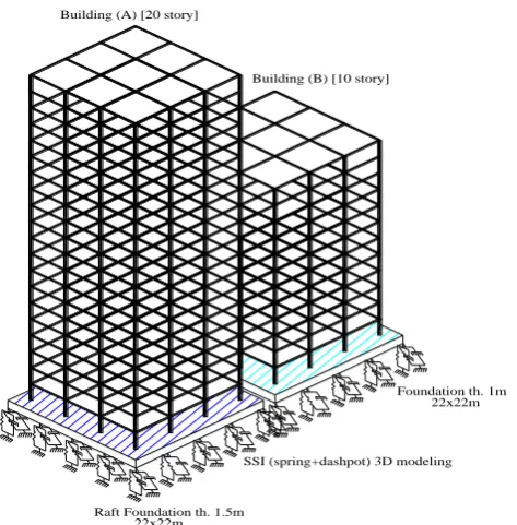
Two buildings are assumed to be symmetric buildings (Fig. 1) with their symmetric planes in alignment. Each building is modeled as a linear multi-degree of freedom system where the mass is concentrated at each floor and the stiffness is provided by the mass less walls or columns. This assumption indicates that earthquake excitation considered here is not severe or due to the significant increase of energy absorbing capacity the buildings are able to retain elastic and linear properties under the earthquake. The floors of each building are at the same level, but the number of story in each building was different. Each viscous damper device is modeled as a combination of a linear spring and a linear dashpot (Fig. 2). For the uncontrolled system the first three natural frequencies corresponding to first three modes of the building A are 3.3, 9.9, 16.8 rad/s and that of the Building B are 6.9, 20.8, 34.1 rad/s respectively. These frequencies clearly show that the modes of the buildings are well separated. A 3D model were constructed with foundation system (Fig. 3) to represent the real effect of soil type on connecting two adjacent buildings under earthquake excitations.
A B C E 1 2 3 5 1 2 3 5 A B C E 6.00 6.0 0 6.00 6.00 6.00 6.0 0 6.0 0 6.0 0
6 10/m'
6 10
/m
'
6 10/m'
6 10
/m
'
6 10/m'
6 10
/m
'
6 10/m'
6 10
/m
'
6 10/m'
6 10
/m
'
6 10/m'
6 10
/m
'
6 10/m'
6 10
/m
'
6 10/m'
6 10
/m
'
6 10/m'
6 10
/m ' 12 12 12 12 12 12 12 12 12 B 25x50 B 25x50 B 25x50 B 25x50 B 25x50 B 25x50 B 25x50 B 25x50 B 25x50 B 25x50 B 25x50 B 25x50 B 25x50 B 25x50 B 25x50 B 25x50 B 25x50 B 25x50 B 25x50 B 25x50 B 25x50 B 25x50 B 25x50 B 25x50 C55x55 C55x55 B 25x50 B 25x50 B 25x50 B 25x50 B 25x50 B 25x50 B
25x50 B 25x50 B 25x50 B 25x50 B 25x50
B 25x50 B 25x50 B 25x50 B 25x50 B 25x50 6 10/m'
6 10
/m
'
6 10/m'
6 10
/m
'
6 10/m'
6 10
/m
'
6 10/m'
6 10
/m
'
6 10/m'
6 10
/m
'
6 10/m'
6 10
/m
'
6 10/m'
6 10
/m ' 6.0 0 6.0 0 6.0 0 6.00 4 6.0 0 D D 6.00 4 6.00 6.00
K C K C K C K C K C K C K C Viscous Damper K C
Building (A) [20 storey] Building (B) [12 storey]
K C
Fig. 2: Plane of the two building Fig. 1: Typical plane structure of the two buildings
Building (A) [20 story]
Building (B) [10 story]
Foundation th. 1m
Raft Foundation th. 1.5m
SSI (spring+dashpot) 3D modeling
22x22m
22x22m
Fig. 3: 3D view of the two adjacent building with foundation system
Figure 4 shows five system of connecting the two adjacent buildings used in this study.
K
C
Building (A)
Building (B) K C
K
C
Building (A)
Building (B) K C
Building (A)
Building (B)
K
C
K
C
K
C
K
C
Building (A)
Building (B)
K
C K
C K
C K
C K
C
Building (A)
Building (B)
(i) One Damper (ii) Two Dampers (iii) Four Dampers (iv) Six Dampers (v) Twelve Dampers Fig. 4: Different placement of connected two buildings models with dampers
III.
VISCOUS DAMPER REPRESENTATION
The linear damper behaviour is given by:
E D K c
T
CV
KD
F
F
F
exp
(1),where FTis total output force provided by the damper, C is the damping coefficient, K is the spring constant, V
and Dk are the velocity across the damper and the displacement across the spring, respectively, c exp is the
damping exponent. The damping exponent must be positive. The practical range between c exp = 0.5 and 2.0 is
determined by [5] and [14]. In the numerical data of this study, c exp is taken as unity. It is evident that FT
consists of two parts. Damping force FD which equals C Vc exp. Restoring force FE According to [17], the
damping coefficient was determined to be around 1x10⁶ N. s m with a small variation for adjacent buildings in
their studies. Therefore, the damping coefficients in the five main examples are determined as cd= 0.25x10⁶ N. s
m and cd= 0.85x10⁶ N. s m respectively.
For all modes, both buildings have damping ratios of 5% of the critical structural damping (ζ=0.05). The structural damping coefficient in SAP 2000n is automatically calculated from the expression at below. Cdiag (2)
, where [C] is the modal damping matrix, M, and are the modal mass, the damping ratio and natural frequency, respectively. The mass and shear stiffness of each building are calculated. The same size of columns and beams has been used for the frames of two building models in order to investigate the sole control of fluid viscous dampers for different types of soils kinds.
connected at all floors and as the damping force is in proportion to the relative velocity of its both ends, the neighboring floors having maximum relative velocity should be chosen for optimal dampers locations.
IV.
MODELING OF SOIL – STRUCTURE INTERACTION
In Table 1, G is the small strain shear modulus of the soil, r represents the plate radius, and are the Poisson’s ratio and mass density of the soil, respectively. When a non-circular foundation is considered, an equivalent radius must be defined in order to use these equations. In the present study, the equivalent radius was obtained by equating the area of a circular plate to the square plate and solving for r. These constants were introduced to the spring-dashpot model developed in SAP2000[3]. These coefficient is represented the stiff, medium and soft soil.
Table 1: Values of Stiffness and damping coefficient of soil
Direction Stiffness (K) Damping (C) Mass
Vertical
1
4
Gr
379
.
1
K
r
1.5r3Horizontal
2 2
)
2
(
)
1
(
2
.
18
Gr
3
08
.
1
K
r
0.28r3r = plate radius; G =shear modulus; = Poisson’s ratio; =mass density
Source: Adapted from Fundamentals of Earthquake Engineering [8]
Figure 5 a FEM model has been purposely developed by subdividing the substructure (connected to superstructure) into a finite number of beam and shell element, connected to the surrounding ground by a series of frequency-dependent springs and dashpots in parallel representing the effects of ground deformability and energy dissipation.
Visco-elastic interface K y
Cy K x
Cx
K z Cz
interaction point in foundation level
Fig. 5: 3D Winkler Elements model SSI [1].
V.
INPUT LOADING
Total dead and live load on the area of the plane floor are 0.65t/m2 and weight volume of RC is 2.5t/m3.
Figure 3 Connected structures on different kinds of soil and considering the equilibrium of each mass, the equilibrium equation for each mass can be written as [11]
g
x
A
m
g
x
A
k
A
x
A
k
B
x
d
c
g
x
A
c
A
x
A
c
d
c
A
x
A
m
..
.
.
.
)
(
..
(3a)g
x
s
m
A
x
A
k
A
k
s
k
A
x
A
c
g
x
A
c
s
c
g
x
s
m
..
)
(
.
.
)
(
..
(3b)g
x
B
m
g
x
B
k
B
x
B
k
A
x
d
c
g
x
B
c
B
x
B
c
d
c
B
x
B
m
..
.
.
.
)
(
..
(3c)g
x
s
m
B
x
B
k
g
x
B
k
s
k
B
x
B
c
B
g
x
B
c
s
c
B
g
x
s
m
..
)
(
.
.
)
(
..
(3d)The governing equation of motion for the given system can be written in matrix form as
g
x
M
X
K
X
C
X
M
}
[
]{
}
[
]{
1
}
.
]{
[
}
..
]{
[
(4)where, x1and x2are the displacement responses, relative to the ground of structure 1 and 2 respectively, and
g
x
..
is the ground acceleration.
VI.
RESULTS AND DISCUSSIONS:
Two adjacent buildings with 20 (Building (A)) and 10 (Building (B)) stories are considered. The floor mass and inter-story stiffness are considered to be uniform for both buildings. The masses of the two buildings are assumed to be same and the damping ratio in each building is taken as 5%. The stiffness of each floor of the buildings is chosen such that to yield a fundamental time periods of 1.9 and 0.9 s for Buildings A and B, respectively. Thus, Building 1 may be considered as softer building and Building B as stiffer building. The adjacent buildings considered above are first connected with 1, 2, 4, 6, and 12 viscous dampers at the floor levels with fixed base cases(no) , then by using three types of soil (stiff, medium, and soft) represented by 3D Winkler model with raft foundation system, the two adjacent buildings were connected by the same way by viscous dampers. To get the optimum damper numbers and effect of different kinds of soil on connecting the two adjacent buildings, the displacements of each floor, top floor absolute accelerations and shear force of the each building is plotted with the damper number and changing of soil type as shown in Fig. 7, 8, 9 and 10 for the two earthquakes considered.
Figure 7 shows the response of the two adjacent building under El-Centrio earthquake excitation. Fig. 7-a represent a comparisons between the different cases of connecting with 1, 2, 4, 6, and 12 dampers with fixed base case (f), it is clear the reduction in the displacement of the two building using one damper by nearly 1.6 times than no damper case increasing the number of connecting dampers the reduction of displacement increase slightly for building A. For shear force using one or two (1 or 2) dampers reduce shear force by nearly 1.4 times less than no case, but use more than 2 dampers shear force increase by more than 1.2 times than no case especially for columns in the floor connected with dampers. Fig. 7-b shows displacement in different levels of building A on different kinds of soil connected with 1, 2, 4, 6, 12 dampers, and (No) case. From figure the top displacement constructed on stiff soil decreased by nearly 30% when use 1 damper than no case and when use 12 dampers top displacement decreased by 60% than no case. In medium soil, top displacement decreased by 1.32 and 1.6 times than No case using 1 and 12 connected dampers, and in soft soil top displacement decreased by 1.5 and 1.23 times than no case using 1 and 12 dampers respectively. Fig. 7-c represents shear force in different levels using 1, 2, 4,6,12 dampers and no case for building founded on different kinds of soil. In stiff soil shear force decreased by 1.17 times than no case using 1 or 2 dampers, whatever, shear force increase in columns at connected levels by nearly 1.4 times than no case, case of 12 dampers increase shear force of connected floor’s columns by nearly 1.5 times bigger than no case. In medium soil shear force decreased by 1.15 times than no case using 1 damper, but shear increased by 1.5 times than no case in the connected floor’s columns and when use 12 connected dampers shear force in columns increased by 2 times than no case. In soft soil shear force decreased by 1.2 times than no case using one damper but using 2 dampers increase base shear by 1.25 times than no case.
0 5 10 15 20
0 10 20 30 40
F
lo
or
No.
Dis(cm)
Nof 1f 2f 4f 6f 12f
0 5 10 15 20
5 10 15 20
F
lo
or
No.
Shear Force
Nof 1f 2f 4f 6f 12f
(1) Displacement (2) Shear force
(a) Response of building (A) connected with different numbers of link dampers with fixed base.
0 5 10 15 20
0 5 10 15 20 25 30 35
F
lo
or
No.
Dis(cm)
No
0 5 10 15 20
0 5 10 15 20 25 30 35
F
lo
or
No.
Dis(cm)
No
0 5 10 15 20
0 5 10 15 20 25 30 35
F
lo
or
No.
Dis(cm)
No
i) Stiff soil ii) Medium soil iii) soft soil (b) Displacement of Building (A) (20 storey) with link damper and different kinds soil.
0 5 10 15 20
5 10 15 20 25 30
F
lo
or
No.
Shear Force(t)
No
0 5 10 15 20
8 16 24 32
F
lo
or
No.
Shear Force (t)
No
0 5 10 15 20
10 15 20 25 30 35
F
lo
or
No.
Shear force(t)
No
i) Stiff soil ii) Medium soil iii) soft soil
(c) Shear Force of Building (A) (20 storey) with linked dampers and different kinds soil. Fig.7: El - Centro Earthquake response of buildings (A).
Figure 8 represents the response of building B under El Centro exaction. Fig. 8-a illustrated shear force in columns and floor displacements in different case of connected dampers. In fixed base case, shear force decreased by 2 times than no case when use 4 dampers and top displacement decreased by 2 times than no case. Generally connecting dampers in building (b) shows more uniformity in shear behavior of the building. Fig. 8-b shows displacements in different building’s levels in different kinds of soil founded. In stiff soil, top displacement decreased by 2.66 times using 2 dampers than no use case. Shear force decrease by 2 times using 2 dampers than no case. In medium soil displacement decreased using 2 dampers by 2.7 times than no case, soft soil shear force decreased by 2 times than no case, and base shear decreased using dampers by nearly 2.2 times than no case.
Top floor acceleration generally decreased when using dampers linked to building B by nearly 2 times than no case for all number of connected dampers.
0 2 4 6 8 10 12
0 5 10 15
F
lo
or
No.
Dis(cm)
Nof 1f 2f 4f 6f 12f
0 2 4 6 8 10 12
2 4 6 8 10 12 14 16
F
lo
or
No.
Shear Force(t)
Nof 1f 2f 4f 6f 12f
(1) Displacement (2) Shear force
(a) Response of building (B) connected with different numbers of link dampers with fixed base.
0 2 4 6 8 10 12
0 5 10 15 20 25
F
lo
or
No.
Dis(cm)
No
0 2 4 6 8 10 12
0 5 10 15 20 25 30
F
lo
or
No.
Dis(cm)
No
0 2 4 6 8 10 12
0 10 20 30
F
lo
or
No.
Dis(cm)
No
i) Stiff soil ii) Medium soil iii) soft soil (b) Displacement of Building (B) (12 storey) with link damper and different kinds soil.
0 2 4 6 8 10 12
5 10 15 20 25 30 35
F
lo
or
No.
Dis(cm)
No
0 2 4 6 8 10 12
5 10 15 20 25 30 35 40
F
lo
or
No.
Shear Force (t)
No
0 2 4 6 8 10 12
5 10 15 20 25 30 35 40
F
lo
or
No.
Shear Force (t)
No
i) Stiff soil ii) Medium soil iii) soft soil (c) Shear Force of Building (B) (12 storey) with linked dampers and different kinds soil.
Fig.8: El - Centro Earthquake response of buildings (B).
Figure 9 shows the response of the two adjacent building under Northridge earthquake excitation. Fig. 9-a represent a comparisons between the different cases of connecting with 1, 2, 4, 6, and 12 dampers with fixed base case (f), it is clear the reduction in the displacement of the two building using 1 and 2 dampers by nearly 1.7 times than no use case increasing the number of connecting dampers the reduction of displacement increase slightly for building A. Shear force using one or two (1 or 2) dampers reduced by nearly 1.7 times less than no case, but use 12 dampers shear force increase by more than 1.3 times than no case especially for columns in the floor connected with dampers. Fig. 9-b shows displacement in different levels of building A on different kinds of soil connected with 1, 2, 4, 6, and 12 dampers, and (No) case. From figure the top displacement of building A constructed on stiff soil decreased by nearly 1.6 when use 2 dampers than (No) case and when use 12 dampers top displacement decreased by 1.3 than No case. In medium soil top displacement decreased by 1.32 and 1.18 times than No case using 1 and 12 connected dampers, and in soft soil top displacement decreased by 1.4 times than no case using 1 and increased by 1.1 times using 12 dampers. Fig. 9-c represents shear force in different levels using 1 to 12 dampers and no case. In stiff soil shear force decreased by 1.77 times than no use case with using 1 or 2 dampers, whatever, shear force increase in columns at connected levels by nearly 1.3 times than no use case, case of 12 dampers increase shear force of connected floor’s columns by nearly 1.65 times bigger than no case. In medium soil shear force decreased by 1.05 times than no case use 1 damper, but shear increased by 2 times than no case in the connected floor’s column when use 12 connected dampers. In soft soil shear force equal to no case using 1 and 2 dampers but using 12 dampers increase base shear by 2.25 times than no case.
Top floor acceleration using 2 dampers equal to no case, but top floor acceleration decrease using 4, 6 and 12 dampers than no case.
0 5 10 15 20
0 10 20 30 40 50 60
F
lo
or
No.
Dis(cm)
No
0 5 10 15 20
4 8 12 16 20 24 28 32
F
lo
or
No.
Shear Force (t)
No
(1) Displacement (2) Shear force
(a) Response of buildings (A) connected with different numbers of link dampers with fixed base
0 5 10 15 20
0 8 16 24 32 40 48 56 64
F
lo
or
No.
Dis(cm)
No
0 5 10 15 20
0 31 62
F
lo
or
No.
Dis(cm)
No
0 5 10 15 20
5 10 15 20 25 30 35 40 45 50 55
F
lo
or
No.
Shear Force (t)
No
i) Stiff soil ii) Medium soil iii) soft soil
(b) Displacement of Building (A) (20 storey) with link damper and different kinds soil.
0 5 10 15 20
10 20 30 40
F
lo
or
No.
Shear Force (t)
No
0 5 10 15 20
10 14 18 22 26 30 34 38 42
F
lo
or
No.
Shear Force(t)
No
0 5 10 15 20
10 15 20 25 30 35 40 45
F
lo
or
No.
Shear Force (t)
No
i) Stiff soil ii) Medium soil iii) soft soil
(c) Shear Force of Building (A) (20 storey) with linked dampers and different kinds soil. Fig.9: Northridge Earthquake response of buildings (A).
Figure 10 represents the response of building B under Northridge exaction. Fig. 10-a illustrates shear force in columns and floor displacements in different case of connected dampers with fixed base, shear force decreased by 2 times than no case when use 1, 2, 4 dampers and top displacement decreased by 2 times than no case. Generally connecting dampers in building (B) shows more uniformity in shear behavior of the building. Fig. 10-b shows displacements and shear force in different building’s levels in different kinds of soil founded. In stiff soil, top displacement decreased by 2.33 times using 1 an 2 dampers than no use case, but using 12 dampers decreased displacement by 1.4 times than no case. Shear force decrease by 1.9 times using 1 and 2 dampers than no case, but using 12 dampers decreased shear force by 1.3times than no case. In medium soil displacement decreased using 1 damper by 1.7 times than no case, soft soil shear force decreased by 1.9 times than no case when using 2 dampers.
0 2 4 6 8 10 12
0 10 20 30
F
lo
or
No.
Dis (cm)
No
0 2 4 6 8 10 12
4 8 12 16 20 24 28
F
lo
or
No.
Shear Force (t)
No
(1) Displacement (2) Shear force
(a) Response of buildings (B) connected with different numbers of link dampers with fixed base
0 2 4 6 8 10 12
0 10 20 30 40
Ax
is
T
it
le
Axis Title
No
0 2 4 6 8 10 12
0 5 10 15 20 25 30 35 40
F
lo
or
No.
Dis(cm)
No
0 2 4 6 8 10 12
0 10 20 30 40 50
F
lo
or
No.
Dis(cm)
No
i) Stiff soil ii) Medium soil iii) soft soil b) Displacement of Building (B) (12) storey) with link damper and different kinds soil.
0 2 4 6 8 10 12
6 8 10 12 14 16 18 20 22 24 26
F
lo
or
No.
Shear Force (t)
No
0 2 4 6 8 10 12
10 15 20 25
F
lo
or
No.
Shear Force(t)
No
0 2 4 6 8 10 12
8 12 16 20 24 28
F
lo
or
No.
Shear Force(t)
No
i) Stiff soil ii) Medium soil iii) soft soil (b) Shear Force of Building (B) (12 storey) with link damper and different kinds soil.
Fig.10: Northridge Earthquake response of buildings (B).
It can be observed that the responses of both buildings are reduced up to a certain value of number of dampers, after which they are again increased. Therefore, it is clear from the figures that the optimum damper numbers exists to yield the lowest responses of both the buildings. The optimum damper numbers give the lowest sum of the responses of the two buildings. In arriving at the optimum numbers, the emphasis is given on the displacements, and shear force of the two buildings and at the same time care is taken those accelerations of the buildings, as far as possible, are not increased.
VII.
CONCLUSION
3D real two adjacent buildings subjected to two earthquakes connected in special arrangement in plane and vertical elevation connected with viscous dampers were investigated. The soil structure interaction represented by 3D Winkler model to give a real effect of three types of soil which the two buildings were founded on raft foundation system subjected to earthquake. Two fixed base adjacent buildings connected with viscous damper were taken as control case to other cases. From the above results the following conclusion can be drawn:
The viscous damper is quite effective in response control of the connected structures and higher reductions
in response can be achieved if the frequencies of the connected structures are well separated.
Displacements of tall building increase by nearly 1.2, 1.33 and 1.4 times when founded on stiff, medium and
soft soil respectively with respect to fixed base case, and shear force increased by 1.2, 1.4 and 1.6 when times founded on stiff, medium and soft soil respectively with respect to fixed base case.
Using two dampers (at top and first floor of the short building) decreased top displacement of tall and short connected buildings in noticeable values.
Connected points with campers increased shear force in columns by 1.20 times than not connected, so using
two dampers decreased shear force in columns and also base shear.
Buildings founded on stiff soil showed a similar response with fixed base especially in shear force.
Efficiency of connected buildings founded on soft soil decreased by nearly 25% than those founded on stiff
soil although the buildings which connected with two dampers (top and first floor) decreased its response by nearly 1.4 times than unconnected buildings.
As increasing numbers of connecting dampers, there is no significant decrease of response beyond certain
number, so it is not necessary to connect the two adjacent buildings by dampers at all floors but lesser dampers at appropriate locations can significantly reduce the earthquake response of the combined system. The responses of both buildings are reduced up to a certain value of the damping, after which they are again increased. Thus, the optimal numbers of dampers reduce the cost of dampers as well as the displacements.
Top floor acceleration generally, decreased with using dampers especially when use 2 dampers.
As a future work this system must be tested with different kinds of dampers to clarify the previous results and confirm the system.
REFERENCES
[1] Ahmed Abdelraheem Farghaly and Hamdy Hessain Ahmed, (2013) “Contribution of Soil-Structure
Interaction to Seismic Response of Buildings”, KSCE Journal of Civil Engineering 17(5):959-971.
[2] Bharti S., Dumne S., and Shrimali M. (2010) “Seismic response analysis of adjacent buildings connected
with MR dampers”. Engineering Structures, 32(8), 2122:2133.
[3] Computers and Structures, I. (2007) SAP2000: Integrated finite element analysis and design of structures, Berkeley, CA.
[4] Hadi, M. N. S. and Uz, M. E. (2009) “Improving the dynamic behaviour of adjacent buildings by connecting them with fluid viscous dampers”, 2nd International Conference on Computational Methods in Structural Dynamics and Earthquake Engineering, Island of Rhodes, Greece, 280.
[5] Hou, C. Y. (2008) “Fluid dynamics and behaviour of nonlinear viscous fluid dampers”, Journal of Structural Engineering, 134(1), 56-63.
[6] Hwang, J.S., Wang, S.J., Huang, Y.N., and Chen, J.F., (2007). “A seismic retrofit method by connecting viscous dampers for microelectronics factories”. Earthquake Engineering and Structural Dynamics, 36(11):1461-1480. [doi:10.1002/eqe.689]
[7] Kasai K, Maison BF. Dynamics of pounding when two buildings collide.(1992),”Journal of Earthquake Engineering and Structure Dynamic ;21:771–86.
[8] Newmark, N. M. and Rosenblueth, E. (1971). “Fundamentals of earthquake engineering.” Prentice Hall, Englewood Cliffs, NJ, pp. 93-100.
[9] Patel, C. C. (2011)” Dynamic Response of Similar Structures Connected By Viscous Damper” International Journal of Earth Sciences and Engineering ,ISSN 0974-5904, Volume 04, No 06 SPL, pp. 903-906.
[10] Patel, C.C. and Jangid, R.S. (2010), “Seismic Response of Adjacent Structures Connected with Maxwell
Dampers”, Asian Journal of Civil Engineering (Building and Housing) Vol. 11, No. 5 Pages 585-603
[11]
Patel, Chirag C, Jangid, R S, (2008) "Influence of Soil-structure Interaction on Response of
Adjacent SDOF Structures Connected by Viscous Damper", The 12th International Conference
of International Association for Computer Methods and Advances in Geomechanics
(IACMAG),1-6 October, Goa, India.
[12] Qi, X. X. and Chang, K. L. (1995) “Study of application of viscous dampers in seismic joints”,
proceeding of the International Conference on Structural Dynamics, Vibration, Noise and Control, Hong Kong.
[13] Tesfamariam S.and Saatcioglu M.(2010) ” Seismic vulnerability assessment of reinforced concrete
buildings using hierarchical fuzzy rule base modeling”. Earthquake Spectra, 26(1), 235:256.
[14] Tezcan, S. S. and Uluca, O. (2003) Reduction of earthquake response of plane frame buildings by
viscoelastic dampers, Engineering Structures, 25(14), 1755- 1761.
[15] Uz, Mehmet Eren,(2009) “Improving the dynamic behaviour of adjacent buildings by connecting them
with fluid viscous dampers”, Master of Engineering - Research thesis, School of Civil, Mining and
Environmental Engineering, University of Wollongong. http://ro.uow.edu.au/theses/3429.
[16] Warnotte, V., D. Stoica, and S. Majewski.(2007),” State of the Art in the Pounding Mitigation
Techniques”.Structural Mechanics, 4 no. 3:102-117.
[17] Xu, Y. L., He, Q. and Ko, J. M. (1999) Dynamic response of damper-connected adjacent buildings under
![Fig. 5: 3D Winkler Elements model SSI [1].](https://thumb-us.123doks.com/thumbv2/123dok_us/8355272.1668580/4.595.204.387.402.553/fig-d-winkler-elements-model-ssi.webp)
![Figure 3 Connected structures on different kinds of soil and considering the equilibrium of each mass, the equilibrium equation for each mass can be written as [11]](https://thumb-us.123doks.com/thumbv2/123dok_us/8355272.1668580/5.595.71.510.112.277/figure-connected-structures-different-considering-equilibrium-equilibrium-equation.webp)


