R E S E A R C H
Open Access
Surface editing using swept surface 3D
models
Xiaohui Wang and Jingyan Qin
*Abstract
This paper presents a system for editing strip-like patches on the mesh using swept surface. The user first selects a rough cylinder-like region, the boundary of which is automatically refined. A swept surface approximation is automatically done, including extraction of the trajectory and the corresponding deforming 2D curves. The swept surface is described by a map from a real interval to both rigid body deformations and 2D curves. These 2D curves are analyzed and decomposed into many elements, which can be edited respectively, and a novel pattern analysis is also performed on these elements to extract curve patterns. These 2D curves serve as handles for controlling the geometry, and modifications to them can change the geometry directly. Thus, users can just edit the pattern or element curve to control the global geometry. We show the novelty and efficiency of our framework using varietal demonstrations.
Keywords:Swept surface, Feature editing, Pattern analysis
1 Introduction
To meet the growing needs for 3D models, modeling from existing models is becoming a practical way for generating new models rapidly and efficiently. Local sur-face editing is a popular way for this, which is also an important and active research topic in computer graphics.
The state-of-the-art local surface editing techniques depend on intrinsic coordinates, such as multi-resolution decompositions [1] and various shape de-formation frameworks. Both provide efficient and reli-able functionalities for deformation, geometry transferring, and so on. However, such techniques focus on global deformation of the surface patch or geometry transferring, which is not competent for more sophisti-cated surface editing with rich user interaction.
Though professional modeling packages [2, 3] can pro-vide precise control using parametric patches or subdiv-ision surfaces, they are really sophisticated and tiresome to use, especially for inexperienced users. In users’point of view, surface editing or modeling by 2D curves is al-ways the ideal choice. The most famous example is teddy [4], which is a huge success and is significantly im-proved by a recent work [5].
In the meanwhile, pattern recognition techniques de-velop rapidly in recent years. In the graphics field, tech-niques such as geometry feature (or pattern) clustering and analysis play a more and more important role. Typ-ical work is [6], in which local featured areas are clus-tered and matched using geometrical descriptors. In a more recent work [7], they present a framework for dis-covering structural regularity including similar transfor-mations. However, geometric features are hard to analyze. Current approaches focus on similar transfor-mations extraction or local geometrical descriptor ana-lysis. Both rely on simple geometric properties such as curvature. The applications are limited to simple geo-metric patterns with similar curvature distributions. More complicated patterns sensitive to human beings cannot be analyzed. Using such analysis for easier sur-face editing is even harder. To the best of our know-ledge, no existing technique exploits pattern recognition for better user experience. Just think of the following scenario: you select a part and edit it, all similar parts changed, and then, the editing work is significantly simplified.
As discussed above, our goal is to design a local sur-face editing approach for free and convenient design, es-pecially for inexperienced users. We particularly desire the following properties for the approach:
* Correspondence:[email protected]
School of Mechanical Engineering, University of Science and Technology Beijing, Beijing, China
Usability: It must be sufficiently easy to use. 2D curve editing instead of sophisticated parameter control is always preferred.
Intelligence: It must be smart enough to handle boring repetitive work automatically, such as applying similar modification to similar parts can be done by just selecting one part, editing it, and all done.
Functionality: It must be powerful enough for complicated surface editing.
However, it is a challenging job. Precise control and easier user interaction is somewhat a contradiction. And intelligent interaction such as handling repetitive work automatically is even harder.
Luckily, we observe that a significant amount of fea-ture regions we can see in 3D models are cylinder-like and have the nature of sweeping, that is, they can be de-scribed by swept surface. In general, it is known as swept volume, which is generated by the motion (including de-formation) of arbitrary 3D object. In this paper, we only consider swept surface generated by restricting the ob-ject to be planar curves. The swept surface is a natural, intuitive, and convenient 3D modeling method with a long history and is widely used in computer-aided design (CAD) field. It is generated by moving curveC1(v) along another curve C2(u), which are called profile curve and trajectory curve respectively, andC1(u) may be deformed during its motion along the trajectory. Swept surface can naturally decompose the shape into the trajectory and associated profile curves. If we restrictC1(v) to be planar curves, it can be described and analyzed easily using cross-planes given by local Frenet frames [8] of the tra-jectory. Then, editing the surface details becomes editing 2D curves, which provides both convenient and precise controlling of the shape. The most exciting thing is that the analysis of the geometry similarity becomes the ana-lysis of a sequence of 2D curves, which is much easier. Such analysis also enables the system to supply intelli-gent editing as mentioned above. These 2D profile curves can be further decomposed into many elementary elements, including PCA (principle component analysis) and multi-resolution analysis, each of which can be ana-lyzed and edited independently. This is also our main motivation. In CAD field, this is also known as general-ized cylinders [9]. Modeling using generalgeneral-ized cylinders is done through construction of the trajectory and the profile curves (cross-section curves), respectively.
Our work is also closely related to skeleton extraction methods as it is a crucial step for extracting the trajec-tory of swept surface. And a severe problem is that it is hard to extract the skeleton for open mesh, as common automatic methods such as medial-axes-based are ill-posed. In [10], they present a novel method for the
extraction of mesh skeleton, which is robust and can bring a direct relation between the mesh vertices and the skeleton. We further improve this method to enable it to work on open mesh.
The major contributions of this work are:
A swept surface representation of local surface patch. It provides the fundamental technique of the whole system. It allows users to edit local surface freely and efficiently and enables better pattern analysis for intelligent editing.
Approximating mesh surface patch by swept surface. We present a robust way of approximating surface patch by swept surface.
Analysis of patterns using swept surface. We present a novel way for detecting repetitive patterns along the trajectory.
A special fine property is that all the operations, including varieties of editing and even geometry transfer, do not need a reparameterization, that is, we can keep the topology of mesh while doing such editing work.
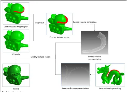
The pipeline of the system is illustrated in Fig. 1. The user first selects a rough region, which is automatically refined. Then, a swept surface representation of this re-gion is built, including decomposition into lower level elements and analysis for repetitive patterns. Then, the user can edit the 3D model by editing 2D curves. She/he can just edit one of the patterns, and all the other similar shapes will change automatically.
The left of the paper is arranged as the following. Sec-tion 2 is a descripSec-tion of our swept surface representa-tion of mesh patch. Section 3 is an informal introduction of the user editing procedure of the system, that is, how the user can use our system to edit the mesh patch. Section 4 is the creation algorithm part and explains how the swept surface representation is created. Section 5 is the decomposition step for decomposing 2D curves to lower level elements, which can be edited re-spectively. Section 6 explains our analysis algorithm for further facilitating the user editing. Section 7 explains when the user finishes editing of the 2D curves and how the original mesh is modified.
2 The swept surface representation
2.1 Swept surface
Roughly speaking, the swept surface representation in-cludes the trajectory curve and the profile curves. We denote profile curves as C1: [0,1]×[0,1]→R2. For each u∈[0,1],χ(v) =C1(u,v) denotes a planar curve. The sur-face function can then be written as
where ξ: [0,1]→R3 denotes the trajectory and τ∈M3×2
rotates the planar curve.ξ together withτmap the
pla-nar curves into 3D space. We denote the local Frenet
frame by (T(u), N(u), and B(u)), where T(u), N(u), and
B(u) are tangent, normal, and binormal unit vectors,
re-spectively, at the trajectory point ξ(u). Then, generally,
τ(u) maps unit vectors along X- and Y-axis toN(u) and
B(u), respectively, and can be written as τ(u) = [N(u),
B(u)]∈M3×2. We also call the plane given by point ξ(u)
and normalT(u) the cross-section plane.
2.2 Discrete swept surface patch on mesh
To clarify the subsequent statements, we suppose that the mesh hasnvertices. We useV= {1, 2…n} to denote the set of its vertices.E= {(i,j)} is the set of edges, andVEis the set of all the points on edges (including vertices). We identify (i, j) and (j,i) for each edge. For each pointi,N1(i) means the one-ring points ofi. We useviandnito denote the original position and normal for vertexi, and vi’is the new position. Vertices of the selected region are denoted byVS.
As we focus on using the swept surface to represent a surface patch on a triangular mesh to be edited, the fol-lowing properties of such representation is required:
Discreteness. As the patch is to be analyzed and edited, a discrete representation is needed. Editing. Editing of swept surface can change the
mesh patch while keeping other regions of the mesh.
As discussed above, to approximate the continuous case, the transformation can be represented as:
ξi; τi;i¼1;2;…;n ð2Þ
where n is the number of sample points on the
trajec-tory. Parameterize the trajectory by length, then the
length for each point is denoted byli,i= 1, 2,…,n.
The corresponding profile curve is denoted as quaternions
Xi¼ ci;jjj¼1;2;…mi
; i¼1;2;…;n ð3Þ
wheremiis the number of sample points on each curve.
Each ci, j is a quaternion corresponding to a point
de-noted as (p,k,l,λ), where p∈R2is the 2D position of the
point in the local frame and (k, l) ∈E andλvk + (1-λ)vl
gives the 3D position of the point. We keep this
information to modify the original mesh when complet-ing editcomplet-ing the 2D curves.
Forℂi,j= (p,k,l,λ), we use ℂip,j,ℂik,j,ℂil,j,ℂi,jλto repre-sentp,k,l,λ, respectively, and useℂip,jto denote the pro-jected 3D positionτiℂip,j+ξi.
3 User editing
We provide a novel user editing scheme. The main pic-ture of editing is as follows: The user selects a rough strip region of interest (ROI), which is automatically re-fined to a better region smooth. Here, better mainly means the region should be dissimilar to its nearby re-gions; see top of Fig. 1 for example. Then, our system automatically represents the region using a swept sur-face. For the user, it is just a sequence of profile figures. The editing work then becomes editing a sequence of planar curves. Essentially speaking, the editing work is to replace each curve of the sequence by another curve. Of course, the user does not have to edit each curve he wants to modify as it is really a boring work. To simplify the editing work, we design a scheme of editing based on hierarchical curve decomposition and repetitive pat-tern analysis. Intuitively, each curve is decomposed into several sub-elements, each of which is either a real value or another curve and can be edited respectively, while the modified elements can then assemble back to the whole curve. Note that each sub-curve can still be subdi-vided into other low-level elements, which can also be edited to change its parent curve. With such decompos-ition, editing such sequence of planar curves then be-comes the editing of the sequence of lower level elements, though the sequence of lower level elements
may still be a sequence of simpler planar curves, which is more convenient for editing. The repetitive pattern analysis further simplifies the editing step. Here, repeti-tive means repetirepeti-tive sub-sequence up to a scale of the interval length. A detailed description of the decompos-ition and analysis is given in Sections 5 and 6; here, we just enumerate several common scenarios of the editing work.
Modify a sub-sequence of curves when the user just wants to change a small portion of the curve se-quence. Usually, he does not have to change each of the curves. For example, he may make an affine transformation for one figure and use the same transformation for each of the curves. He may apply specify several transformations for some of them, and the system applies interpolated transformations for other curves automatically. He may also create new curves using similar methods to replace all them.
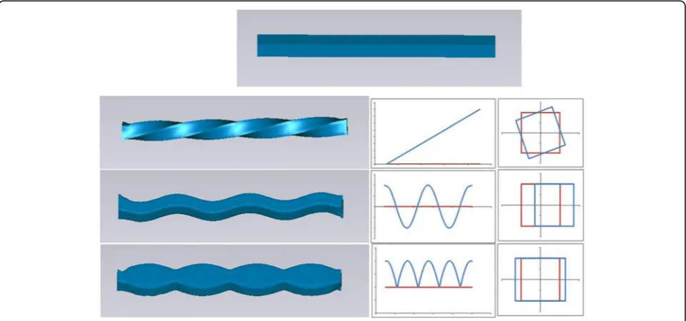
Editing the sequence using a single curve. When the curve decomposition includes real values, these values can then be edited as a single real-valued function (see Fig.2for example). The profile figure of the cuboid is a sequence of squares. Using PCA analysis, the rotation angle for one of the principle directions is a constant or a straight line of that de-scribed by a real value function. We just replace the line by another straight line, and then, the cuboid becomes twisty.
Editing repetitive templates. When the curves have the character of repetition, our system can further
facilitate the editing work by an automatic analysis of such patterns. The user may just select a single pattern and replace it, and then, all the occurrences of the pattern are changed (see Fig.5).
Using template library. We also design a template library for replacing existing curves by other pre-designed curves. The user may replace portions of the curve sequence or patterns by pre-designed curves.
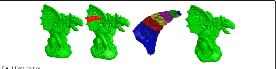
Geometry transfer. Though it is not our main purpose, our system can still easily handle cylinder-like feature transfer. Each of the elements can be transferred respectively. This is done by replacing the sequence of target model by the corresponding element function of the source model (see Fig.3).
4 Methods—creation of swept surface
Creation of the swept surface representation is the fun-damental step of the pipeline. There are three steps:
Refinement of selection. The shape of the swept surface region is crucial to subsequent analysis and editing. However, it is impossible for users to select a precise region as they need. Generally, the most important quality of the boundary is the
smoothness, which means the smoothness of not only the curve itself but also the region it crosses, that is, it should not cross the boundary of dissimilar regions. To ensure this criterion, we require the smoothness of both the curve and the normal of the original mesh along the curve. Extraction of trajectory. The trajectory extraction is
the pivotal step for creation of the representation. To create a meaningful swept surface, traditional skeleton is always the ideal choice. However, as the selected region is a cylinder-like open mesh, with surface details or noise, it is a challenge to extract the skeleton from such open mesh, and traditional methods such as Reeb graph, potential field, distance field, or medial surface will not give a robust and re-liable solution. So, we use a variety of the method in [10]. However, there are sometimes more than one
connected curves for each plane, and only the main curve is preserved.
Refinement of trajectory and extraction of profile curves. The profile curves are extracted by the intersection of the cross-section planes and the mesh.
4.1 Refinement of selection
We use a graph-cut-based approach to refine the selec-tion. Given a mesh patch of triangles, our goal is to get a refined patch with the above properties. The mesh is converted to a weighted undirected graph by taking every face of the mesh as a graph vertex, every edge shared by two faces as a graph edge, and the graph is represented asG= (V,E). Denote the initial selected re-gion as Vinit. Before defining the edge weights, we first define the distance between neighboring triangles. Be-sides geometry distance, the distance definition must re-flect the variability of normals, as it is the key factor for distinguishing mesh regions and is commonly used in mesh segmentation methods. To integrate the above considerations, we define the distance for neighboring triangles as follows:
distance¼
ffiffiffiffiffiffiffiffiffiffiffiffiffiffiffiffiffiffiffiffiffiffiffiffiffiffiffiffiffiffiffiffiffiffiffiffiffiffiffiffiffiffiffiffiffiffi
ω1d2geometryþω2d2normal q
ð4Þ
where dgeometry and dnormal denote the distance for
geometry and normal, respectively, and ω1 and ω2
are the two importance factors for the two distances.
The geometry distance dgeometry is defined as follows:
bend the two triangles along their common edge to
let them on the same plane, and dgeometry is defined
as their barycenter distance on the plane. And their
normal distance is defined as dnormal = |n1 − n2|,
where n1 and n2 are the normals of the two
trian-gles. And the edge weight for the two neighboring
faces is defined as w = e−distance. The next is to
de-fine the initial set of selected region Vselect and
unse-lected region Vunselectas follows:
Vselect¼ (
v∈Vinitjvhas a certain distance
from the boundary ofVinit
)
ð5Þ
Vunselect¼ (
v∈V−Vinitjvhas a certain distance
from the boundary of Vinit
)
ð6Þ
Suppose the final selected and unselected vertices are V0select and V0unselect. We want to optimize the following energy function:
E¼Eedge þ Evertices ð7Þ
where
Eedge¼
1 2
X
u;v
ð Þ∈E;u∈V0
select;v∈V 0 unselect
ωðu;vÞ ð8Þ
Evertices ¼ωselect v∈Vjv∈Vselect;v∉V 0 select
n o
þ ð9Þ
ωunselect v∈Vjv∈Vselect;v∉V 0 unselect
n o
This is essentially a graph-cut problem. To solve it, we first build a directed graph by creating two directed edges with the same weight for each edge ofGand cre-ate a source vertex connecting to the vertices in Vselect with weightωselectand a sink vertex connected from the vertices in Vunselect with weight ωunselect. Then maximal flow algorithm is used to solve it.
We apply the following rule to further smooth the boundary. For each vertex on the boundary, the span-ning angle formed by it and its two neighbors is com-puted. At each time, the vertex that has the smallest value of angle and of which two neighbors share an edge on the original mesh is removed by connecting its two neighbors directly on the boundary. The process is re-peated iteratively.
4.2 Extraction of skeleton
The method in [10] contains two steps: geometric con-traction and connectivity surgery. We extend the first step to mesh with boundary and retain the latter unchanged.
The following statements take the mesh patch as a separated mesh. We denoteEand E as its interior edges set and boundary edges set, respectively.
In [10], they solve the following sparse system for mesh contraction:
∥WLLV 0
∥2þX i
W2H;i∥vi0−vi∥2 ð10Þ
whereLis then×ncurvature flow Laplace operator:
Lij¼
ωij¼ cotαijþ cotβijifð Þi;j∈E
ωij¼2 cotαPij ifð Þi;j∈E
i;k ð Þ∈E
k
−ωik
ifi¼j
0 otherwise 8 > > > > > > > > > < > > > > > > > > > :
ð11Þ
For a given pointi, the Laplacian constraint can be re-written as
X
k∈N1ð Þi
ωikðvk−viÞ ¼0 ð12Þ
However, this does not work for boundary points. We observe that if the patch is mirrored along its boundary, then the boundary points become inner points. We do not need to really mirror the patch, such as creating new points. Instead, we use a modified version of the Lapla-cian contraction, and these boundary points contract normally along the inward curvature flow in normal di-rections as inner points.
Suppose thatiis a boundary point and its two bound-ary edges aree1 ande2; the normal of the planePi deter-mined by e1 and e2 isn = e1e2
∣∣e1e2∣∣. For another point j∈N1(i), it mirrors by planePiwhich is given by a linear mirror operatorσi, which has the form
σið Þ ¼x Aixþbi ð13Þ
where
Ai¼I−2nnT;bi¼ð2vi⋅nÞn ð14Þ
Then, the equation can be rewritten as
X
i;k
ð Þ∈E
ωikððvk−viÞ þðσð Þvk −viÞÞ þ X
i;k
ð Þ∈E
ωikðvk−viÞ
¼0 ð15Þ
This leads to a new curvature flow matrix L’, and the constraint function becomes:
∥WLL 0
V0∥2þX
i
W2H;i∥vi0−vi∥2 ð16Þ
trajectory, we denote the vertices associated with the tra-jectory byVs0and useTto denote the trajectory.
4.3 Refinement of trajectory and profile curves
Our goal is to create the swept surface representation, composed of the trajectory and profile curves, as in Sec-tion 2.2. We use an iterative step to refine the trajectory and profile curves. In each step, we first use current configuration of S(vi) and Vs1 to find the profile curves and refine the trajectory and then use the new trajectory to renewS(v) andVs1.
Profile curve extraction. The local Frenet frame at each vertex of the trajectory is calculated using discrete geometry, including the associated cross-section planes.
For each trajectory vertext, its associated profile curve is obtained through the intersection of its cross-section plane and triangles of the mesh. We suppose each inter-sectant triangle intersects the plane with its two edges. Then, for each cross-section plane, its cross-section curves are 1-manifold which may have boundary points. However, there may be more than one connected com-ponent. The reason for this is that some curves which do not belong to the trajectory vertex are also crossed by the plane. To resolve this, we measure the projection of each component to the trajectory. For each compo-nent, letVbe its vertex set, and we define:
MeanDistance Vð Þ ¼Pv∈Vd S vð ð Þ;tÞ
V ð17Þ
Here, MeanDistance measures the mean belonging likelihood, the less value the MeanDistance has, the more likelihood this component belong to the vertex t. So, we just choose the component has the minimal value
ofMeanDistance.
For each point on edges, the associated Frenet frame plane can still be calculated by a linear interpolation of its two endpoints. And the extraction of the profile curves can be processed in a similar way. To this end, S(v) andVs1can be updated. For each point t∈T, we de-note γ(t) the associated cross-section curve. Denote the new function isS′(v), then
S0ð Þ ¼v argminv∈γð Þtðd tð;S vð ÞÞÞ ð18Þ
Note that if there is no pointtsuch thatv∈γ(t), then we denote S'(v) =ϕindicating thatvis not controlled by the swept surface. And updated set ofVs1is defined as=
Vs1= {v|S'(v)≠ϕ}.
Trajectory refinement. The trajectory is refined with respect to both the smoothness and the embedding.
Suppose current positions of the trajectory vertices arex1,x2,…,xn, then the new positionsx1’,x2’,…,xn’
is given by minimizing the quadratic:
F¼ω1F1þω2F2 ð19Þ
whereF1is a discretized tension spline energy similar to
[11], which is given by
F1ðxi1; ;xi2;…; ;xinÞ ¼ X
k
∥2xik−xik−1−xikþ1∥ 2
þλ∥xikþ1−xik∥
2 2
6 6 6 6
4 ð20Þ
AndF2is the embedding term, given by
F2
¼Xi
∥x0i−Average Wγð Þxi
∥2 h
ð21Þ
where Average(⋅) denotes the mean position of a set of
points. We further divide V into two subsets:
con-strained pointsV1and free pointsV2. Constrained points
V1 is defined by the vertices in final set VS0, which is
controlled by the swept surface, and free points
V2=V−V1should not be controlled. Note thatV1∈VS,
but we do not guarantee that every point inVSis a
con-straint by the swept surface.
5 Decomposition of planar curves
To make the editing of sequence of planar curves prac-tical, each planar curve can be decomposed into several independent lower level elements. The main motivation of such decomposition is to create an easier human-computer interaction, and another motivation is to fa-cilitate pattern analysis. Formally, for any curveC, there are several elements C1, C2,…, Cn, such that C = F(C1, C2,…,Cn), where F is the inverse map from lower level elements to the whole curve. EachCi may be real value or planar curve.
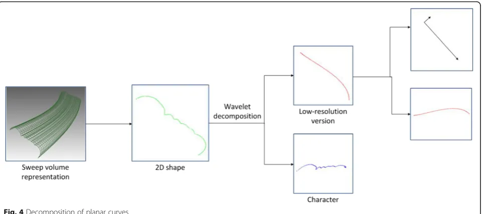
We propose two decomposition schemes. One is based on affine transform, and another is based on multi-resolution curve analysis. Figure 4 is an example.
Affine decomposition. Affine transform is a map of the form
F Að ;b;xÞ ¼Axþb ð22Þ
where A is a non-singular 2×2 matrix and b∈R2is the
translate component. An affine decomposition is to
rep-resent the curveCas A, b,C′such thatF(C′) =C, that
get curve C. Since A, b is collection of real values, the low-level elements are essentially a set of real values and another curve. The user can then just edit
A, b, or C′, and then, C is changed by the map F.
The user can, for example, edit a sequence of one of
the real components of A by just editing a single
curve.
Specially, we can restrictAto be a rigid body, similar transform, that is, A is controlled by less than four real values. A special case is PCA analysis, where b is the barycenter ofC, andA is composed of its two main di-rections. Figure 2 is a special case of such editing.
Multi-dimensional decomposition. A curve can be further decomposed into multi-level curves using the B-spline wavelets. It has the form C= F(C1,
C2), where F is the wavelet reconstruction
oper-ator and C1 and C2 are the base curve and
de-tailed curve, respectively. Each curve may be edited respectively. This decomposition can be used to handle planar geometry textures as in Fig. 3.
6 Analysis of sequence
Analysis is the key step to provide the intelligence in the system and can magically ease the editing work.
6.1 Analysis representation
The repetitive pattern analysis is performed on a se-quence of elements.
For a clearer description, we start from the continuous case:
There is a function f:[a, b]→D, whereD is the object space, depending on the decomposed element. Dcan be R, the space of real numbers, or the space of planar curves. It can also be customized to other spaces. The task is to find some templates, which is also a function defined on [a, b]. Doing some transformations (depend-ing on D, e.g., translation and scaling) using these tem-plates can give f, or say, decompose [a, b] to some disjoint segments, which can be clustered into several groups, each of which can be generated using a specific template. There are several criterions for a good decomposition:
Fig. 4Decomposition of planar curves
The templates should be neither too long nor too short.
There should be as less templates as possible. There should be as less segments of [a,b] as
possible.
The discrete case is almost the same. Letabe 0 andb length of the trajectory. For each sample pointi, we just let f(li) the specified associated element, where li is the length parameter for the point as in Section 2.2. Other values of f are assigned using linear interpolation. We call the functionfthe element function.
6.2 Extraction of template
After the extraction of trajectory and profile curves, we aim to find the templates of the element function f along the trajectory. Here, we present a novel pat-tern analysis process. The algorithm is described as follows:
In order to find templates, sets of similar segments along the trajectory are computed at first. A segmentsi is denoted as [si0,si1], wheresi0and si1are the start and end of sample points along the trajectory. Two segments are considered similar if their distance is less than a pre-scribed threshold. The distance metric of segments can be defined based on the property of functionf.
After that, for the sake of the criterions described in Section 6.1, for each set of similar segments Si = {sn1, sn2,…, sni}, the maximum coverage of non-overlapping segments of that set is computed, which is defined as follows:
max X
sk∈SB
jjsk1−sk0j jSB⊆Si;∀sm;sn∈SB;sm∩sn¼ϕ
8 < :
9 =
; ð23Þ
The set Si that has the maximum value of maximum coverage is then found out, and the corresponding set of non-overlapping segments is reported. The next possible template is extracted by repeating the above process after eliminating the reported segments from the trajectory.
In the case of handling planar curves, we use the cen-troid distance-based Fourier descriptor [12] as the shape descriptor of planar curves to compute the distance metric of segments, because it is suitable for describing planar curves. Each planar curve is then represented by a feature vector:
F cð Þ ¼i ða0; ;a1;…; ;ad−1Þ ð24Þ
where ak(k = 0,1,…, d − 1) is the coefficient of Fourier
descriptor of curve ci. The difference of two curves is
measured by theL2distance of the feature vectors. The
distance of two segments is defined as the sum of dis-tance of corresponding planar curves. To find similar
segments, a k-means clustering algorithm is performed
in that d-dimensional feature space to group planar
curves intoK clusters, named {C1,C2, …,CK}. Then, for
each two curve ci and cj in the same cluster Ck, a
segment-growing algorithm is performed by extending each segment along the trajectory until their distance
reaches a prescribed threshold. The segment si that
ap-pears most frequently in a cluster after the growing
process is extracted as the representative segment of
cluster Ck. For each representative segment s extracted
as above, a set of similar segments Si is obtained by
searching along the trajectory.
In other cases, the distance metric of segments can be defined based on property of functionf. For example, if the object spaceDis R, the distance is defined as theLn distance of two real functions.
7 Modification of the mesh
After profile curves being modified, the original mesh should be changed due to changed 2D curves. As men-tioned in Section 2.2, regions controlled by the swept sur-face should be modified corresponding to the swept surface, while other regions should retain their original shapes. To keep the topology of the mesh, we only modify the positions of vertices. So points in V1should be con-strained by the swept surface, and points inV2should be constrained by their original local coordinate, which is, in our implementation, the Laplacian coordinate.
For simplicity, the Laplacian operator is defined with uniform weights
ϑð Þ ¼vi vi−
1
N1ð Þi X
j∈N1ð Þi
vj ð25Þ
The new positions of vertices are then obtained by minimizing the following quadratic energy:
Etotal ¼ω1Esweptþω2Eaverageþω3Elapacian ð26Þ
Eswept¼ X
i;j
∣ℂλ
i;jvkℂi;j
0þ 1−ℂλ
i;j
vlℂi;j0−ℂPi;j
2
ð27Þ
Eaverage¼ X
i∈V1
∣ ϑ v0i 2 ð28Þ
Elapacian¼ X
i∈V2
∣ ϑ v0i −ϑð Þvi 2
ð29Þ
The swept term controls the shape to be consistent with the swept surface. And the Laplacian term in Equa-tion 29 constraints uncontrolled vertices to their original shape. However, the above two terms cannot determine a smooth shape (and sometimes there are infinitely many solutions). So, we use an average term to further control the smoothness of the controlled region.
8 Results and discussion
We have implemented our system and successfully tested it on a variety of models. Figure 5 shows an illus-tration for feature editing. The left image is the original model, and the middle one is the edited model with the template of the dragon’s backbone. Figure 6 shows a funny example of geometry transferring for jokes. In this example, the geometric texture of dragon’s backbone is transferred to the model of a mouse tail. Figure 7 dem-onstrates detail enhancement for models. The region marked in red enhances the geometric texture in detail.
9 Conclusions
In this paper, we proposed a novel framework for mesh editing using swept surface. The user just selects a cylinder-like patch and then can edit it as 2D figures. A swept surface approximation is automatically done, in-cluding extraction of the trajectory and the correspond-ing deformcorrespond-ing 2D curves. A novel pattern analysis is done, so the user can change a set of elements by just editing one of them. Demonstrations show the novelty and efficiency of this framework.
The swept surface analysis can be extended to multi-trajectories, that is, the trajectory is not restricted to a single line. As for the future work, we intend to imple-ment a multi-grid linear solver, which can significantly improve the algorithm performance.
Acknowledgements
The authors thank the editor and reviewers.
Funding
This work was supported by the Natural Science Foundation of China (61602033), the Social Science Fund of Beijing (16YTC027), the Science and Technology Plan Project of Beijing (Z171100001217009), and the
Fundamental Research Funds for the Central Universities (FRF-TP-15-027A1).
Availability of data and materials We can provide the data.
Authors’contributions
XW did the main work of the work. JQ did the experiments.
Ethics approval and consent to participate We approved.
Authors’information
Xiaohui Wang, female, has a PhD degree, and is from the School of Mechanical Engineering, University of Science and Technology Beijing. Her main research interests are computer vision, pattern recognition, affective computing, and interdisciplinary research across computer science and art design. Jingyan Qin, female, is a professor, has a PhD degree, and is from the School of Mechanical Engineering, University of Science and Technology Beijing. Her main research interests are interaction design, information design, and information visualization on big data.
Consent for publication We agree.
Competing interests
The authors declare that they have no competing interests.
Publisher’s Note
Springer Nature remains neutral with regard to jurisdictional claims in published maps and institutional affiliations.
Received: 26 June 2017 Accepted: 16 August 2017
References
1. M. Lounsbery, T.D. DeRose, J. Warren, Multiresolution analysis for surfaces of arbitrary topological type. ACM Transaction on Graphics16(1), 34–73 (1997) 2. MAYA. Autodesk. https://www.autodesk.com/products/maya.
3. [3DS] MAX. Autodesk https://www.autodesk.com/products/3ds-max/. 4. T. Igarashi, S. Matsuoka, H. Tanaka,Teddy: a sketching interface for 3D
freeform design(ACM SIGGRAPH, ACM, New York, 2007)
5. A. Nealen, T. Igarashi, O. Sorkine, M. Alexa,FiberMesh: designing freeform surfaces with 3D curves(ACM SIGGRAPH, ACM, New York, 2007) 6. R. Gal, D. Cohen-Or, Salient geometric features for partial shape matching
and similarity. ACM Transaction on Graphics25(1), 130–150 (2006) 7. M. Pauly, N.J. Mitra, J. Wallner, H. Pottmann, L.J. Guibas, Discovering
structural regularity in 3D geometry. ACM Transaction on Graphics27(3), 1– 11 (2008)
8. Manfredo P. Do Carmo. Differential geometry of curves and surfaces. Prentice Hall, 1976
9. A.S. Aguado, E. Montiel, E. Zaluska, Modeling generalized cylinders via Fourier morphing. ACM Transaction on Graphics18(4), 293–315 (1999) 10. A. Oscar Kin-Chung, C.-L. Tai, H.-K. Chu, D. Cohen-Or, T.-Y. Lee,
Skeleton extraction by mesh contraction. ACM Transaction on Graphics
27(3), 1–10 (2008)
11. Y.-k. Lai, Q.-y. Zhou, S.-m. Hu, J. Wallner, H. Pottmann, Robust feature classification and editing. IEEE Trans. Vis. Comput. Graph.13(1), 34–45 (2007) 12. D. Zhang, L. Guojun, inProc. of 5th Asian Conference on Computer Vision