GSJ: Volume 7, Issue 7, July 2019, Online: ISSN 2320-9186
www.globalscientificjournal.com
DESIGN
AND
IMPLEMENTATION
OF
OPTIMIZED
FEATURES
IN
A
LOCAL
AREA
NETWORK
FOR
IMPROVED
ENTERPRISE
NETWORK
Dr.Yakubu Ajiji Makeri
Kampala International University Uganda
School of Computing and Information Technology Department of Information Technology
[email protected],+256705843834
ABSTRACT
decision makers identify requirements, and a conceptual architecture is proposed. This step occurs in the Strategy and Analysis process of the PBM Plan phase. In Step 2, the network is assessed, and a gap analysis is performed to determine the infrastructure necessary to meet the requirements. The network is assessed on function, performance, and quality. In Step 3, the network topology is designed to meet the requirements and close the network gaps identified in the previous steps. A detailed design document is prepared during this phase.By the end of this project I must have come up with a well-structured network. That is a network that is well secure, easy to manage, highly available, and also a very scalable network that can support feature enterprise needs. Basically the motive for this project is just interest I developed in networking and the knowledge I got from data communication and networking
Introduction
The enterprise campus network has evolved over the last 20 years to become a key element in this business, computing and communication infrastructure. The interrelated evolution of business and communications technology is not slowing and the environment is currently undergoing another stage of that evolution. . It is very important for enterprise to use the latest technologies available because they provide enhanced security, increased storage capacity, high data transfer rates, real-time voice and video, and much more. Computer networking is the most crucial part of modern enterprise because this new technology takes the most important responsibilities, rather than people doing the tasks as in previous decades. The project is based on best-practice design principles that have been tested and are being used by global enterprise. It introduces the key architectural components and services that are necessary to dploy an optimized campus network. It will also leverage some common set of engineering and architectural principles like hierarchy, modularity, resiliency; and flexibility for optimization.
Background Study
operations. One factor common to most application performance and security challenges can be found in enterprise networks, which connect users and business operations to the IT systems on which they depend. A recent study by Freeform Dynamics examined whether network infrastructures deployed in organizations today are capable of supporting changing work patterns and evolving to address existing as well as emerging threats. Yes, most network are designed to support scalability that is, the network designed can grow to include new user groups, remote sites and can support new application without impacting the level of service delivered to existing users.
Problem Statement
When network devices communicate with many other devices, the workload required of the CPUs on the devices can be burdensome. For example, in a large flat (switched) network, broadcast packets are burdensome. A broadcast packet interrupts the CPU on each device within the broadcast domain, and demands processing time on every device for which a protocol understanding for that broadcast is installed. This includes routers, workstations, and servers. Another potential problem with nonhierarchical networks, besides broadcast packets, is the CPU workload required for routers to communicate with many other routers and process numerous route advertisements. A hierarchical network design methodology lets you design a modular topology that limits the number of communicating routers. Using a hierarchical model can help you minimize costs. You can purchase the appropriate internetworking devices for each layer of the hierarchy, thus avoiding spending money on unnecessary features for a layer. Also, the modular nature of the hierarchical design model enables accurate capacity planning within each layer of the hierarchy, thus reducing wasted bandwidth. Network management responsibility and network management systems can be distributed to the different layers of a modular network architecture to control management costs.
Modularity lets you keep each design element simple and easy to understand. Simplicity minimizes the need for extensive training for network operations personnel and expedites the implementation of a design. Testing a network design is made easy because there is clear functionality at each layer. Fault isolation is improved because network technicians can easily recognize the transition points in the network to help them isolate possible failure points.
network architectures, changes tend to impact a large number of systems. Replacing one device can affect numerous networks because of the complex interconnections
1.3 Aims and Objectives
When examined carefully, these requirements translate into four fundamental network design goals:
To design a network that can grow to include new user groups and remote sites and can support new applications without impacting the level of service delivered to existing users. That’s network must be scalable
To design a network that delivers consistent, reliable performance, 24 hours a day, 7 days a week. In addition, the failure of a single link or piece of equipment should not significantly impact network performance.
Security must be considered when designing a network. Security is a feature that must be designed into the network, not added on after the network is complete. Planning the location of security devices, filters, and firewall features is critical to safeguarding network resources. To design a network that is manageable. No matter how good the initial network design is, the available network staff must be able to manage and support the network. A network that is too complex or difficult to maintain cannot function effectively and efficiently.
Significance of the study
The significance of design and implementation of an optimized feature in a local area network for improve enterprise is basically to,
Reduce impact of Security Bridge in the enterprise network Reduce downtime in a network failure situation
Reduce downtime when upgrading a the enterprise network Faster recovery from a failure situation
Ability to accommodate new features in the enterprise should need arise
scope of the study
Due to lack of resources such as time and money this project is will be limited to Lagos Nigeria and also limited to just the LAN potion of the whole enterprise network.
network solution provider) and offers wide area of network solutions (from small/home office to complex corporate solutions) the project is based on Cisco strategies, advices, and equipment. Due to resource available and time constraint this project is limited to design and implementation of the LAN section of the enterprise network.
And due to how expensive this equipment can be, I wasn’t really able to use a live box to carry out this project. But thanks to emulators like GNS3 I was able to carry out this project like it was a live cisco box.
1.6 Definition of terms
1.6.1 LAN (local area network) a group of computers and associated device that share a common communication line or wireless link to a server.
1.6.2 Networking the exchange of information among individuals or groups
1.6.3 Scalability: Scalable network designs can grow to include new user groups and remote sites and can support new applications without impacting the level of service delivered to existing users.
1.6.4 Availability: A network designed for availability is one that delivers consistent, reliable performance, 24 hours a day, 7 days a week. In addition, the failure of a single link or piece of equipment should not significantly impact network performance.
1.6.5 Security: Security is a feature that must be designed into the network, not added on after the network is complete. Planning the location of security devices, filters, and firewall features is critical to safeguarding network resources.
1.6.6 Manageability: No matter how good the initial network design is, the available network staff must be able to manage and support the network. A network that is too complex or difficult to maintain cannot function effectively and efficiently
1.7 Structure of project
2.1 Building a Good Network
Good networks do not happen by accident. They are the result of hard work by network designers and technicians, who identify network requirements and select the best solutions to meet the needs of a business.
The steps required to design a good network are as follows: Step 1. Verify the business goals and technical requirements.
Step 2. Determine the features and functions required to meet the needs identified in Step 1. Step 3. Perform a network-readiness assessment.
Step 4. Create a solution and site acceptance test plan. Step 5. Create a project plan.
After the network requirements have been identified, the steps to designing a good network are followed as the project implementation moves forward. Network users generally do not think in terms of the complexity of the underlying network. They think of the network as a way to access the applications they need, when they need them.
2.2 Network Requirements
Most businesses actually have only a few requirements for their network:
1. The network should stay up all the time, even in the event of failed links, equipment failure, and overloaded conditions.
2. The network should reliably deliver applications and provide reasonable response times from any host to any host.
3. The network should be secure. It should protect the data that is transmitted over it and data stored on the devices that connect to it.
4. The network should be easy to modify to adapt to network growth and general business changes.
5. Because failures occasionally occur, troubleshooting should be easy. Finding and fixing a problem should not be too time-consuming
Fundamental Design Goals
1. Scalability: Scalable network designs can grow to include new user groups and remote sites and can support new applications without impacting the level of service delivered to existing users.
2. Availability: A network designed for availability is one that delivers consistent, reliable performance, 24 hours a day, 7 days a week. In addition, the failure of a single link or piece of equipment should not significantly impact network performance.
3. Security: Security is a feature that must be designed into the network, not added on after the network is complete. Planning the location of security devices, filters, and firewall features is critical to safeguarding network resources.
4. Manageability: No matter how good the initial network design is, the available network staff must be able to manage and support the network. A network that is too complex or difficult to maintain cannot function effectively and efficiently.
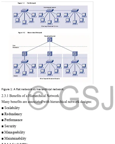
5. Hierarchical Network Model
6. Hierarchical models enable you to design internetworks that use specialization of function combined with a hierarchical organization. Such a design simplifies the tasks required to build a network that meets current requirements and can grow to meet future requirements. Hierarchical models use layers to simplify the tasks for internetworking. Each layer can focus on specific functions, allowing you to choose the right systems and features for each layer. Hierarchical models apply to both LAN and WAN design.
Figure 1: A flat network vs hierarchical network
2.3.1 Benefits of a Hierarchical Network
Many benefits are associated with hierarchical network designs: ■ Scalability
■ Redundancy ■ Performance ■ Security ■ Manageability ■ Maintainability
2.3.1.1 Scalability
access layer switches, you can add additional core layer switches to handle the additional load on the core.
2.3.1.2 Redundancy
As a network grows, availability becomes more important. You can dramatically increase availability through easy redundant implementations with hierarchical networks. Access layer switches are connected to two different distribution layer switches to ensure path redundancy. If one of the distribution layer switches fails, the access layer switch can switch to the other distribution layer switch. Additionally, distribution layer switches are connected to two or more core layer switches to ensure path availability if a core switch fails. The only layer where redundancy is limited is at the access layer. Typically, end node devices, such as PCs, printers, and IP phones, do not have the capability to connect to multiple access layer switches for redundancy. If an access layer switch fails, just the devices connected to that one switch would be affected by the outage. The rest of the network would continue to function unaffected.
2.3.1.3 Performance
Communication performance is enhanced by avoiding the transmission of data through low performing, intermediary switches. Data is sent through aggregated switch port links from the access layer to the distribution layer at near wire speed in most cases. The distribution layer then uses its high-performance switching capabilities to forward the traffic up to the core, where it is routed to its final destination. Because the core and distribution layers perform their operations at very high speeds, no contention for network bandwidth occurs. As a result, properly designed hierarchical networks can achieve near wire speed between all devices.
2.3.1.4 Security
distribution layer switches to process Layer 3 data because they can process it much more efficiently. Canavan, J. E
2.3.1.5 Manageability
Manageability is relatively simple on a hierarchical network. Each layer of the hierarchical design performs specific functions that are consistent throughout that layer. Therefore, if you need to change the functionality of an access layer switch, you could repeat that change across all access layer switches in the network because they presumably perform the same functions at their layer. Deployment of new switches is also simplified because switch configurations can be copied between devices with very few modifications. Consistency between the switches at each layer allows for rapid recovery and simplified troubleshooting. In some special situations, configuration inconsistencies could exist between devices, so you should ensure that configurations are well documented so that you can compare them before deployment.
2.3.1.6 Maintainability
Because hierarchical networks are modular in nature and scale very easily, they are easy to maintain. With other network topology designs, maintainability becomes increasingly complicated as the network grows. Also, in some network design models, there is a finite limit to how large the network can grow before it becomes too complicated and expensive to maintain. In the hierarchical design model, switch functions are defined at each layer, making the selection of the correct switch easier. Adding switches to one layer does not necessarily mean there will not be a bottleneck or other limitation at another layer. For a full mesh network topology to achieve maximum performance, all switches need to be high-performance switches because each switch needs to be capable of performing all the functions on the network. In the hierarchical model, switch functions are different at each layer. You can save money by using less-expensive access layer switches at the lowest layer, and spend more on the distribution and core layer switches to achieve high performance on the network
Benefits of the Hierarchical Model the benefits of using hierarchical models for your network design include the following:
Cost savings
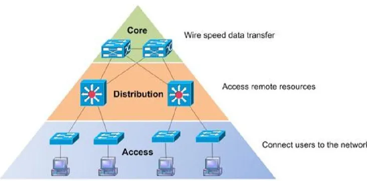
2.4 Hierarchical Network Design
The most important idea concerning the hierarchical network model is the step-by-step construction of the network, which implements one module at a time starting with the foundation. The implementation of each module can be supervised by the network architect, but the details are covered by specialized teams (e.g., routing, security, voice, and so on). This modular approach is the key to simplifying the network.
The core layer provides fast transport between distribution switches within the enterprise campus.
The distribution layer provides policy-based connectivity.
The access layer provides workgroup and user access to the network.
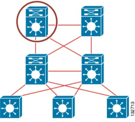
Figure 1: Hierarchical network
The modular network design facilitates modifications in certain modules, after their implementation, and makes it easy to track faults in the network.
that prefix is part of a larger, summarized network whose state does not change. This behavior results in efficiency in network functionality and allows for optimal network design. Cisco Systems, Inc. (2003, March 14)
2.4.1 Core Layer
The core layer is the network’s high-speed switching backbone that is crucial to corporate communications. It is also referred as the backbone. The core layer should have the following characteristics:
Fast transport High reliability Redundancy Fault tolerance
Low latency and good manageability
Avoidance of CPU-intensive packet manipulation caused by security, inspection, quality of service (QoS) classification, or other processes Limited and consistent diameter QoS
When a network uses routers, the number of router hops from edge to edge is called the diameter. As noted, it is considered good practice to design for a consistent diameter within a hierarchical network. The trip from any end station to another end station across the backbone should have the same number of hops. The distance from any end station to a server on the backbone should also be consistent. Limiting the internetwork’s diameter provides predictable performance and ease of troubleshooting. You can add distribution layer routers and client LANs to the hierarchical model without increasing the core layer’s diameter. Use of a block implementation isolates existing end stations from most effects of network growth.
2.4.2 Distribution Layer
The network’s distribution layer is the isolation point between the network’s access and core layers. The distribution layer can have many roles, including implementing the following functions:
Policy-based connectivity (for example, ensuring that traffic sent from a particular network is forwarded out one interface while all other traffic is forwarded out another interface)
Aggregation of WAN connections QoS
Security filtering
Address or area aggregation or summarization Departmental or workgroup access
Broadcast or multicast domain definition Routing between virtual LANs (VLANs)
Media translations (for example, between Ethernet and Token Ring)
Redistribution between routing domains (for example, between two different routing protocols) Demarcation between static and dynamic routing protocols You can use several Cisco IOS Software features to implement policy at the distribution layer:
Filtering by source or destination address Filtering on input or output ports
Hiding internal network numbers by route filtering Static routing
QoS mechanisms, such as priority-based queuing
The distribution layer provides aggregation of routes providing route summarization to the core. In the campus LANs, the distribution layer provides routing between VLANs that also apply security and QoS policies.
2.4.3 Access Layer
The access layer provides user access to local segments on the network. The access layer is characterized by switched LAN segments in a campus environment. Micro segmentation using LAN switches provides high bandwidth to workgroups by reducing the number of devices on Ethernet segments. Functions of the access layer include the following:
Layer 2 switching High availability Port security
Broadcast suppression
Address Resolution Protocol (ARP) inspection Virtual access control lists (VACLs)
Spanning tree Trust classification
Power over Ethernet (PoE) and auxiliary VLANs for VoIP Network Access Control (NAC)
Auxiliary VLANs
You implement high availability models at the access layer. The section “High Availability Network Services” covers availability models. The LAN switch in the access layer can control access to the port and limit the rate at which traffic is sent to and from the port. You can implement access by identifying the MAC address using ARP, trusting the host, and using access lists. Other chapters of this book cover the other functions in the list. For small office/home office (SOHO) environments, the entire hierarchy collapses to interfaces on a single device. Remote access to the central corporate network is through traditional WAN technologies such as ISDN, Frame Relay, and leased lines. You can implement features such as dial-on-demand routing (DDR) and static routing to control costs. Remote access can include virtual private network (VPN) technology.
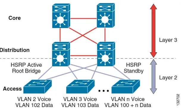
2.5 Migrating the L2/L3 Boundary to the Access Layer
Figure 2: A network with L2 L3 boundary at the distribution
An alternative configuration to the traditional distribution block model illustrated above is one in which the access switch acts as a full Layer 3 routing node (providing both Layer 2 and Layer 3 switching), and the access-to-distribution Layer 2 uplink trunks are replaced with Layer 3 point-to-point routed links. This alternative configuration, in which the Layer 2/3 demarcation is moved from the distribution switch to the access switch appears to be a major change to the design, but is actually simply an extension of the current best practice design. In both the traditional Layer 2 and the Layer 3 routed access design, each access switch is configured with unique voice and data VLANs. In the Layer 3 design, the default gateway and root bridge for these VLANs is simply moved from the distribution switch to the access switch. Addressing for all end stations and for the default gateway remain the same. VLAN and specific port configuration remains unchanged on the access switch. Router interface configuration, access lists, “IP helper”, and any other configuration for each VLAN remain identical, but are now configured on the VLAN Switched Virtual Interface (SVI) defined on the access switch, instead of on the distribution switches. There are several notable configuration changes associated with the move of the Layer 3 interface down to the access switch. It is no longer necessary to configure an HSRP or GLBP virtual gateway address as the “router” interfaces for all the VLANs are now local. Similarly with a single multicast router, for each VLAN it is not necessary to perform any of the traditional multicast tuning such as tuning PIM query intervals or to ensure that the designated router is synchronized with the active HSRP gateway.
Figure 3: A network with L2 L3 boundary at the access
Note in this project the layer 2 and the layer 3 mitigation will be at the access layer. We might not have a lot of configuration on L2 spanning-tree.
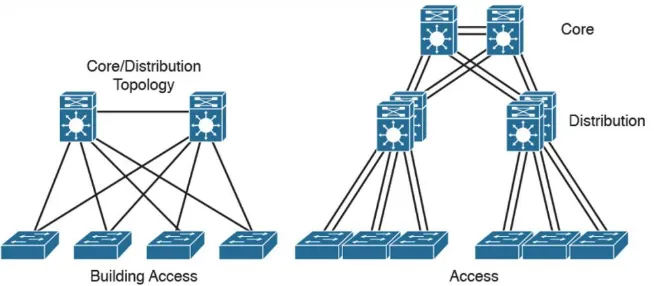
2.6 Collapsed Core Design
One alternative to the three-layer hierarchy is the collapsed core design. It is a two-layer hierarchy used with smaller networks. It is commonly used on sites with a single building with just multiple floors. In this design the core and distribution layers are merged, providing all the services needed for those layers. Design parameters to decide if you need to migrate to the three-layer hierarchy include not enough capacity and throughput at the distribution three-layer, network resiliency, and geographic dispersion.
2.7 The Enterprise Architecture
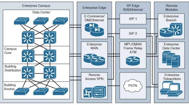
This is a modular approach to network design, this section identifies enterprise architecture modules that are commonly found in medium-to-large organizations. The Enterprise Architecture model facilitates the design of larger, more scalable networks. As networks become more sophisticated, it is necessary to use a more modular approach to design than just WAN and LAN core, distribution, and access layers. The architecture divides the network into functional network areas and modules. These areas and modules of the Enterprise Architecture are
Enterprise campus area Enterprise data center module Enterprise branch module Enterprise teleworker module
Figure 5: An enterprise network 2.8 Summary
The campus hierarchical design help understand the campus LAN and the modular design help understand the whole enterprise network that is, including the LAN WAN and the data center.
Methodology
The methodology used in this project is a very simple one. First in Step 1, decision makers identify requirements, and a conceptual architecture is proposed. This step occurs in the Strategy and Analysis process of the PBM Plan phase. In Step 2, the network is assessed, and a gap analysis is performed to determine the infrastructure necessary to meet the requirements. The network is assessed on function, performance, and quality. In Step 3, the network topology is designed to meet the requirements and close the network gaps identified in the previous steps. A detailed design document is prepared during this phase.
In designing a network
Approach
The best approach in this phase is the top-down approach, which is suitable for a medium-sized network to a large enterprise campus design. Using this approach ensures that you have an overview of the design before focusing on the design details. This basically means beginning with Layer 7 of the OSI model and then moving down from the Application Layer to the Presentation, Session, Transport, Network, Data Link, and Physical Layers.
The network and physical infrastructure should be adapted to the needs of the network applications and services. In other words, you should not choose your network devices or your hardware and software technologies until the requirements for the applications are fully analyzed and met.
The concepts of SONA and IIN should also be incorporated into the design process and combined with the business’s needs and organizational requirements. This includes considering issues such as organizational and technical constraints.
The top-down approach is usually a very time-consuming process and a bit more costly, but it is preferred over bottom-up solutions, where the design is based on previous experience and you are just looking for a quick fix or solution. The problem with the bottom-up approach is finding an inappropriate design in the medium- to long-term in which the organizational requirements and constraints are not included. This could result in process rollbacks at later phases of the project. Jeff Doyle
3.0 Overview of LAN services
In addition to providing the integrated voice, video and data services for the employees, branch offices also require guest network access, and in some cases should support demilitarized zones (DMZs). The guest access can be for partners or customers, and guest access includes both wired and wireless access.
Regardless of the presence of DMZ, security in branch offices is a key element of branch LAN services. The LAN must be protected against malicious attacks, and the users accessing the corporate network must be authorized/authenticated.
This chapter contain some of the most common service found in a campus LAN network. Some of the features to be considered here include
• Layer 2 LAN service • Layer 3 LAN service • Management LAN service • Security LAN service
3.1 LAN Layer 2 Technologies
The following subsections describe the key Layer 2 switching features commonly found in a campus LAN network:
• Layer 2 Addressing
• Switching
• 802.1Q and Layer 2 Protocol Tunneling • CDP
• EtherChannel Bundles • Jumbo Frames
• MST • PVRST+ • QoS
• Spanning Tree Protocol • SSO
• UDLD
3.1.1 Layer 2 Addressing
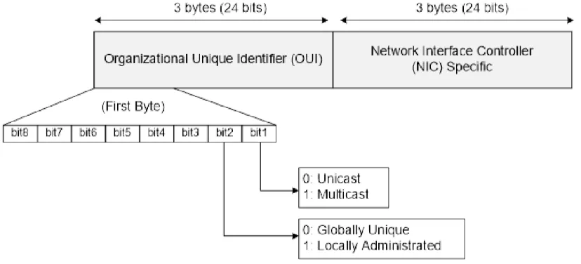
Layer 2 addresses are also called MAC addresses, physical addresses, or burned-in addresses (BIA). These are assigned to network cards or device interfaces when they are manufactured. MAC addresses have a value of 48 bits. The first 24 bits comprise the Organizational Unique Identifier (OUI), which represents a code that identifies the vendor of the device. The second least significant bit in the OUI portion identifies whether the address is locally (bit value of 1) or universally (bit value of 0) assigned, and the most significant bit. Identifies a unicast MAC address (bit value of 0) or a multicast address (bit value of 1). The last 24 bits form a unique value assigned to a specific interface, allowing each network interface to be identified in a unique way via the associated MAC address. Jeff Doyle
Figure 6: MAC Address Structure 3.1.2 Switching
When a frame enters an interface, the switch adds the source MAC address and the source port to its bridging table and then examines the destination MAC. If this is a broadcast, multicast, or unknown unicast frame, the switch floods the frame to all ports, except for the source port. If the source and the destination addresses are on the same interface, the frame is discarded. However, if the destination address is known (i.e., the switch has a valid entry in the bridging table), the switch forwards the frame to the corresponding interface
3.1.3 802.1Q and Layer 2 Protocol Tunneling
802.1Q tunneling is a Q-in-Q technique that expands the VLAN space by retagging the tagged packets that enter the service provider infrastructure. 802.1Q tunneling allows service providers to assign a VLAN to each customer without losing the original customer VLAN IDs inside the tunnel. All data traffic that enters the tunnel is encapsulated with the tunnel VLAN ID. Layer 2 Protocol Tunneling is a similar technique for all Layer 2 control traffic. 802.1Q tunneling and Layer 2 Protocol Tunneling are supported on Supervisor Engine V only.
3.1.4 CDP
The Cisco Discovery Protocol (CDP) is a device-discovery protocol that is both media- and protocol-independent. CDP is available on all Cisco products, including routers, switches, bridges, and access servers. Using CDP, a device can advertise its existence to other devices and receive information about other devices on the same LAN. CDP enables Cisco switches and routers to exchange information, such as their MAC addresses, IP addresses, and outgoing interfaces. CDP runs over the data-link layer only, allowing two systems that support different network-layer protocols to learn about each other. Each device configured for CDP sends periodic messages to a multicast address. Each device advertises at least one address at which it can receive Simple Network Management Protocol (SNMP) messages.
3.1.5 EtherChannel Bundles
3.1.6 Jumbo Frames
The jumbo frames feature allows the switch to forward packets as large as 9216 bytes (larger than the IEEE Ethernet MTU), rather than declare those frames “oversize” and discard them. This feature is typically used for large data transfers. The jumbo feature can be configured on a per-port basis on Layer 2 and Layer 3 interfaces and is supported only on non-blocking GB front ports.
3.1.7 MST
IEEE 802.1s Multiple Spanning Tree (MST) allows for multiple spanning tree instances within a single 802.1Q or Inter-Switch Link (ISL) VLAN trunk. MST extends the IEEE 802.1w Rapid Spanning Tree (RST) algorithm to multiple spanning trees. This extension provides both rapid convergence and load balancing within a VLAN environment.
MST allows you to build multiple spanning trees over trunks. You can group and associate VLANs to spanning tree instances. Each instance can have a topology independent of other spanning tree instances. This new architecture provides multiple forwarding paths for data traffic and enables load balancing. Network fault tolerance is improved because a failure in one instance (forwarding path) does not affect other instances (forwarding paths).
3.1.8 PVRST+
Per-VLAN Rapid Spanning Tree (PVRST+) is the implementation of 802.1w on a per-VLAN basis. It is the same as PVST+ with respect to STP mode and runs RSTP protocol based on 802.1w.
3.1.9 QoS
• Voice, video, and data applications should be classified and marked as close to their sources as possible.
• Unwanted traffic should be policed as close to its source as possible and dropped.
• QoS should be done in hardware; the complexity of the QoS policies to be deployed close to the source dictates the hardware requirements.
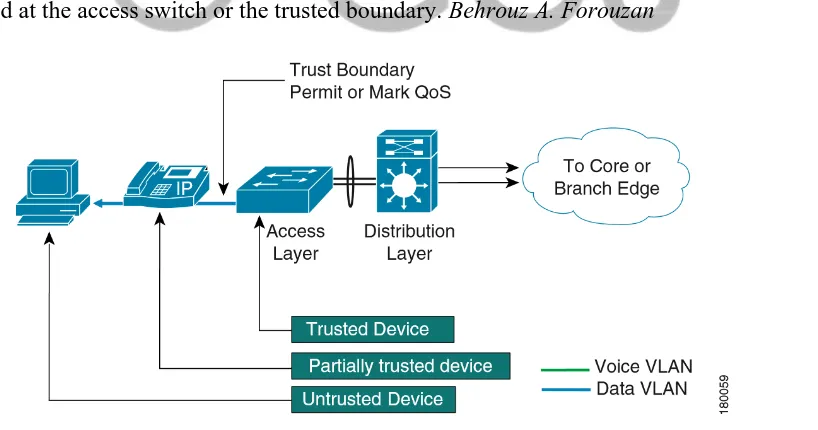
End points are capable of marking class of service (CoS) and Differentiated Services Code Point (DSCP) values. However, it is a matter of policy whether these end points can be trusted. Trusting the device means accepting the markings by these end devices and prioritizing traffic based on those values. If the end devices cannot be trusted, the device closest to the end point can be used to mark the CoS and DSCP values, and also police and rate limit traffic. This closest trusted device that marks the CoS and DSCP values creates a trusted boundary. All these functions require significant CPU time if done in software. Performing these tasks in hardware by ASICs relieves the CPU to do other tasks. As such, the granularity of policing and rate limiting might dictate the use of specific hardware.
It is good practice to let traffic on voice VLANs through without remarking if it is being originated from a Cisco IP phone (Cisco Discovery Protocol running on the access switches determines whether the device is a Cisco IP phone). All other traffic has to be marked or remarked at the access switch or the trusted boundary. Behrouz A. Forouzan
3.1.10 Spanning Tree Protocol
The Spanning Tree Protocol (STP) allows you to create fault-tolerant internetworks that ensure an active, loop-free data path between all nodes in the network. STP uses an algorithm to calculate the best loop-free path throughout a switched network. Campus LAN switch supports the following STP enhancements:
• Spanning tree PortFast—PortFast allows a port with a directly attached host to transition to the forwarding state directly, bypassing the listening and learning states.
• Spanning tree UplinkFast—UplinkFast provides fast convergence after a spanning-tree topology change and achieves load balancing between redundant links using uplink groups. Uplink groups provide an alternate path in case the currently forwarding link fails. UplinkFast is designed to decrease spanning-tree convergence time for switches that experience a direct link failure.
3.1.11 SSO
Stateful switchover (SSO) enables you to propagate configuration and state information from the active to the redundant supervisor engine so that sub-second interruptions in Layer 2 traffic occur when the active supervisor engine switches over to the redundant supervisor engine.
• Stateful IGMP Snooping
This feature propagates the IGMP data learned by the active supervisor engine to the redundant supervisor engine so that when a switchover occurs, the newly active supervisor engine is aware of the multicast group membership, which alleviates a disruption to multicast traffic during a switchover.
• Stateful DHCP Snooping
3.1.12 UBRL
User Based Rate Limiting (UBRL) enables you to adopt microflow policing to dynamically learn traffic flows and rate limit each unique flow to an individual rate. UBRL is available only on the Supervisor Engine V-10GE with the built-in NetFlow support.
3.1.13 UDLD
3.1.14 Unidirectional Ethernet
Unidirectional Ethernet uses only one strand of fiber for either transmitting or receiving one-way traffic for the Gigaport, instead of two strands of fiber for a full-duplex Gigaport Ethernet.
3.1.15 VLANs
Virtual LANs
Virtual LANs (VLANs) define broadcast domains in a Layer 2 network. They represent an administratively defined subnet of switch ports that are in the same broadcast domain, the area in which a broadcast frame propagates through a network.
The following VLAN-related features are also supported.
• VLAN Trunking Protocol (VTP)—VTP maintains VLAN naming consistency and connectivity between all devices in the VTP management domain. You can have redundancy in a domain by using multiple VTP servers, through which you can maintain and modify the global VLAN information. Only a few VTP servers are required in a large network.
• Private VLANs—Private VLANs are sets of ports that have the features of normal VLANs and also provide some Layer 2 isolation from other ports on the switch.
• Private VLAN Trunk Ports—Private VLAN trunk ports allow a secondary port on a private VLAN to carry multiple secondary VLANs.
3.2 Layer 3 Switching Features
A Layer 3 switch is a high-performance switch that has been optimized for a campus LAN or an intranet, and it provides both wirespeed Ethernet routing and switching services. Layer 3 switching improves network performance with two software functions—route processing and intelligent network services. Compared to conventional software-based switches, Layer 3 switches process more packets faster; they do so by using application-specific integrated circuit (ASIC) hardware instead of microprocessor-based engines. The following subsections describe the key Layer 3 switching features on the LAN campus network
• Network Layer Addresses • CEF
• HSRP
• Unidirectional Link Routing • VRF-lite
3.2.1 Network Layer Addresses
Although each network interface has a unique MAC address, this does not specify the location of a specific device or to what network it is attached, meaning a router cannot determine the best path to that device. In order to solve this problem, Layer 3 addressing is used.
3.2.2 IPv4 Addressing
IPv4 addresses are 32-bit numbers represented as strings of 0s and 1s. As mentioned before, the Layer 3 header contains a Source IP Address field and a Destination IP Address field. Each field is 32 bits in length.
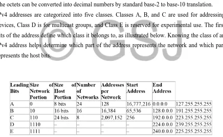
For a more intuitive representation of IPv4 addresses, the 32 bits can be divided into four 4octet (1 octet, or byte, = 8 bits) groupings separated by dots, which is called dotted-decimal notation. The octets can be converted into decimal numbers by standard base-2 to base-10 translation. IPv4 addresses are categorized into five classes. Classes A, B, and C are used for addressing devices, Class D is for multicast groups, and Class E is reserved for experimental use. The first bits of the address define which class it belongs to, as illustrated below. Knowing the class of an IPv4 address helps determine which part of the address represents the network and which part represents the host bits.
Figure 8: Ipv4 address summary 3.2.3 IPv6 Addressing
addresses have a different structure than IPv4 addresses do. They are 128 bits long, which means a larger pool of IPv6 addresses is available. The notation of IPv6 addresses is also different: while an IPv4 address can be written in decimal format, an IPv6 address is notated in a hexadecimal format (i.e., 16 bits separated by colons), for example:
2001:43aa:0000:0000:11b4:0031:0000:c110.
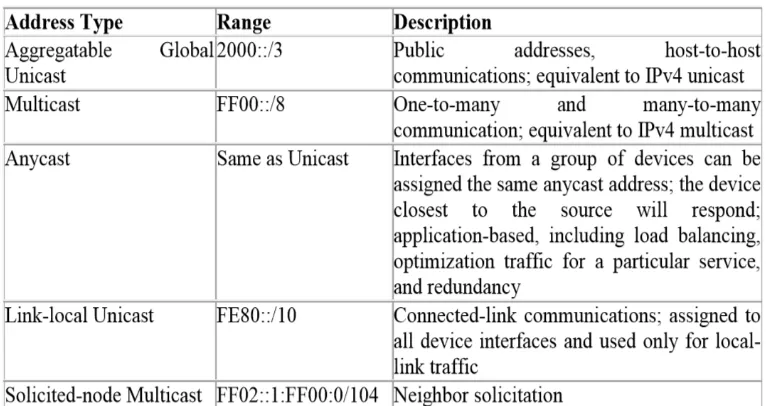
Several types of IPv6 addresses are required for various applications, as listed below. Compared to IPv4 address types (i.e., unicast, multicast, and broadcast) IPv6 is different in that special multicast addresses are used instead of broadcast addressing and it includes a new address type called anycast.
Figure 9: Ipv6 address summary 3.2.4 CEF
3.2.5 HSRP
The Hot Standby Router Protocol (HSRP) provides high network availability by routing IP traffic from hosts on Ethernet networks without relying on the availability of any single Layer 3 switch. This feature is particularly useful for hosts that do not support a router discovery protocol and do not have the functionality to switch to a new router when their selected router reloads or loses power.
3.2.6 IP Routing Protocols
The following routing protocols are supported in most campus LAN networks • RIP
• OSPF • IS-IS • IGRP • EIGRP • BGP
3.2.6.1 RIP
RIP is a standardized vector distance routing protocol and uses a form of distance as hop count metric. It is a distance vector. Through limiting the number of hop counts allowed in paths between sources and destinations, RIP prevents routing loops. Typically, the maximum number of hops allowed for RIP is 15. However, by achieving this routing loop prevention, the size of supporting networks is sacrificed. Since the maximum number of hop counts allowed for RIP is 15, as long as the number goes beyond 15, the route will be considered as unreachable.
3.2.6.2 OSPF
• This protocol is open, which means that its specification is in the public domain. It means that anyone can implement it without paying license fees. The OSPF specification is published as Request For Comments (RFC) 1247.
• OSPF is based on the SPF algorithm, which is also referred to as the Dijkstra’s algorithm, named after the person credited with its creation.
• OSPF is a link-state routing protocol that calls for the sending of link-state advertisements (LSAs) to all other routers within the same hierarchical area. Information on attached interfaces, metrics used, and other variables are included in OSPF LSAs. As a link-state routing protocol, OSPF contrasts with RIP, which are distance-vector routing protocols. Routers running the distance-vector algorithm send all or a portion of their routing tables in routing-update messages only to their neighbors.
3.2.6.3 IS-IS
The Intermediate System-to-Intermediate System Protocol (IS-IS Protocol) uses a link-state routing algorithm. It closely follows the Open Shortest Path First (OSPF) routing protocol used within the TCP/IP environment. The operation of ISO IS-IS Protocol requires each router to maintain a full topology map of the network (that is, which intermediate systems and end systems are connected to which other intermediate systems and end systems). Periodically, the router runs an algorithm over its map to calculate the shortest path to all possible destinations. The IS-IS Protocol uses a two-level hierarchy.
3.2.6.4 IGRP
The Interior Gateway Routing Protocol (IGRP) is a robust distance-vector Interior Gateway Protocol (IGP) developed by Cisco to provide for routing within an autonomous system (AS). Distance vector routing protocols request that a switch send all or a portion of its routing table data in a routing update message at regular intervals to each of its neighboring routers. As routing information proliferates through the network, routers can calculate distances to all nodes within the internetwork. IGRP uses a combination of metrics: internetwork delay, bandwidth, reliability, and load are all factored into the routing decision.
3.2.6.5 EIGRP
Protocol is designed to support IPv4 addresses that IGRP could not support. Hybrid routing protocol incorporates advantages of both Link-state and Distance-Vector routing protocols, Metric is used to determine whether the chosen route is optimized. EIGRP metric is based on its bandwidth, delay, reliability, load and MTU. A default expression for EIGRP metric is 𝑀𝑒𝑡𝑟𝑖𝑐 =
𝐵𝑎𝑛𝑑𝑊𝑖𝑑𝑡ℎ+𝐷𝑒𝑙𝑎𝑦∗256.
There are four basic components to operate EIGRP, which are
Since EIGRP updates are triggered when there is a change, it is important to have a process that routers dynamically learn of other routers on directly connected network. A router should discover once a neighboring router is unreachable of inoperative. Neighbor Discovery and Recovery is accomplished by sending small Hello packets periodically at low cost. Once the hello packets are received, whether this neighbor is alive can be determined. The neighboring router will start exchanging information when routers are functioning.
3.2.6.6 BGP
The Border Gateway Protocol (BGP) is an exterior gateway protocol that allows you to set up an interdomain routing system to automatically guarantee the loop-free exchange of routing information between autonomous systems. In BGP, each route consists of a network number, a list of autonomous systems that information has passed through (called the autonomous system path), and a list of other path attributes.
3.2.7 Multicast Services
Multicast services save bandwidth by forcing the network to replicate packets only when necessary and by allowing hosts to join and leave groups dynamically. The following multicast services are supported:
3.2.8 Policy-Based Routing
Traditional IP forwarding decisions are based purely on the destination IP address of the packet being forwarded. Policy Based Routing (PBR) enables forwarding based upon other information associated with a packet, such as the source interface, IP source address, Layer 4 ports, and so on. This feature allows network managers more flexibility in how they configure and design their networks.
3.2.9 Unidirectional Link Routing
Unidirectional link routing (UDLR) provides a way to forward multicast packets over a physical unidirectional interface (such as a satellite link of high bandwidth) to stub networks that have a back channel.
3.2.10 VRF-lite
VPN routing and forwarding (VRF-lite) is an extension of IP routing that provides multiple routing instances. Along with BGP, it enables the creation of a Layer 3 VPN service by keeping separate IP routing and forwarding tables for each VPN customer. VRF-lite uses input interfaces to distinguish routes for different VPNs. It forms virtual packet-forwarding tables by associating one or more Layer 3 interfaces with each VRF, allowing the creation of multiple Layer 3 VPNs on a single switch. Interfaces in a VRF could be either physical, such as an Ethernet port, or logical, such as a VLAN switch virtual interface (SVI). However, interfaces cannot belong to more than one VRF at any time.
3.3 Management Features
The Catalyst 4500 series switch offers network management and control through the CLI or through alternative access methods, such as SNMP. The switch software supports these network management features:
• Cisco Network Assistant and Embedded • Dynamic Host Control Protocol
• Forced 10/100 Autonegotiation • Intelligent Power Management • NetFlow Statistics
• Simple Network Management Protocol • SPAN and RSPAN
3.3.1 Cisco Network Assistant and Embedded CiscoView
Cisco Network Assistant manages standalone devices, clusters of devices, or federations of devices from anywhere in your intranet. Using its graphical user interface, you can perform multiple configuration tasks without having to remember command-line interface commands. Embedded CiscoView is a device management application that can be embedded on the switch flash and provides dynamic status, monitoring, and configuration information for your switch. Visual port status information—The switch LEDs provide visual management of port- and switch-level status.
3.3.2 Dynamic Host Control Protocol
The modern switch uses DHCP in the following ways:
• Dynamic Host Control Protocol server—The Cisco IOS DHCP server feature is a full DHCP server implementation that assigns and manages IP addresses from specified address pools within the router to DHCP clients. If the Cisco IOS DHCP server cannot satisfy a DHCP request from its own database, it can forward the request to one or more secondary DHCP servers defined by the network administrator.
3.3.3 Forced 10/100 Autonegotiation
This feature allows you to configure a port to limit the speed at which it will autonegotiate to a speed lower than the physically maximum speed. This method of reducing the throughput incurs much less overhead than using an ACL.
3.3.4 Intelligent Power Management
3.3.5 NetFlow Statistics
NetFlow Statistics is a global traffic monitoring feature that allows flow-level monitoring of all IPv4-routed traffic through the switch. Both routed and switched IP flows are supported. For more information on NetFlow statistics, see Chapter 38, “Configuring NetFlow.”
3.3.6 Secure Shell
Secure Shell (SSH) is a program that enables you to log into another computer over a network, to execute commands remotely, and to move files from one machine to another. The switch may not initiate SSH connections: SSH will be limited to providing a remote login session to the switch and will only function as a server.
3.3.7 Simple Network Management Protocol
Simple Network Management Protocol (SNMP) facilitates the exchange of management information between network devices. LAN switch supports these SNMP types and enhancements:
• SNMP—A full Internet standard
• SNMP v2—Community-based administrative framework for version 2 of SNMP
• SNMP v3—Security framework with three levels: noAuthNoPriv, authNoPriv, and authPriv • SNMP trap message enhancements—Additional information with certain SNMP trap messages, including spanning-tree topology change notifications and configuration change notifications
3.3.8 SPAN and RSPAN
Switched Port Analyzer (SPAN) allows you to monitor traffic on any port for analysis by a network analyzer or Remote Monitoring (RMON) probe. You also can do the following:
• Configure ACLs on SPAN sessions.
• Allow incoming traffic on SPAN destination ports to be switched normally.
• Explicitly configure the encapsulation type of packets that are spanned out of a destination port. • Restrict ingress sniffing depending on whether the packet is unicast, multicast, or broadcast, and depending on whether the packet is valid.
3.4 Security Features
Most modern LAN switch offers network management and control through the CLI or through alternative access methods, such as SNMP. The switch software supports these security features: • Network Security with ACLs
• 802.1X Identity-Based Network Security • Dynamic ARP Inspection
• Dynamic Host Configuration Protocol Snooping • Flood Blocking
• IP Source Guard
• Local Authentication, RADIUS, and TACACS+ Authentication • Network Security with ACLs
• Port Security • Storm Control • Utilities
3.4.1 Network Admission Control (NAC)
NAC supports consists of two features: • NAC Layer 2 IP Validation
NAC L2 IP is an integral part of Cisco Network Admission Control. It offers the first line of defense for infected hosts (PCs and other devices attached to a LAN port) attempting to connect to the corporate network. NAC L2 IP on the Cisco Catalyst 4500 Series performs posture validation at the Layer 2 edge of the network for non-802.1x-enabled host devices. Host device posture validation includes anti-virus state and OS patch levels. Depending on the corporate access policy and host device posture, a host may be unconditionally admitted, admitted with restricted access, or quarantined to prevent the spread of viruses across the network
• NAC Layer 2 802.1X Authentication
The Cisco Catalyst 4500 Series extends NAC support to 802.1x-enabled devices. Like NAC L2 IP, the NAC L2 802.1x feature determines the level of network access based on endpoint information.
3.4.2 802.1X Identity-Based Network Security
• 802.1X protocol—This feature provides a means for a host that is connected to a switch port to be authenticated before it is given access to the switch services.
• 802.1X with VLAN assignment—This feature enables you to enable non-802.1X-capable hosts to access networks that use 802.1X authentication.
• 802.1X authentication for guest VLANs—This feature enables you to use VLAN assignment to limit network access for certain users.
3.4.3 Dynamic ARP Inspection
Dynamic ARP Inspection (DAI) intercepts all ARP requests, replies on untrusted ports, and verifies each intercepted packet for valid IP to MAC bindings. Dynamic ARP Inspection helps to prevent attacks on a network by not relaying invalid ARP replies out to other ports in the same VLAN. Denied ARP packets are logged by the switch for auditing.
3.4.4 Dynamic Host Configuration Protocol Snooping
Dynamic Host Configuration Protocol (DHCP) Snooping is a security feature that is a component of a DHCP server. DHCP snooping provides security by intercepting untrusted DHCP messages and by building and maintaining a DHCP snooping binding table. An untrusted message is a message that is received from outside the network or firewall that can cause traffic attacks within your network.
3.4.5 Flood Blocking
Flood blocking enables users to disable the flooding of unicast and multicast packets on a per-port basis. Occasionally, unknown unicast or multicast traffic from an unprotected per-port is flooded to a protected port because a MAC address has timed out or has not been learned by the switch.
3.4.6 IP Source Guard
3.4.7 Local Authentication, RADIUS, and TACACS+ Authentication
RADIUS and TACACS+ control access to the switch
3.4.8 Network Security with ACLs
An access control list (ACL) filters network traffic by controlling whether routed packets are forwarded or blocked at the router interfaces. The LAN switch examines each packet to determine whether to forward or drop the packet based on the criteria you specified within the access lists. MAC access control lists (MACLs) and VLAN access control lists (VACLs) are supported. VACLs are also known as VLAN maps in Cisco IOS. The following security features are supported:
• MAC address filtering, which enables you to block unicast traffic for a MAC address on a VLAN interface.
• Port ACLs, which enable you to apply ACLs to Layer 2 interfaces on a switch for inbound traffic. For information on ACLs, MACLs, VLAN maps, MAC address filtering, and Port ACLs.
3.4.9 Port Security
3.4.10 Storm Control
Broadcast suppression is used to prevent LANs from being disrupted by a broadcast storm on one or more switch ports. A LAN broadcast storm occurs when broadcast packets flood the LAN, creating excessive traffic and degrading network performance. Errors in the protocol-stack implementation or in the network configuration can cause a broadcast storm. Multicast and broadcast suppression measures how much broadcast traffic is passing through a port and compares the broadcast traffic with some configurable threshold value within a specific time interval. If the amount of broadcast traffic reaches the threshold during this interval, broadcast frames are dropped, and optionally the port is shut down.
3.4.11 Utilities
3.4.11.1 Layer 2 Traceroute
Layer 2 Traceroute allows the switch to identify the physical path that a packet takes from a source device to a destination device. Layer 2 traceroute supports only unicast source and destination MAC addresses.
3.4.11.2 Time Domain Reflectometry
3.4.11.3 Debugging Features
The Catalyst 4500 series switch has several commands to help you debug your initial setup. These commands are included in the following groups:
• platform • debug platform
3.5 Summary
In a computer network, the transmission of data is based on the routing protocol which selects the best routes between any two nodes. Different types of routing protocols are applied to specific network environment. Three typical types of routing protocol are chosen as the simulation samples: RIP, OSPF and EIGRP. RIP (Routing Information Protocol) is one of the oldest routing protocols still in service. Hop count is the metric that RIP uses and the hop limit limits the network size that RIP can support. OSPF (Open Shortest Path First) is the most widely used IGP (Interior Gateway Protocol) large enterprise networks. OSPF is based on the Shortest Path First (SPF) algorithm which is used to calculate the shortest path to each node. EIGRP Enhanced Interior Gateway Routing Protocol) is Cisco's proprietary routing protocol based on Diffusing Update Algorithm. EIGRP has the fastest router convergence among all the protocols stated in this chapter.
IMPLIEMTATION AND RESULT 4.0 Introduction
4.1 Core Switch Configuration (EIGRP)
Figure 10:A Core switch with EIGRP
To successfully configure EIGRP on the core switch one the following steps must be properly consider. For better understanding visit the appendix of this project
! configure key chain for authentication ! Enabled spanning tree as a fail-safe practice ! spanning-tree mode rapid-pvst
! make sure of redundancy
! Configure necessary loopback interfaces to support Multicast MSDP and Anycast for ! enable quality of service on all interface
! RP redundancy
! Configure point to point links to Distribution switches
! Reduce carrier delay to 0. Tuning carrier delay no longer has an impact on GigE and ! 10GigE interfaces but is recommended to be configured as a best practice for network ! operational consistency
! Configure trust DSCP to provide for maximum granularity of internal QoS queuing ! configure eigrp with AS 100
4.2 Distribution Switch Configuration (EIGRP)
Figure 11: A Distribution switch with eigrp
To successfully configure EIGRP on the distribution switch one the following steps must be properly consider. For better understanding visit the appendix of this project
! configure key chain for authentication
!Configure spanning tree as a redundant protective mechanism ! spanning-tree mode rapid-pvst
! spanning-tree loopguard default
! Configure point to point Layer 3 links to each of the access switches ! enable quality of service on all interface required
! configure EIGRP with AS 100
Figure 12: An Access switch with eigrp
To successfully configure EIGRP on the access switch one the following steps must be properly consider. For better understanding visit the appendix of this project
! configure key chain for authentication ! spanning-tree mode rapid-pvst
! spanning-tree loopguard default ! Create a local Data and Voice VLAN
! Configure an RP sink hole for non-authorized Multicast groups
! Define the uplink to the Distribution switches as a point to point Layer 3 link ! Reduce EIGRP hello and dead timers to 1 and 3 seconds>
! Enable EIGRP MD5 authentication>
! Define Switched Virtual Interfaces’s for both access Data and Voice VLANs
! Configure EIGRP as an EIGRP stub router, advertising connected routes upstream to the distribution
! configure EIGRP with AS 100
Figure 13: A core switch with Ospf
The configurations for OSPF is a little more cumbersome than that of EIGRP on the core but in the end one should be able to achieve similar result if all the configuration are done properly. The following configuration should be consider in designing an OSPF core switch.
! Enabled spanning tree as a fail-safe practice ! spanning-tree mode rapid-pvst
! spanning-tree loopguard default ! redundancy
! Configure necessary loopback interfaces to support Multicast MSDP and Anycast for ! RP redundancy
! Configure point to point links to Distribution switches
! Configure IP Event Dampening on all links using sub-second timers and/or switches configured with sub-second
! LSA or SPF throttle timers Dampening
! Reduce carrier delay to 0. Tuning carrier delay no longer has an impact on GigE and 10GigE interfaces but is recommended to be configured as a best practice for network operational consistency
! Configure trust DSCP to provide for maximum granularity of internal QoS queuing mls qos trust dscp
! router ospf 100
! Explicitly configure the OSPF router id as a best practice when using Anycast and/or any identical loopback address on multiple routers.
! Modify the reference BW to support 10GigE links auto-cost reference-bandwidth 10000 ! Reduce the SPF and LSA Throttle timers
! Passive all interfaces not intended to form OSPF neighbors ! Multicast route point and MSDP configuration.
4.5 Distribution Switch Configuration (OSPF)
Figure 14: A distribution switch ospf
! Configure IP Event Dampening on all links using sub-second timers and/or switches configured
with sub-second
! Use of /31 addressing on point to point links optimizes use of IP address space in the campus ! Reduce OSPF hello and dead timers to 250 msec and 1 second. In a point-point L3 campus design the OSPF timers are not the primary mechanism used for link and node failure detection. They are intended to provide a fail-safe mechanism only. Reduce carrier delay to 0. Tuning carrier delay no longer has an impact on GigE and 10GigE interfaces but is recommended to be configured as a best practice for network operational consistency carrier-delay msec 0
! Configure trust DSCP to provide for maximum granularity of internal QoS queuing mls qos trust dscp
! Configure point to point L3 links to each of the core switches. Follow same interface configuration as specified on links to access switches
! Configure point to point L3 links to the peer distribution switch. Follow same interface configuration as
! specified on links to access switches
! Explicitly configure the OSPF router id as a best practice when using Anycast and/or any identical loopback address on multiple routers.
! Modify the reference BW to support 10GigE links auto-cost reference-bandwidth 10000
! Configure distribution block area as a totally stubby area to reduce the number of LSA and routes in the access switches
! Summarize the distribution block subnets into a single route advertized into area 0 core ! Reduce the SPF and LSA Throttle timers
! Define distribution block area and core area
Figure 15: An access switch with Ospf
! Configure spanning tree as a redundant protective mechanism ! spanning-tree mode rapid-pvst
! spanning-tree loopguard default ! redundancy
! Create a local Data and Voice VLAN
! Configure an RP sink hole for non-authorized Multicast groups
! Define the uplink to the Distribution switches as a point to point Layer 3 link
! Configure IP Event Dampening on all links using sub-second timers and/or switches configured with sub-second LSA or SPF throttle timers Dampening
! Use of /31 addressing on point to point links optimizes use of IP address space in the campus ! Reduce OSPF hello and dead timers to 250 msec and 1 second. In a point-point L3 campus design the OSPF timers are not the primary mechanism used for link and node failure detection. They are intended to provide a fail-safe mechanism only.
5.0 CONCLUSION
It is easy to notice that the configuration required by EIGRP is shorter than the configuration required by OSPF this is because EIGRP was designed to have a very simple configuration, although EIGRP used to be CISCO propitiate now it has been release to the public for use. So if you think OSPF is too bulky for you as a network admin, then feel free to use EIGRP as an alternative.
5.1 RECOMMENDETION
First off I’d recommend that enterprise in Lagos leverage the hierarchical campus approach because it can help in saving cost, its ease to understand, it supports Modular network growth and it improve fault isolation in the overall network.
REFERENCES
1. “Scalable Routing Design Principles,” RFC 2792, https://tools.ietf.org 2. “The Accumulated IGP Metric Attribute for BGP,” https://tools.ietf.org 3. “The Evolution of the Next Generation Network,” http://www.ciscolive.com
4. “The Journey from CAPEX through TCO to Business Value,” http://www.cisco.com 5. “WAN Architectures and Design Principles,” http://www.ciscolive.com
6. http://digitalcommons.uncfsu.edu/cgi/viewcontent.cgi?article=1011&context=macsc_wp 7. http://phucchau.tran.free.fr/book/O%27Reilly%20%20Managing%20Ip%20Networks%2
0With%20Cisco%20Routers.pdf
8. http://www.cisco.com/c/en/us/td/docs/net_mgmt/active_network_abstraction/37/referenc e/guide/ANARefGuide37.pdf
9. http://www.cisco.com/en/US/netsol/ns815/networking_solutions_program_home.html 10.Hubert Pun, “Convergence Behavior of RIP and OSPF Network Protocols”. Retrieved in
Dec 2001. Internet: http://www2.ensc.sfu.ca/~ljilja/cnl/pdf/hubert.pdf
11.Jeff Doyle, “Routing TCP/IP (Volume I)”, Cisco Systems Press. Chapter 5-9. Published in 1997. Internet: http://www.net130.com/tutorial/cisco-pdf/routingtcpipv1.pdf
12.LAN Baseline Architecture Branch Office Network Reference Design Guidehttp://www.cisco.com/en/US/docs/solutions/Enterprise/Branch/Design.html. 13.M. Medard, Network Reliability and Fault Tolerance (MIT).
14.McQuerry, S. (2004, April 9). CCNA Self-Study: Network Media (The Physical Layer). Retrieved March 25, 2016,
15.OSPF Version 2, RFC 2328, http://www.ietf.org
16.P. Oppenheimer. Top-Down Network Design, Second Edition (Cisco Press).
17.Pankaj Rakheja, Prabhjot Kaur, Anjali Gupta, Aditi Sharma, “Performance Analysis of RIP, OSPF, IGRP and EIGRP Routing Protocols in a Network”. Retrieved on June 18, 2012. Internet: http://research.ijcaonline.org/volume48/number18/pxc3880401.pdf 18.R. White, D. Slice, and A. Retana. Optimal Routing Design (Cisco Press).
19.Scalable Routing Design Principles, RFC 2791, http://www.ietf.org
21.Sedayao, J. (2001). Cisco IOS access lists. " O'Reilly Media, Inc.".