Analysis of Electro-Mechanical Generator Casing
by using Finite Element Method
Sidhu Shelke Prof. P. M. Ravanan
PG Student Associate Professor
Department of Production Engineering Department of Production Engineering
V.J.T.I. Matunga , Mumbai V.J.T.I. Matunga , Mumbai
Abstract
The purpose of this paper is to present basic functional parameters to design and analysis Electro-Mechanical generators casing. The emphasis is put on analytical concepts that determine the engineering solutions to the problem of efficient generation and control of high voltage power required to drive the system. Attention is paid that influence such factors as size, stiffness, and reliability of a housing. Further investigates the role and function of basic components, such as power supply, inverter, and pcb’s. Essential electronic circuits of generator system are then examined, including requirement of voltage, current and timing of electrical power delivery. Finally, issues related to efficient feedback control, including basic design of casing are reviewed. Design optimization is an important of the product development process of electro-mechanical industry. The overall goal is to discover various alternative designs with improved physical or aesthetic properties. In today’s market, most companies design to create new products. Product development mainly believes on product quality and reduces cycle time. However, most techniques limit innovation. They modify a single reference product, which closely matches user needs, and only introduce new products when major conflicts exist between user needs and existing competitor products. This study introduces a new design for product innovation approach. The approach combines two or more distinct reference designs into a single new product. The process created using various processes to perform smooth development of new product. At the same time, the approach uses structured redesign techniques and structured design principles to overcome the conflicts arise during product lifecycle, which improves solution quality and better performance.
Keywords: Casing, Base panel, Top panel, Tray1, Front panel
________________________________________________________________________________________________________
I. INTRODUCTION
(IJSTE/ Volume 2 / Issue 12 / 094)
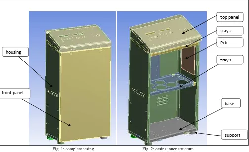
Fig. 1: complete casing Fig. 2: casing inner structure
Designing casing makes consideration lot of data regarding pcb dimensions, effect of hardware, cost involved to make product, time involved to develop whole system. Various shape deformation techniques drastically simplify the creation of design variations; their successful application within practical design optimization tasks comes with a number of challenges: 1) Severe defects in the given data or varying element types in the simulation’s surface and volume meshes prohibit
surface-based deformation techniques and typically require space deformation methods.
2) The results obtained from the deformation might not be of sufficient quality or up to required, as illustrated in the comparisons of Staten and colleagues [1] and our recent investigations [2,3], which suggest the use of tri harmonic radial basis functions for high quality shape deformations.
3) The technique might not offer adequate level of modelling flexibility, e.g., to simulate inhomogeneous material behaviour during deformation. Which implicitly minimize bending-type energies; fail to simulate stretching-dominant materials? 4) Critical and important features required for functionality and realization of design prototypes during product development
might not be properly preserved during deformation. The typical solution to this spread problem in design optimization is to incorporate additional penalty terms into the optimization process. This strategy, however, results in costly creation and evaluation of unfavourable design variations. But it ensures quality of product based on standards required.
II. COMMONLY USED MATERIAL FOR CASING
This standard casing requirements of cold reduced low carbon steel sheets and strips for bending and drawing purpo se and where the surface is of prime importance[4]. It covers sheets and strips up to 4 mm thick, both in coil form and c ut lengths. Most of Electro-Mechanical devices are made from IS513 CRCA CR2 material which is less costly and easily available [5].
Chemical composition of CRCA CR2 Material Constituent, Percent, Max
carbon Manganese sulphur Phosphorus 0.12 0.50 0.035 0.040 Mechanical Properties at Room Temperature
Yield Stress (Mpa) Tensile Stress (Mpa) Elongation, Min Hardness, Max
CR2 240 370 L (i)=30 L(o)=37 HRD=65 HR=60
III. CALCULATION ON CASING
Dimension of casing (height) 950mm x (width) 500mm x (depth) 300mm Mass of Front Panel MFP =6 Kg
housing
front panel
top panel
tray 1
base
support Pcb
Figure1: complete casing Figure2:casing inner structure
Mass of Top panel MTP=2.5 Kg
Mass of Tray1 MT1=15Kg (Including all Pcb and hardware Mounting)
Mass of Tray2 MT2=2 Kg
Mass of Housing MH=12.5 Kg
Mass of Base Mb=3 Kg
Mass of Power Module on Base MP= 17.5Kg
Total Mass = 41.5Kg
Calculation for Sheet Metal Thickness Considering Safety Factor:
As very least forces get applied on top panel during impact test, hence calculation are done for top panel . Every Electro-Mechanical system casing safety factor need to be 5 (according to ISO standards).
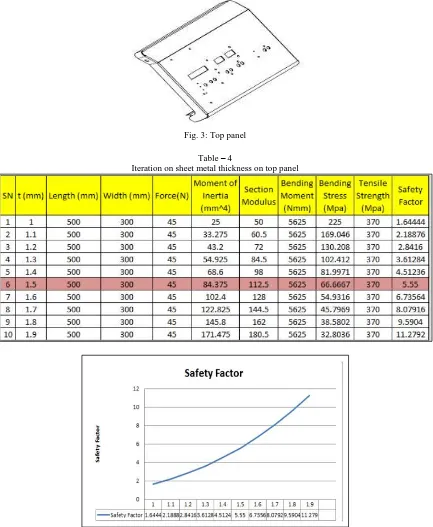
Dimension of top panel 500mm x 300mm, at operating force 45N
Fig. 3: Top panel
Table – 4
Iteration on sheet metal thickness on top panel
(IJSTE/ Volume 2 / Issue 12 / 094)
From calculation in Excel sheet 1.5mm thickness sheet is giving S.F near to 5. To reduce overall cost of casing it is always common thickness is considered.
Following are the Factors which directly affect the cost of Casing:
1) Nesting of sheet metal: It is always preferred to use common thickness which directly decreases wastage factor of sheet saving sheet cutting.
2) Bending and welding operation: Bending with common bend radius decreases tool step-up cost . 3) Transportation of Finish part to assembly line
4) Labour cost [6].
5) Powdering cost and Hardware cost.
Calculation for Tray1 part:
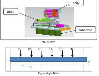
Figure shown Tray1 used in generator is loaded with various capacitor and inductor each weight of capacitor is about 1.5kg there are total 6 capacitor which indicates safety of factor should be more for safety during high impact.
Fig. 6: Tray1
Fig. 6: single Beam
Force(1,2,3,4,5,6)=1.5*9.81N
F(impact acting at centre point of Tray)=20*9.81N
considering forces in one plane to calculate in 2Diemension for 2mm thickness , reaction forces at 2 and 1
R2 = 𝐹1.𝑑1+𝐹2.𝑑2+𝐹3.𝑑3+𝐹5.𝑑5+𝐹6.𝑑6
𝐿 = 42.612N
R1=F1+F2+F3+F4+F5+F6-R2= 42.116N Bending Moment at point 2
M2 =R1.L -F6.d6-F5.d5-F4.d4-F3.d3-F2.d2-F1.d1 -F(impact).d(impact) =-6.67KNmm Bending Stress = 𝑀2
𝑀.𝐼/0.5𝑥𝑡=-46.942Mpa
safety factor = 370(tensile strength crca )/46.942 = 7.8 same technique is for calculating S.F of individual part
Plug Welding Calculation:
weld strength Ws= 230Mpa
shear strength of weld = 0.577 x Ws = 132.71Mpa
weld diameter used for plug weld = 8mm number of weld point nw= 2
total load on plug weld = M (part) x 20g (for impact test) area of weld = (3.14/4) x d^2 = 50.265 mm^2
shear stress = 𝐹 𝑝𝑎𝑟𝑡
safety factor = 𝑠ℎ𝑒𝑎𝑟 𝑠𝑡𝑟𝑒𝑛𝑔𝑡ℎ 𝑜𝑓 𝑤𝑒𝑙𝑑
𝑠ℎ𝑒𝑎𝑟 𝑠𝑡𝑟𝑒𝑠𝑠 = 5.442
Thus S.F shows weld point is in safe zone for impact test
IV. ANALYSIS OF COMPLETE HOUSING AND INDIVIDUAL PARTS USING ANSYS15SOFTWARE
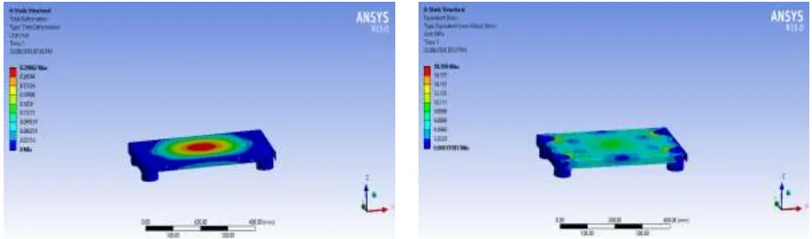
Ansys are carried out on 1.5mm thickness
Fig. 7: Total deformation for 1.5mm Thickness Fig. 8: Equivalent Stress developed in total housing
Analysis on control housing in static structure shows casing designed for 1.5mm thickness is in calculated safety factor.
Analysis of Tray1:
Fig. 9: Total deformation Fig. 10: Equivalent stress developed
Tray1 part which is loaded with many weight sustain for 2mm thickness of CRCA CR2 sheet metal thickness. Analysis need to carry out considering impact force developed during transportation.
Analysis of Base:
(IJSTE/ Volume 2 / Issue 12 / 094)
V. CONCLUSION
In this paper some significant aspects Electro-Mechanical system casing is discussed. Analysis is carried out on total casing and critical individual parts using Ansys 15 software, by using finite element method design are optimized. The results represents that by integrating Analysis will be highly beneficial. Use of advanced technology in design, accuracy of design is improved. Many design related problems which are complicated to determine by traditional methods are eliminated.
REFERENCES
[1] M. L. Staten, S. J. Owen, S. M. Shontz, A. G. Salinger, T. S. Coey, A comparison of mesh morphing methods for 3D shape optimization, in Proceedings of the 20th International Meshing Roundtable, 2011, pp. 293–311.
[2] D. Sieger, S. Menzel, M. Botsch, High quality mesh morphing using triharmonic radial basis functions, in: Proceedings of the 21st International by Meshing Roundtable, Springer-Verlag, Berlin, 2012, pp. 1–15.
[3] D. Sieger, S. Menzel, M. Botsch, On shape deformation techniques for simulation-based design optimization, in: New Challenges in Grid Generation and Adaptivity for Scientific Computing, SEMA SIMAI Springer Series, Springer Milan, 2014, to appear.
[4] Boothroyd, G., Dewhurst, P., “Sheet Metalworking: Material Selection and Process Costing”, Wakefield, 1990. [5] Cold reduced low carbon steel sheet and strip (Fifth Revision), Bureau of Indian Standards, April 2008, p2-5. [6] Wierda, L. S., “Cost Information Tool for Designers”, Dissertation, TU Delft (NL), 1990.
[7] GILMORE, P.C., and GOMOSY, R.C., 1961, Alinear programming approach to the cutting stock problem. Operations Research, 9, 724-746.
[8] Hopper, E. and Turton, B.C.H., 2002, An empirical investigation of metaheuristic and heuristic algorithms for a 2D packing problem. Eur. J. OplRes., 128, 34–57.
[9] Kurochi, N. et al.: CAD/CAM System for Sheet Metal Structural Parts: Development and Implementation. Bull. Japan Soc. of Prec. Eng., Vol. 13, No. 3, Sep. 1979.