ISSN (Online): 2320-9364, ISSN (Print): 2320-9356
www.ijres.org Volume 2 Issue 5 ǁ May. 2014 ǁ PP.68-75
Vehicle Recognition at Night Based on Tail LightDetection Using
Image Processing
Hemanth Kumar B K
#1, Aravind Naik
2, Adesh Gowda
3#1 #2 3
CSE Department, Srinivas Institute Of Technology,ValachilMangalore,574143
Abstract—Automatic recognition of vehicles in front can be used as a component of systems for forward
collisions prevention. When driving in dark conditions, vehicles in front are generally visible by their back lights. Present an algorithm that detects vehicles at night using a camera by searching for tail lights. Develop an image processing systems that can efficiently spot vehicles at different distances and in weather and lightning conditions.Keywords: Vehicle recognition,forward collision, driver assist,automotive,image processing.
I.
INTRODUCTION
Vehicle calamity statistics are jarring at night. Despite 60 percent less traffic on the roads, more Than 40 percent of fatal car accidents occur at night. The statistics for collision are 29 percent of crashes due to collisions in united states of America,18 percent in European Union and 30 percent in Asian countries. In European Union 30 percent and in Asia 60 percent in-vehicle fatalities occurs in darkness. [1].
Every year,Thousands of people are injured or killed as a result of vehicle accidents at night time,and in many cases the accident was not the fault of the injured party or the deceased victim.In 2010,more than 600 people lost their lives as the result of a car crash in Chennai circle,with thousands of the others suffering serious or permanent injuries. Also 6 to 10 accidents take place in night time in our Nation. Indian’s share of global accidents: 10 percent[daily Telegraph].Death and injured caused by accidents on Indian’s roads: 1 person dies every 6 minutes; 10 are injured in the same time frame[BBC, Sep 2005].
In developing countries like India, fatality rate(defined as,road accidents death per 10,000 vehicles) is quite high in comparison to developed countries. While in Europe and North America the situation is generally improving many developing countries face a worsening situation.
Pedestrians and cyclists are often the most vulnerable in night time.The developed countries are now on their way to develop intelligent and smart cars that will help the humanity to avoid accidents during night time detect the vehicle by using their lamp pair,the concepts such as morphological processing and light edge detection are used.these concepts come under Digital Image Processing area.[2].
II.
LEGISLATION
World Wide legislation states that rear automotive lights must be Red and placed symmetrically in pairs at the extremities of the rear of the vehicle. These tail lights must be wired so that and they light up whenever the front headlights are activated,and they must be constantly lit. Legislation also states that although tail lights and break lights can be integrated into a single unit,there must be a minimum ratio between they can be easily distinguished. There is no legislation governing the shape of rear automotive lights. Due to the advances in LED technology,light manufactures are departing from conventional break lights. Thus it is important to have a detection method that is shape independent. It has been compulsory for manufactures to include a horizontal bar break light since 1986 in North America and since 1998 in Europe. This is a feature that could possibly be exploited in future systems,as an aid to detection and as a means to differentiate between tail lights and break lights.
III.
STATE OF ART
the entirely hardware based solution described in [11]. No software signal processing is required. A signal is taken directly from the red channel of the RGB sensor, filtered and thresholded in hardware. This method has a zero processing overhead, but is not adaptable.
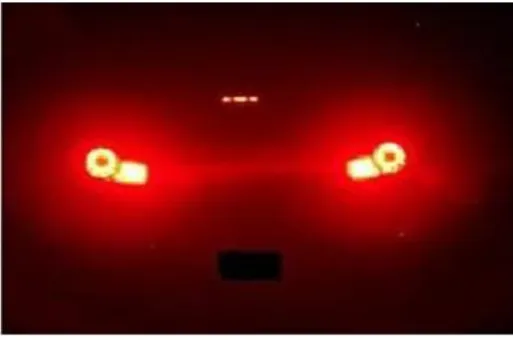
Fig. 1.Tail Lights Cause Camera to Saturate in Places.
Symmetry is commonly used to filter potential candidates for vehicle detection as the rear of a vehicle is generally symmetrical during daylight and darkness. Some approaches fit an axis of symmetry e.g [5]. While compute intensive, this approach is effective for daylight situations where the scene is more complex than darkness.Cucchiara et al [4] detect vehicles under day and night illumination in surveillance video, but approach the two environments with separate techniques. For detection at night, size and shape of thresholded lights are analyzed. An axis of symmetry is determined, and reflections are distinguished from lights by examining the angle of the axis of symmetry. However this would not be effective from a observation point directly behind and square to the target vehicle. Vertical edges and shadows underneath the vehicle along with symmetry and tail light blobs have been used to detect vehicles by day and night in a particle filter framework [2]. The taillight pairing process can be simplified by making several assumptions [10]. They assume that the average car is around 170cm wide and the width/height aspect ratio of a highway vehicle is approximately 2.0.
Morphology has been used to detect vehicle lights [9]. The assumption is made that the lights will be circular or elliptical in shape. However the shape of rear lights is not specified in legislation and automotive designers are experimenting with different shapes as LED lights become more common. A temporal approach can also be used to improve detection rates. Blob trajectories can be grouped by their apparent motion [6], and Kalman filter tracking could be introduced to continue tracking through occlusion [12].
To aid detection, the lane ahead can be detected and a mask applied to reduce the area of the image that is searched for target vehicles [4],[3].
IV.
EXPERIMENTAL DATA CAPTURE
Fig. 2.Architecture of Proposed Work.
Data was captured with different cameras in an effort to assess how sensor independent the system was. However due to the different way in which different sensors interpret colour it was found that the colourfilter parameters of the red threshold had to be slightly adjusted for optimal operation between different sensors. Future work could involve introducing a calibration technique so camera sensors could be changed, and the system less sensor dependant.
A test plan was created with a view to capturing test data in simple situations. The plan involved video sequences with various permutations of the following options.
Street lit environment / no lighting. Tail lights / brake lights.
Indicator lights flashing intermittently. Different distances.
Approaching target vehicle / target vehicle departing.
Real world automotive video data was then captured in urban and rural situations. Data was also taken in bad weather conditions including heavy rain, as detection becomes more challenging when the road surface is wet as rear lights are reflected on it. Algorithm parameters were refined using the experimental test data.
V.
PROPOSED METHODOLOGY
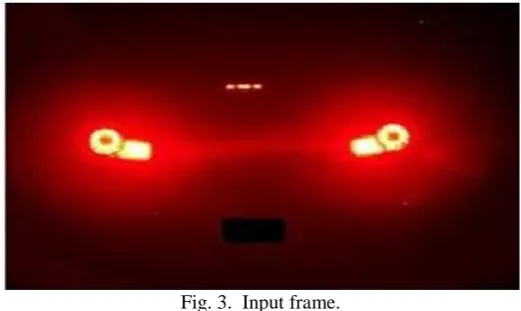
A digital camera fitted in the car captures the front vehicles. The input video is of the form mpeg,avi etc. The captured video is converted into number of frames. The numbers of frames are based on the format of the video.For example AVI files 18 Frames/Sec while MPEG requires 26 frames/Sec to avoid loss of information.
Fig. 3. Input frame. A. Preprocessing
Preprocessing is the process can be carried out into the following list of steps, – Binarization.
In binarization, RGB fames are converted into the binary image. It converts the input image to a binary image. The output image BW replaces all pixels in the input image with luminance greater than level with the value 1 (white) and replaces all other pixels with the value 0 (black).
Fig. 4.Binary Image.
For removing the noise in the binary image, we calculate the weight of the object. Morphological operation employed here for reduce the noise.In Morphological Operation the technique such as erosion and dilation used.Dilation adds pixels to the boundaries of objects in an image, while erosion removes pixels on object boundaries.The number of pixels added or removed from the objects in an image depends on the size and shape of the structuring Elements used to process the image.Erosion is the processes of removing the noise in the input binary frame. Dilation is the process of reconstructing the interesting region that can be eliminated during the time of noise removal.
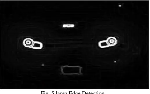
B. Lamp Edge Detection
The noise free input frame are subjected into the edge detection.The Edge Detection block finds the edges in an input image by approximating the gradient magnitude of the image. For edge detection, we use the canny edge detector. The canny Edge Detection block finds edges by looking for the local maxima of the gradient of the input image. It calculates the gradient using the derivative of the Gaussian filter. The Canny method uses two thresholds to detect strong and weak edges. It includes the weak edges in the output only if they areconnected to strong edges. As a result, the method is more robust to noise, and more likely to detect true weak edges. The Canny method applies two thresholds to gradients.A high threshold for low edge sensitivity and a low threshold for high edge sensitivity.Edge starts with the low sensitivity result and then grows it to include connected edge pixels from the high sensitivity results this helps fill in gaps in the detected edges. In this case,the contour functions determine the number contours to display based on the minimum and maximum data values.
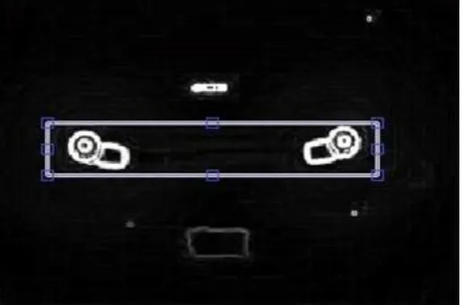
Fig. 5.lamp Edge Detection. C. Lamp Pairing
VI.
DISTANCE MEASURING METHOD
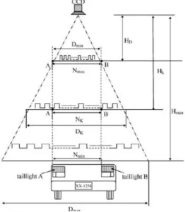
In this section, we discuss a distance measuring principle, which is dependent on a triangle relation formula.We adopt the proportionality of similar triangles for the distance measuring system. First, we assume that the vehicle taillights constitute the two bright spots A and B, as shown in Fig.6.
The length Dmin is the distance between the front edges of the taillights and is constant. When two spots just appear on the extreme edges of the charge-coupled device (CCD) image, assume that the distance between the spots and the CCD camera equals Hd and that the external clock value between the two spots is Nmax.Hmax is the maximum distance we would like to measure. Assume that the external clock value between
Fig. 6.Proportionally of similar between external clock pulse and interval of taillights.
the two spots at the maximum distance Nmin is and that themaximum interval that can be seen in CCD image is Dmax. The relations among DK,NK, and HK are as follows:
DK and Dmax are the lengths of the bases of the triangles formed by the field of view of the CCD, as shown in Fig.6. We assume that Dmin ,Nmax , and are given at initialization. can be easily calculated by . Once is known, we can use (2) to get the distance . Only the external clock values needed to calculate the actual distance.In this brief, the situations of multiple sets of taillights, single or broken taillights, and obscured lights are not considered. The taillight color is assumed to be red.We also assume that the rear of the front vehicle is roughly parallel to the image plane of the camera.
VII.
TAILLIGHT IDENTIFICATION METHOD
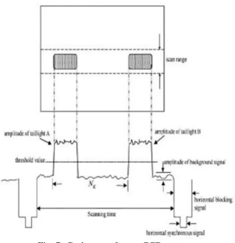
Fig. 7. Red output from a CCD camera.
The circuit structure for identifying the red output signal is a simple and practical circuit as shown in Fig.8. The low-pass filter is used to smooth the signals from the CCD, as shown in Fig.7. Because the lights coming from the taillights are not always pure red and affected by other light sources, the threshold value equals the average background signal, which is produced by passing the red output signal R through a low-pass filter, plus a supplemental quantity.
Fig. 8.Circuit structure for identifying bright signals.
We can define different supplemental quantities for different backgrounds. By adjusting the threshold value and supplemental quantity, the proposed measurement system can be applied in various situations.
The output R of the comparator will produce two positive pulses on a horizontal scanning line as shown in Fig.9. Then,using the two positive pulses as triggers of a counter, the external clock value NK between the two bright spots can be obtained.Given the external clock value, we can transform it to a distance value. From Fig.6, at initialization, we measure the distance between the taillights of a regular car, which constitute the length Dmin, and count the relative interval Nmax. Then, we employ a simple flip-flop, a single-pulse generator, and a counter to obtain Nk. Because Dmin, Nmax, and NK are known, we use (1) to get length.
If is calculated by (1) and HD is given at initialization, we can use (2) to obtain the actual distance HK. In this brief,we propose a technique for transforming the time value scale into a distance scale that uses a clock counter instead of a pixel counter for measuring the distance between the taillights. This method can enhance measurement speed.
VIII.
EXPERIMENTAL RESULTS
In this section, we present experimental results to demon-strate the effectiveness of the proposed system. Example 1: Let Dmin = 103cm and HD = 150cm. is the maximum distance we would like to measure. is the distance from the CCD camera to the taillights. In this experiment, set Hmax to be 810 cm. We use a 12-MHz oscillator to obtain Nmax = 512cm for HD = 150cm. Once we obtain the value of from the circuit.This shows that the proposed image-based distance measuring system is reliable and effective.
Example 2: We redo the experiments using a different CCD camera from that of Example 1. Let Dmin = 103cm and HD = 305cm. Hmax is the maximum distance we would like to measure. HD is the distance from the CCDcamera to the taillights. In this experiment, set Hmax to be 1020 cm. We use a 12-MHz oscillator to obtain for Nmax = 1370cm for HD = 305cm.This shows that the proposed image-based distance measuring system is reliable and effective.
IX.
ASPECT RATIO CONSTRAINTS
As a final check, the width to height aspect ratio of the bounding box containing the tail-lights must meet the following constraints.
X.
RESULTS
This entire process essentially amounts to a symmetry check.If a bounding Box above a certain size is detected then the driver is alerted that a vehicle is close. This section presents some preliminary results drawn from video of a real road environment.In an 12 second sample video of 200 frames,the target vehicle was approximately 10m ahead. The vehicle in 164 of 172 frames, resulting in a detection rate of 98 percent. Bounding boxes resulting from white regions appeared incorrectly,not identifying the target vehicle,4 times in the 200 frames, resulting in a false positive rate of 1.8 percent. These results refer to only a subset of the total video data. The algorithm has demonstrated that it works well in both well lit urban areas and dark rural areas. It also works effectively in wet conditions.
XI.
CONCLUSION
In this paper, we have discussed the need for a system to avoid or mitigate forward collisions during darkness. A background to the relevant automotive rear light legislation, showing characteristics that canbe recognized by image processing, was given. We have presented an algorithm for forward collision detection at night using a visual camera. Our technique filters red and white colours in the HSV colour space. White regions adjacent to red regions are searched for symmetrical pairs, and aspect ratio constraints are applied to resulting bounding boxes. This produces detected rear target vehicle lights. We have shown promising preliminary results, and intend to expand and improve the system. An important next step is to introduce a temporal dimension and track targeted vehicles in video sequences to improve the detection rate, and to detect imminent collisions. It is envisaged to expand the range of test scenarios to make the system more robust.
REFERENCES
[1] W.Y.Wang, M.C.Lu, H.L.Kao, and C.Y.Chu. ”Nighttime Vehicle Distance Measuring Systems”. IEEE Transactions on Circuits
and Systems II;Express Brifs,54,81-85,2005
[2] Y.-M. Chan, S.-S. Huang, L.-C. Fu, and P.-Y. Hsiao. Vehicle detection under various lighting conditions by incorporating
particle filter. In IEEE Intelligent Transporta-tion Systems Conference, pages 534539, 2007.
[3] M. Y. Chern and P. C. Hou. The lane recognition and vehicle detection at night for a camera-assisted car on high-way.
Proceedings ICRA03 IEEE International Conference on Robotics and Automation, vol.2, 2003.
[4] R. Cucchiara and M. Piccardi. Vehicle detection under day and night illumination. Proceedings of the 3rd International ICSC Symposia on Intelligent Industrial Automation and Soft computing, pages 14, June 1999.
[5] Y. Du and N. Papanikolopoulos. Real-time vehicle fol-lowing through a novel symmetry-based approach. Pro-ceedings IEEE
International Conference on Robotics and Automation, 4:31603165, 1997.
[6] C. Juli‘a, A. Sappa, F. Lumbreras, J. Serrat, and A. Lopez. Motion segmentation from feature trajectories with miss-ing data. In
3rd Iberian Conference on Pattern Recognition and Image Analysis,LNCS vol.1, pp., Girona, Spain, June, 2007.
[7] R. Sukthankar and R. Sukthankar. Raccoon: A real-time autonomous car chaser operating optimally at night. In Intelligent
Vehicles 93 Symposium, pages 3742, 1993.
[8] Z. Sun, G. Bebis, and R. Miller. On-road vehicle detection: a review. Transactions on Pattern Analysis and Machine Intelligence,
28:694711, 2006.
[9] R.Taktak,M.Dufaut,andR.Husson.Vehicledetection at nightusingimageprocessingandpatternrecognition. Pro- ceedingsIEEEInternationalConferenceImageProcessing ICIP-94,2,1994
[10] C.-C.Wang,S.-S.Huang,and L.-C.Fu.Driverassistance system forlane detectionand vehicle recognitionwith night vision. In IEEE/RSJ InternationalConference on IntelligentRobotsandSystems,pages35303535,2005.
[11] W.-Y. Wang, M.-C.Lu,H.L.Kao,andC.-Y.Chu.Night- timevehicledistancemeasuring systems.IEEETransac- tionsonCircuitsandSystemsII:ExpressBriefs,54:8185,2007
[12] G.WelchandG.Bishop.Anintroduction tothekalman filter.TechnicalReportTR95-041,UniversityofNorth