A Review Study on Gas-Solid Cyclone Separator
using Lapple Model
Foram Maheshwari Ankita Parmar
PG Student Assistant Professor
Department of Environmental Engineering Department of Civil Engineering
Sarvajanik college of Engineering &Technology, Surat, India Sarvajanik college of Engineering &Technology, Surat, India
Abstract
Cyclone is the most commonly used device to separate dust particles from gas and dust flow. The performance of cyclone separator can be measured in terms of collection efficiency and pressure drop. Parameters like Inlet Flow velocity, the particle size distribution in feed, dimensions of inlet and outlet ducts and cyclone affects the performance of cyclone significantly. Various Mathematical models used for calculation of cut off diameter of separator, flow rate, target efficiency and no. of vortex inside the cyclone to design and study to check the performance of existing cyclone separator. Also new dimensions can be design with help of models. Here, in this study the efficiency achieved with Lapple model cumulatively 86.47%.
Keywords: Cyclone Separator, Pressure Drop, Collection Efficiency, Lapple Model, Inlet Dimension
_______________________________________________________________________________________________________
I. INTRODUCTION
For solid–gas separation of particles, cyclone separator is one of the most commonly used devices. It works by forcing the gaseous suspension to flow spirally within a conical or cylindrical space, so that the particles are throw out toward the walls of the vessel by centrifugal force.
Centrifugal collectors and Cyclone separators are used in the following industries: wood products, rock products, metal working, combustion fly ash, chemical, plastic industry, coal mining and handling, metal melting and metal mining. Usually cyclone separators are uses for the collection of sanding, blending, mixing, grading, for particle collections, crushing, materials handling dust, conveying, buffing, machining.
Tangentially fluid enters into the cyclone. The cyclone induces a spin around and hence, imposes radial speed increase on particles. The densities of particles directly have correlation with separation.
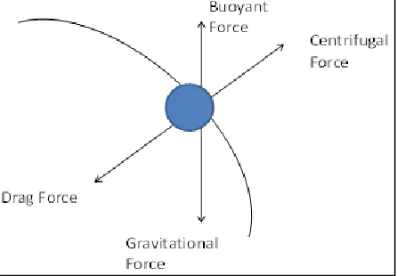
Fig. 1: Forces on Particles of Cyclone Separator
II. THEORY OF CYCLONE SEPARATOR
Most conventional way of designing a cyclone separator is by determining the cut of diameter of particle that needs to be separated. The basic principle of separation is the higher densities particles have higher inertia and they tend to rotate in larger radius. But, the heavier particles are rotating closed to the wall where they slipped down and removed from conical bottom. Low density particles rotate nearer the center and collected from the center of the cyclone.
(J4R/ Volume 04 / Issue 01 / 001)
better material which increase the manufacturing cost. At different microscale applications might not permit higher pressure drops.
A two phase particle-fluid system is essential for cyclone, in which particle transport equations and fluid mechanics can be used to define the behavior of a cyclone.
Vi: inlet velocity tangentially
r: rotational radius; cyclone's central axis,
Vt: tangential velocity
Vr: radial velocity component
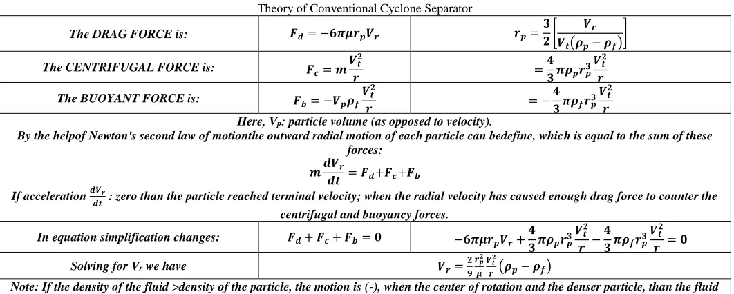
The particle is describing by buoyant, drag and centrifugal forces. Assume Stokes' law, the drag force is opposing the outward velocity on any particle in the inlet stream is:
Table – 1
Theory of Conventional Cyclone Separator
The DRAG FORCE is: 𝑭𝒅= −𝟔𝝅𝝁𝒓𝒑𝑽𝒓 𝒓𝒑=
𝟑 𝟐[
𝑽𝒓
𝑽𝒕(𝝆𝒑− 𝝆𝒇)
]
The CENTRIFUGAL FORCE is: 𝑭𝒄= 𝒎𝑽𝒕
𝟐
𝒓 =
𝟒 𝟑𝝅𝝆𝒑𝒓𝒑
𝟑𝑽𝒕𝟐
𝒓
The BUOYANT FORCE is: 𝑭𝒃= −𝑽𝒑𝝆𝒇𝑽𝒕
𝟐
𝒓 = −
𝟒 𝟑𝝅𝝆𝒇𝒓𝒑
𝟑𝑽𝒕 𝟐
𝒓
Here, Vp: particle volume (as opposed to velocity).
By the helpof Newton's second law of motionthe outward radial motion of each particle can bedefine, which is equal to the sum of these forces:
𝒎𝒅𝑽𝒓
𝒅𝒕 = 𝑭𝒅+𝑭𝒄+𝑭𝒃
If acceleration 𝒅𝑽𝒓
𝒅𝒕 : zero than the particle reached terminal velocity; when the radial velocity has caused enough drag force to counter the
centrifugal and buoyancy forces.
In equation simplification changes: 𝑭𝒅+ 𝑭𝒄+ 𝑭𝒃= 𝟎 −𝟔𝝅𝝁𝒓𝒑𝑽𝒓+
𝟒 𝟑𝝅𝝆𝒑𝒓𝒑
𝟑𝑽𝒕 𝟐
𝒓 − 𝟒 𝟑𝝅𝝆𝒇𝒓𝒑
𝟑𝑽𝒕 𝟐
𝒓 = 𝟎
Solving for Vr we have 𝑽𝒓=𝟐
𝟗 𝒓𝒑𝟐
𝝁 𝑽𝒕𝟐
𝒓 (𝝆𝒑− 𝝆𝒇)
Note: If the density of the fluid >density of the particle, the motion is (-), when the center of rotation and the denser particle, than the fluid motion is (+), away from the center.
III. MODEL USED FOR STUDY CYCLONE SEPARATOR
Fig. 2: Standard Cyclone Separator
Lapple Model
1) Lapple Model was developed based on force balance without considering the flow resistance. Lapple assumed that a particle entering the cyclone is evenly distributed across the inlet opening. The particle that travels from inlet half width to the wall in the cyclone is collected with 50% efficiency. The semi empirical relationship developed by Lapple to calculate a 50% cut diameter, dpc, is
𝑑𝑝50= [
9µ𝑊 2𝜋𝑁𝑒𝑉𝑔(𝜌𝑝)
]
1 2⁄
𝑁𝑒=Effective number of turns of the vortex (which ranges between 1 to 10);
𝑁𝑒≌
1 𝐻
[𝐿𝑏+ (𝐿𝑐|2)] 𝐻 𝐿𝑏=Length of body;
𝐿𝑐= Length of cone; H= height of inlet;
𝑉𝑔=Gas velocity (m/s) [which ranges between 6 to 24 m/s. usually it is taken as 18 m/s];
𝜌𝑝=particle density (kg/m3).
2) Shepherd and Lapple found empirically that pressure drop (expressed as the number of inlet velocity heads) depends inversely on exit diameter squared:
∆𝑃 =1 2
𝐾𝜌𝑔𝑉𝑔2𝐻𝑊 𝐷𝑒2
∆𝑃 = Pressure drop (Pa; N/m2); K= An empirical constant [Value: for a tangential inlet cyclone = 16 & for one with an inlet
vane= 7.5];
𝜌𝑝=particle density (kg/m3);
𝑉𝑔=Gas velocity (m/s) [which ranges between 6 to 24 m/s. usually it is taken as 18 m/s; W= Width of inlet; H= Height of inlet;
3) Lapple’s equation has been suits to an algebraic equation by Theodore and De Paola, which makes it more appropriate for compute applications:
𝜂𝑗= 1 [1 + (𝑑𝑝50⁄ ⁄𝑑𝑝𝑗)2] 𝑑𝑝50= Diameter of cut particle;
𝜂𝑗=Fractional efficiency in range j; 𝑑𝑝𝑗=Particle diameter in range j;
With the help of these equations we can determine effective collection efficiency and pressure drop for different inlet dimensions with fix range of velocity at different particle diameters.
IV. RESULT & DISCUSSION
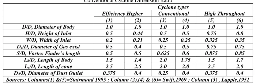
From the literature study standard cyclone dimensions ration was given below in table to be consider for assumption of cyclone design and to find out its collection efficiency with help of finding out pressure drop, too.
Table – 2
Conventional Cyclone Dimension Ratio Cyclone types
Efficiency Higher Conventional High Throughout
(1) (2) (3) (4) (5) (6)
D/D, Diameter of Body 1.0 1.0 1.0 1.0 1.0 1.0
H/D, Height of Inlet 0.5 0.44 0.5 0.5 0.75 0.8
W/D, Width of Inlet 0.2 0.21 0.25 0.25 0.325 0.35
De/D, Diameter of Gas exist 0.5 0.4 0.5 0.5 0.75 0.75
S/D, Vortex Finder’s length 0.5 0.5 0.625 0.6 0.875 0.85
Lb/D, Length of Body 1.5 1.4 2.0 1.75 1.5 1.7
Lc/D, Length of cone 2.5 2.5 2.0 2.0 2.5 2.0
Dd/D, Diameter of Dust Outlet 0.375 0.4 0.25 0.4 0.375 0.4
Sources: Columns(1) &(5)=Stairmand 1995 ; Column (2),(4) & (6)= Swift,1969 ; Column (3) , Lapple,1951 Source: Ref. A.10
From the used data of different literature review the collection efficiency had been find out using Lapple model for different sizes of particles.
Table – 3
Dimension Data of Cyclone Seperator
Dimensions Values Units
Entry area dimension H 0.80 m
W 0.96 m
Immersion tube dimensions S 2.26 m
De 1.50 m
Cylindrical part dimension LB 5.32 m
D 2.80 m
conical part Lc 3.18 m
discharge dia. Dd 0.55 m
Temperature at Cyclone inlet 800 oC
Pressure at Cyclone inlet -150 mmWg
density of material 1500 kg/m3
density of gases(NTP) 1320 kg/m3
(J4R/ Volume 04 / Issue 01 / 001)
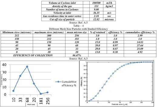
Volume at Cyclone inlet 100500 m3/h
density of the gas 331 kg/m3
Number of turns in Cyclones 9.00
Velocity at inlet 36.35 m/s
Gas residence time in outer vertex 2.18 sec
Cut off size of particle 12.82 microns
Source: Ref. A.5 Table – 4
Different Mesh Size Particles with Studied Efficiency
Minimum sieve (microns) maximum sieve (microns) mean micron size % of retained efficiency % cummulative efficiency %
212 300 256 3.0 1.0 2.99
150 212 181 1.0 1.0 1.0
90 150 120 15.0 0.99 14.83
45 90 68 39.0 0.97 37.64
20 45 33 29.0 0.87 25.09
0 20 10 13.0 0.38 4.92
EFFICIENCY OF COLLECTION 86.47%
Source: Ref. A.5
Fig. 3: Curve of Mesh Sizes vs Efficiency Fig. 4: Curve of Particles Size from 30µm- 10µm
Source: Ref. A.10
V. CONCLUSION
Effect of collection efficiency and pressure drop on the cyclone performance was studied using the developed Lapple Model. Decreasing the smaller particle size gives less numbers of efficiency of separation particles. It was concluded that for smaller size particle from the range 60 µm – 10µm very less collection efficiency achieved. The model prediction was in good agreement with Lapple model with study theoretical literature survey with other author’s findings which increases the creatibility of the method. For achieving good results between theoretical assumption and experimental data the Lapple theory and its containing parameter has good procedure to follow. In the Leith-Litch theory data was not match with the theoretical fractional efficiency curves. Leith-Licht and Barth theories worked better for staimand high-efficiency cyclone, but when dimensions changes due to gas flow patterns in the cyclone separator, and theoretical assumptions that work well for one design may not be valid for another. The theories need to be modified for a different range of cyclone designs and operating conditions.
ACKNOWLEDGMENT
The author would like to acknowledge technical SUPPORT FROM assistant prof.Ashish Parmar for his technical background support chemical engineering field.
REFERENCES
Papers
[1] Alves, A., Paiva, J., & Salcedo, R. (2015). Cyclone optimization including particle clustering. Powder Technology, 272, 14-22.
[2] Azadi, M., &Azadi, M. (2012). An analytical study of the effect of inlet velocity on the cyclone performance using mathematical models. Powder technology, 217, 121-127.
[4] Brar, L. S., Sharma, R. P., &Elsayed, K. (2015). The effect of the cyclone length on the performance of Stairmand high-efficiency cyclone. Powder Technology, 286, 668-677.
[5] de Souza, F. J., de Vasconcelos Salvo, R., & de Moro Martins, D. (2015). Simulation of the performance of small cyclone separators through the use of
Post Cyclones (PoC) and annular overflow ducts. Separation and Purification Technology, 142, 71-82.
[6] DeOtte Jr, R. E. (1990). A model for the prediction of the collection efficiency characteristics of a small, cylindrical aerosol sampling cyclone. Aerosol Science and Technology, 12(4), 1055-1066.
[7] Dirgo, J., & Leith, D. (1985). Cyclone collection efficiency: comparison of experimental results with theoretical predictions. Aerosol Science and Technology, 4(4), 401-415.
[8] Dirgo, J., & Leith, D. (1985). Cyclone collection efficiency: comparison of experimental results with theoretical predictions. Aerosol Science and Technology, 4(4), 401-415.
[9] Faulkner, W. B., & Shaw, B. W. (2006). Efficiency and pressure drop of cyclones across a range of inlet velocities. Applied engineering in
agriculture, 22(1), 155-161.
[10] Funk, P. A., Elsayed, K., Yeater, K. M., Holt, G. A., &Whitelock, D. P. (2015). Could cyclone performance improve with reduced inlet velocity?. Powder
technology, 280, 211-218.
[11] Gimbun, J., Chuah, T. G., Choong, T. S., &Fakhru'l-Razi, A. (2005). A CFD study on the prediction of cyclone collection efficiency. International Journal
for Computational Methods in Engineering Science and Mechanics, 6(3), 161-168.
[12] Gopani, N., & Bhargava, A. (2011). Design of high efficiency cyclone for tiny cement industry. International Journal of Environmental Science and Development, 2(5), 350.
[13] 13. Hamdy, O., Bassily, M. A., El-Batsh, H. M., &Mekhail, T. A. (2017). Numerical study of the effect of changing the cyclone cone length on the gas flow
field. Applied Mathematical Modelling, 46, 81-97.
[14] Iozia, D. L., & Leith, D. (1989). Effect of cyclone dimensions on gas flow pattern and collection efficiency. Aerosol Science and Technology, 10(3),
491-500.
[15] Iozia, D. L., & Leith, D. (1990). The logistic function and cyclone fractional efficiency. Aerosol Science and Technology, 12(3), 598-606.
[16] Jadhav, M. R. (2014). Design of cyclone and study of its performance parameters. International Journal of Mechanical Engineering and Robotics
Research, 3(4), 247. Jiang, Y., Qiu, G., & Wang, H. (2014). Modelling and experimental investigation of the full-loop gas–solid flow in a circulating fluidized bed with six cyclone separators. Chemical Engineering Science, 109, 85-97.
[17] Kang, Z., Yuan, Q., Zhao, L., Dai, Y., Sun, B., & Wang, T. (2017). Study of the performance, simplification and characteristics of SNCR de-NOx in
large-scale cyclone separator. Applied Thermal Engineering, 123, 635-645.
[18] Kaya, F., Karagoz, I., &Avci, A. (2011). Effects of surface roughness on the performance of tangential inlet cyclone separators. Aerosol science and technology, 45(8), 988-995.
[19] Mageshwaran, G., Raj, R. D., Joseph G, B., Jeevahan, J., Kuruvilla, K., & Francis, F. (2017). Computational Investigation of Flow Parameters and Efficiency of Single and Double Inlet Cyclone Separators. International Journal of Ambient Energy, (just-accepted), 1-8.
[20] Marinuc, M., &Rus, F. (2011). The effect of particle size and input velocity on cyclone separation process. Bulletin of the Transylvania University of Brasov, 4(53), 117-122.
Web Sites
[21] “Two Indians Die Every Minute Due To Air Pollution: Study”, accessed on 6
November,2016,http://indianexpress.com/article/india/two-indians-die-every-minute-due-to-air-pollution-study-4532450/.
[22] World DATA Atlas, 2015, https://knoema.com/atlas/India/topics/Environment/datasets,
Books
[23] DN Ghosh, S N Ghosh, In “Air and water Pollution Control Engineering”: New Central Book Agency, 1 Jan 2012, pp59-66
[24] L.K.Wang, N.C.Pereira, and Y.T.Hung, In “Handbook of environmental engineering”, Volume 1: Air Pollution Control Engineering, Humana Press, Inc.,