Development of Integrated SOL
/
Divertor Code and Simulation
Study in JAEA
Hisato KAWASHIMA, Katsuhiro SHIMIZU, Tomonori TAKIZUKA, Shinji SAKURAI,
Tomohide NAKANO, Nobuyuki ASAKURA and Takahisa OZEKI
Japan Atomic Energy Agency, Mukoyama, Naka 311-0193, Japan (Received 12 December 2005/Accepted 17 April 2006)
An integrated SOL/divertor code is being developed by the JAEA (Japan Atomic Energy Agency) for inter-pretation and prediction studies of the behavior of plasmas, neutrals, and impurities in the SOL/divertor region. A code system consists of the 2D fluid code for plasma (SOLDOR), the neutral Monte-Carlo code (NEUT2D), the impurity Monte-Carlo code (IMPMC), and the particle simulation code (PARASOL). The physical processes of neutrals and impurities are studied using the Monte Carlo (MC) code to accomplish highly accurate simulations. The so-called divertor code, SOLDOR/NEUT2D, has the following features: 1) a high-resolution oscillation-free scheme for solving fluid equations, 2) neutral transport calculation under the condition of fine meshes, 3) success-ful reduction of MC noise, and 4) optimization of the massive parallel computer. As a result, our code can obtain a steady state solution within 3∼4 hours even in the first run of a series of simulations, allowing the performance of an effective parameter survey. The simulation reproduces the X-point MARFE (multifaceted asymmetric ra-diation from edge) in the JT-60U. It is found that the chemically sputtered carbon at the dome causes rara-diation peaking near the X-point. The performance of divertor pumping in the JT-60U is evaluated based on particle bal-ances. In regard to the divertor design of the next tokamak of JT-60U, the simulation indicates the dependencies of pumping efficiency on the divertor geometry and operational conditions. The efficiency is determined by the balance between the incident and back-flow fluxes into and from the exhaust chamber.
c
2006 The Japan Society of Plasma Science and Nuclear Fusion Research
Keywords: SOL/divertor code, simulation study, Monte Carlo method, JT-60U, X-point MARFE, divertor pumping, pumping efficiency
DOI: 10.1585/pfr.1.031
1. Introduction
In order to predict the controllability of particles and heat in the divertor of tokamak reactors such as the ITER [1] and to optimize the divertor design, a comprehensive simulation by the integrated modeling taking into account various physical processes is indispensable. For the design study of the ITER divertor, modeling codes such as B2 [2], UEDGE [3], and EDGE2D [4] have been developed, and their results have contributed to the evolution of the divertor concept.
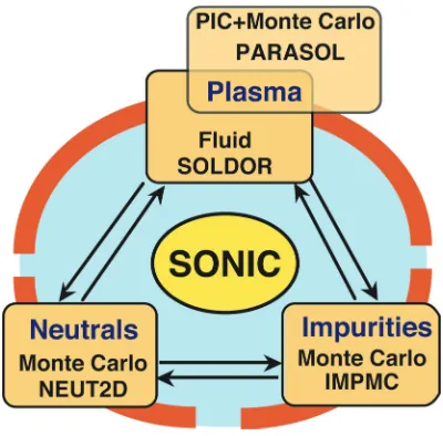
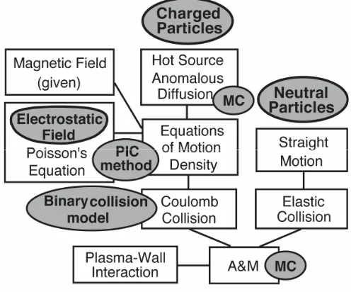
In the Japan Atomic Energy Agency (JAEA), diver-tor codes have also been developed for the interpretation and prediction of the behaviors of plasmas, neutrals, and impurities in the SOL/divertor regions. We have been de-veloping simulation codes originally, since physics mod-els can be verified quickly and with flexibility under the circumstance of close collaboration with the JT-60 exper-imental team. Figure 1 shows our code system, which consists of the 2-dimensional fluid code SOLDOR [5], the neutral Monte Carlo code NEUT2D [5], and the impurity Monte Carlo code IMPMC [6]. The particle simulation code PARASOL [7] has also been developed in order to es-tablish a physics modeling used in fluid simulations, such
author’s e-mail: [email protected]
as the boundary condition at the divertor target and heat transport along the field line.
A combination of the SOLDOR and NEUT2D was
Fig. 1 Development of SOL/divertor codes and integration in the JAEA.
c
completed. The features of this code are as follows: fine meshes near the divertor plates, complex divertor config-urations including a pumping chamber, reduction of the Monte-Carlo noise in the neutral transport calculation, etc. An integration of the SOLDOR, NEUT2D, and IMPMC codes is being carried out as a way to self-consistently simulate the SOL/divertor plasmas in the present tokamaks and in future devices. This integrated code is called the “SONIC” code.
In this paper, we describe the present status of SOL/divertor codes developed by the JAEA. A simulation study has been carried out for the JT-60U experiments [8,9] and for designing the divertor [10] of the next tokamak of JT-60U, National Centralized Tokamak (NCT)∗), which is a modification program of the JT-60U to establish high beta steady-state operation [11]. We present the recent results of simulations of the X-point MARFE (multifaceted asym-metric radiation from edge) and divertor pumping in the JT-60U experiments. The particle controllability according to the divertor geometry (the width of exhaust slot) and the operational condition (the strike point position) is demon-strated for the NCT.
2. SOL
/
Divertor Codes in JAEA
In this section, the characteristics and present status of the SOL/divertor codes, SOLDOR, NEUT2D, IMPMC, and PARASOL, are presented.
2.1
SOLDOR code
The SOLDOR code is a 2D multi-fluid modeling for plasmas. The model equations are identical to the original B2-code [12], as follows:
∂ρa
∂t +
∆ ·ρ
av//ab
+ ∆ ·ρav⊥a
= Sρa , (1)
∂ ∂t
ρ
av//a
+ ∆ ·ρ
av//a2+Pa
b + ∆ ·ρav//av⊥a
+
Zana
ne
b· ∆ (Pe) − Pa ∆ ·b
+ ∆ ·Π//a
=
b
Rfricab + Ra∆ T·b + SPa//, (2)
∂ ∂t a 3 2naTi+
1 2ρav
2 //a + ∆ · a 3 2naTi+
1 2ρav
2
//a+Pa
v//ab
+ ∆ ·
a
3 2naTi+
1 2ρav
2
//a+Pa
v⊥a
+ ∆ ·
a
v//aΠ//a
+ ∆ ·
a
qa
=−v//eb · ∆ Pe − neνeq(Ti−Te) + Wi, (3)
∗)
The JT-60U modification is renamed from NCT to JT-60SA (Super Advanced) at present.
∂ ∂t
3 2neTe
+ ∆ ·
3
2neTe+Pe
v//eb
+ ∆ ·
3
2neTe+Pe
v⊥e + ∆ ·qe
= +v//eb· ∆ Pe + neνeq(Ti−Te) + We, (4)
where the suffix of “a” denotes the ion species,bis the unit vector along the magnetic field line,ρa = mana is mass
density, v//a is parallel velocity, v⊥a = −D⊥a/na· ∇⊥na
is cross field anomalous velocity, Ti is ion temperature,
andTeis electron temperature. The viscosity termΠ//a =
−η//a∇//v//a −η⊥a∇⊥v//a, the ion and electron heat
con-ductionqi/e =−κ//i/e∇//Ti/e−κ⊥i/e∇⊥Ti/e, the equi-partition
neνeq(Ti−Te), the friction force with b-speciesRfricab, and
the thermal forceR∇T
a are included in the model equations.
The termb· ∇Pain the momentum equation is converted
intob·∇Pa=∇·(bPa)−Pa∇·b, and the termv//eb·∇Pein the
energy equations represents the energy related to the elec-tric field. The transport along the field line is assumed to be classical. The boundary condition at the divertor plates is as follows:
v//i=Cs≡
Ti+Te
mi
1/2
, (5)
Qi=γiTiniv//i+
1 2miv
2
//iniv//i, (6)
Qe=γeTenev//e, (7)
whereQi, Qeare the parallel heat flux densities andγi, γe
are the heat transmission factors (γi = 2.5 andγe = 4.0
[12]). These conditions will be improved to the accurate ones on the basis of the PARASOL simulation results, as discussed in Sec. 2.4.
The diffusion coefficients across the field, such as D⊥a, η⊥a, κ⊥i = niχ⊥i, κ⊥e = neχ⊥e, are assumed to be
anomalous and spatially constant. The terms of the right-hand side, Sρa, Spa//, are sources of mass and the mo-mentum of a-species, while Wi, We are sources of ion
and electron energy, respectively. These source terms arise from the interactions with neutral particles. Therefore, the plasma transport and the neutral transport must be solved consistently.
In order to solve the system of the above equations, we must address five difficult requirements. Here we briefly describe our measures to solve these problems as features of the SOLDOR code.
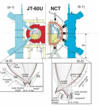
* Complex divertor structure
Fig. 2 (a-1), (b-1) ; the schematic cross sections of the JT-60U and the NCT. (a-2), (b-2) ; their mesh structures for the SOLDOR/NEUT2D simulations.
* Strong nonlinearity of equations
Non-linear equations are linearized by the Newton-Raphson method in order that physical terms can be eas-ily included or modified to extend the code. Not only the steady state solution but also the time evolution of the plasma parameters can be investigated using this code. * Two-dimensional problem
The finite difference equations are solved using the approximate factorization (AF) method, where a two-dimensional system is split into two one-two-dimensional sys-tems in the poloidal and radial directions. The AF method obtains the solution in two steps at every time step. The equations in each step can be solved efficiently, because they are a block tridiagonal system. The code can be ex-tended to three dimensions straightforwardly.
* Numerical stability for convective terms
Numerical treatment of the convective terms, such as ∇·ρav//ab
, ∇·ρav2//a+Pa
b, is generally very difficult to perform. An inadequate scheme results in a solution con-taining numerical oscillation. We apply the total
variation-diminishing (TVD) scheme [13] for the convective terms. This scheme adds the minimum dissipation according to need as a method to obtain a solution without numerical oscillation. It can simulate even a shock wave without de-forming the shock front. Therefore, the TVD scheme is the most familiar one in computational fluid dynamics. * Couple with Monte-Carlo code
In some divertor codes, the fluid equation is used for the neutral transport as well as for plasma ions. However, the neutral transport must be solved using a Monte-Carlo code in order to analyze the experimental data in detail or to perform a design study. The MC calculation requires a relatively large amount of computational time and its re-sult contains a degree of MC noise, which deteriorates the convergence toward a steady state solution. This matter is described in Sec. 2.2.
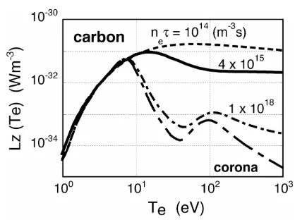
dis-Fig. 3 Carbon radiation coefficient for the simplified non-corona model.
cussed later in Sec. 2.3. A simple radiation model is em-ployed in which a fraction of carbon impurity is assumed to be a fixed value, typically 1∼2% of the deuterium density, and the radiation loss is evaluated byWr = −nenzLz(Te).
The radiation loss rateLz(Te) is enhanced by the impurity
recycling effect, assumingneτrecycle =4×10¹⁵s m−3[14],
as shown in Fig. 3.
2.2
NEUT2D code
The NEUT2D code calculates the neutral density (n0)
and the source terms (Sρa, Spa//, Wi, We). We explain the
Monte-Carlo techniques used in the code as an example of tracking a D atom. The neutral particles move at a constant velocity until a collisions takes place. The collision point is determined from the relation of
L
0
ds/λtot(s) = −lnξ, (8)
whereLis the free flight length,λtot(s) the local mean free
path,sthe distance from the previous collision point along a straight line, andξa uniform random number. The local mean free path of atomλtot(s) is summed over ionization
by electrons (I-e), charge exchange (CX), and elastic colli-sions (EL a) as follows:
1/λtot(s)=1/λion+1/λCX+1/λEL a. (9)
When a collision occurs, the collision type, CX or EL a, is chosen in accordance with its probability. The weight, corresponding to test flight neutral flux, is reduced by ion-ization [15];
wnew=wold·
1/λCX+1/λEL a
1/λion+1/λCX+1/λEL a .
(10) This technique, called “suppression of absorption”, effec-tively reduces the variance. The tracking of a test parti-cle is continued after selecting a new velocity according to either a CX or EL a collision. The track-length estima-tor method is used as the scoring method to calculate the
Table 1 Collision processes between neutral and plasma particles in the NEUT2D code.
atom
I e e+D → e+D++e
CX D++D → D+D+
EL a D++D → D++D
molecular
I e e+D2 → e+D+2 +e
DS e+D2 → e+D+D
DS e+D2 → e+D++D+e
EL m D++D2 → D++D2
ion
DS e+D+2 → e+D++D DS e+D+2 → e+D++D++e
DS e+D+2 → D+D
RC e+D+ → D
neutral density and source terms. Neutral moleculues are also traced with the same technique. The collision between neutral and plasma particles included in the NEUT2D code is listed in Table 1. As for the molecular ions D+2, a disso-ciation process is assumed to occur immediately after an ionization event in a molecule. The mean free path of this dissociation process in the poloidal plane is less than 1 mm and can be neglected.
The features of the NEUT2D code are as follows. * Region to trace neutral particle
To accurately evaluate the particle balance in the system, the neutral particle transport is solved inside the whole vessel: the core region (r/a ≤ 1.0), the SOL/divertor, and the vacuum region including the exhaust structure. In other divertor codes, generally the neutral par-ticles are assumed to be absorbed at the core edge and the complicated structure of the exhaust system is simplified. * Fine mesh near divertor plates
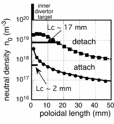
Figure 4 shows a typical variation of neutral density along the poloidal direction in JT-60U simulations. The characteristic lengthLcchanges from∼2 mm in attached
plasma to∼2 cm in detached plasma. The mesh size near the plates must be around 2 mm as shown in Fig. 2 in order to simulate the transition between attached and detached conditions. The reduction of mesh size below 1 cm was generally difficult since the MC noise increased signifi-cantly with a decrease of the mesh size.
* MC noise reduction
We have succeeded in reducing the MC noise by intro-ducing a newly developed “piling” method (averaging the Monte Carlo result in time) [as described in the appendix]. This method enables us to use the fine mesh.
* Particle balance
Fig. 4 Neutral density profiles along the poloidal length from the inner divertor target at attached and detached plasmas. The spatial resolutions of the calculation need to be below the characteristic lengthLc=n0(dn0/dr)−1of∼2 mm.
in each iteration step of the SOLDOR code (refer to the use of the Newton-Raphson method). Convergence to steady state is assured by this careful treatment of the particle bal-ance between the SOLDOR and NEUT2D codes.
* Optimization on parallel computer
We have optimized the NEUT2D code performance by using Message Passing Interface (MPI) on the massive parallel computer, SGI ALTIX 3900. As a result, a steady state solution can be obtained within a short computational time of 3∼4 hours even in the first run of a series of simu-lation studies, which is about 10 times faster than the con-ventional divertor codes coupled with the MC code. Thus our code enables effective parameter survey.
The SOLDOR and NEUT2D codes have been suc-cessfully combined and used in experimental analysis and divertor design. We adopt a model that calculates energy and momentum source terms arising from the atomic and molecular reactions in the DEGAS code [16]. The plasma boundary in SOLDOR is set atr/a=0.95. The profiles forne(r),Te(r) and Ti(r) inr/a < 0.95 in the NEUT2D
calculations are specified with each function. For exam-ple, the density profile has a function ofne(r) = (ne0−
neb)· 1−(r/0.95a)2
m
+neb, wherenebis the density at the
boundary (r/a =0.95) calculated in the SOLDOR, andm is fixed at 0.3∼0.5. Total power and particle fluxes (Qtotal,
Γion) across ther/a =0.95 surface are given as the input
parameters. The recycling of deuterium is assumed to be 100% at the first wall. The treatment of the interaction with walls is the same as that in the DEGAS code. The pumping speed is specified by an albedo for neutrals in front of the exhaust port or cryopanel. Under these conditions, the neu-tral transport and the plasma transport in the divertor/SOL region including the core edge (r/a ≥0.95) are simulated self-consistently.
Fig. 5 Illustrations of various processes treated in the IMPMC code.
2.3
IMPMC code
Simulation codes for impurity transport are classified basically into fluid codes and Monte Carlo codes. In most 2D multi-fluid divertor codes [2–4], impurity transport is solved simultaneously as a fluid species. On the other hand, some elaborate Monte Carlo codes have been devel-oped for the interpretation of impurity behavior in the di-vertor, e.g., DIVIMP [17] and IMPMC [6]. In these Monte Carlo codes, impurity transport is solved under the back-ground plasma parameters obtained by a simple divertor code named the “Onion-Skin model” [18], in order to take full advantage of the available experimental data.
We regard the Monte Carlo modeling for impurity transport as superior to fluid modeling in regard to kinetic effects and the modeling of impurity generation and in-teractions between impurities and walls. The neglect of the thermalization process for impurity ions, i.e., an as-sumption ofTimp =Tiused in fluid model, is actually
in-valid for impurities with low charge states near the divertor plates [19]. The kinetic effects alter the thermal force. The direction of the thermal force on impurity ions having a high velocity (the order of thermal velocity of plasma ions) is opposite that of the fluid approximation [20, 21]. The dissociation processes of methane, which are very compli-cated [22, 23], are impossible to treat using fluid modeling. For impurity transport, therefore, the IMPMC code has been developed based on Monte Carlo techniques [24]. This model includes (1) impurity generation due to phys-ical and chemphys-ical sputtering, (2) ionization of sputtered neutrals and the dissociation processes of methane, (3) par-allel motion of impurity ions along field lines, (4) Coulomb scattering, (5) cross-field diffusion, and (6) atomic pro-cesses (ionization and recombination), as shown in Fig. 5.
The features of the IMPMC code are as follows. • Impurity transport is simulated in realistic divertor
ge-ometry; accordingly, comparison with experimental data can be accomplished in detail.
• Diffusion processes in velocity space for Coulomb scattering are simulated using a Monte Carlo method, simultaneously taking into consideration the parallel motion of impurity ions.
• The dynamics of methane (CD4) are simulated.
Methane is generated by chemical sputtering on the assumption of the yield YCD4 = 0.05 [25]. All the
dissociation processes (CD+3,CD3,CD+2, etc) are
in-cluded in the MC modeling.
Detailed modeling for methane proved that hydrocar-bons chemically sputtered from the private wall by neu-tral particles plays important roles in carbon contamination near the X-point in high density divertor plasma [23, 26].
A conventional MC algorithm for the diffusion pro-cess in velocity space has a disadvantage in that the impu-rity ions must be traced with a time step shorter than the slowing down time (∆tτs). The first version of IMPMC
code demands a huge amount of computational time in the case of detached plasma because of this extremely short slowing down time, typically, τs ∼ 4 ×10⁻⁹ s for C3+.
Thus, we have developed a new diffusion model to resolve this defect in the Monte-Carlo code.
The impurity ions are diffused in the velocity space by Coulomb collisions with the plasma ions, resulting in diffusion along the magnetic field line in real space. The IMPMC code correctly treats the velocity-space diffusion (VD model) for this process. The DIVIMP code has pre-viously employed the spatial diffusion model (SD model), where this process was simulated by adding random dis-placement of∆s= 2D//∆t·rGat every step. Here,sis
the parallel position,D//=v2
thτsis the parallel diffusion
co-efficient, andrGis the normal random number. Comparing
these two models, we pointed out that the SD model can-not be applied for plasma in which the characteristic time of parallel motion is comparable to collision time [27]. The SD model in the DIVIMP code was replaced with the VD model at need [28].
We have reformulated these processes, i.e., the rela-tion between the velocity and spatial diffusion processes. These processes are described by the Langevin equations,
sn+1 =sn+vn//∆t,
vn+1
// =vn//−(vn//−Vf)∆t/τs
(11) +F//∆t/mz+{<∆v//2>∆t}1/2rG,
where the indexn is the time step number,< ∆v2
// > ∆t
is the mean square deviation of parallel velocity change during a time step∆t, andVf is the plasma flow velocity.
We are developing a new algorithm to simulate this paral-lel diffusion process with a time step much larger thanτs.
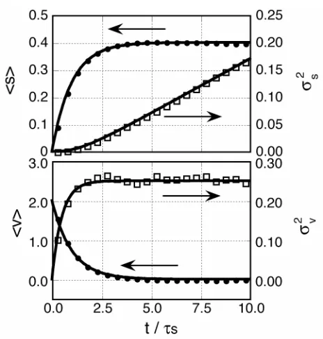
Details of the new diffusion model will be published else-where [29]. The means and the standard deviations of the parallel positionsand the parallel velocityv//in the simu-lation obtained by the VD model are denoted by symbols in Fig. 6. We used the parameters ofs(t=0)=0, v//(t=0)=
Fig. 6 The means and the standard deviations (σ2) of the par-allel position (s) and the parallel velocity (v//) in the new diffusion model (solid line) and the VD model (symbols).
2,Vf =0,F// =0,∆v//2∆t=0.025,τs =0.2,∆t=0.01,
andN(number of test particles)=5000. Results of model simulations (symbols) agree well with analytical solutions of Langevin equations (solid lines). Then the position of the test particle at any time can be chosen from the normal distribution with means and standard deviationσ2
S
ob-tained from the analytical solution. The parallel velocity is also chosen from the normal distribution with meanvand standard deviationσ2
v. This model neglects the correlation
between space and velocity in the early phase (tτs). It
should be noted that the distribution at any time, not only t τsbut alsot ≤τs, can be determined as far as
impu-rity ions stay in the region where the plasma parameters are considered to be nearly constant. In the case where the par-allel transit time is comparable to the slowing down time, i.e., attached plasma, the VD model should be employed for this diffusion process.
The cpu time can be significantly reduced by this new algorithm. In a case where 5000 test particles were traced during 1 msec in the typical detached divertor plasma (ne ∼ 1×10²⁰ m−3, Te ∼ 1 eV, see Fig. 8), the
conven-tional method (∆t = (1/20)τs) took 1 hour whereas new
algorithm (∆t=10−6s) took only 12 sec.
2.4
PARASOL code
Analyses of divertor experiments in present devices and predictions of divertor performance in future reac-tors have been carried out by using comprehensive simula-tion codes with the fluid model, such as the B2, UEDGE, EDGE2D, and SOLDOR codes. In the fluid model for SOL/divertor plasmas, however, various physics models are introduced, i.e., boundary conditions at the plasma-wall boundary, heat conductivity, viscosity and so on. A kinetic approach is required to examine the validity of such physics models, and to improve/develop accurate physics models. One of the most powerful kinetic models is parti-cle simulation. In order to satisfy the above-mentioned re-quirement, we have been developing a particle simulation code called PARASOL (PARticle Advanced simulation for SOL and divertor plasmas). There are various versions of the PARASOL code: 1D (one-dimensional) PARA-SOL, 2D (two-dimensional) slab PARAPARA-SOL, 2D separa-trix PARASOL, etc. Details of the simulation model of PARASOL have been described in Ref. 7. Figure 7 shows a frame sketch of the PARASOL code. The outline of each part is briefly presented below.
This model is fundamentally a time-dependent elec-trostatic particle-in-cell (PIC) model. The elecelec-trostatic po-tential, including the sheath potential at the plasma-wall boundary, is self-consistently calculated using Poisson’s equation. Although the system sizeLis very much larger than the Debye lengthλDin real plasmas, PARASOL
sim-ulations with the grid size∆of the order ofλDare available
to study such plasmas with smaller values ofL/λD=102∼
103. This is because the characteristics of SOL/divertor
plasmas are almost unchanged by changingL/λDexcept
for the sheath region. The simulation domain is bounded by walls. A magnetic configuration is given and part of (or
Fig. 7 Frame sketch of the PARASOL code.
all) field lines intersects the walls. The 1D PARASOL sys-tem is bounded by two divertor plates, while the 2D PARA-SOL system is surrounded by walls. This system treats charged particles and neutral particles. Ion orbits are fully traced in this given magnetic field and the electrostatic field is calculated self-consistently, while guiding-center orbits are followed for electrons.
The effect of drift in SOL/divertor plasmas is fully simulated by the PARASOL code. The full-orbit calcu-lation provides a complete description of the ion polariza-tion drift, which is essential for magnetic pre-sheath for-mation in the magnetic field intersecting a divertor plate obliquely [30, 31]. The E× B drift influences the SOL flow speed as well as the flow speed at the plasma-wall boundary [31, 32]. TheE ×B drift in the magnetic pre-sheath is a key factor for 2D pre-sheath formation, which has not been considered in fluid simulations. Analytic forms of the boundary conditions applicable to the fluid code have been established on the basis of PARASOL simulations. These new conditions, instead of the simple ones described in Sec. 2.1, will be incorporated into the SOLDOR code af-ter the code is improved to treat drift flows.
Anomalous transport across the magnetic field lines is simulated using a Monte Carlo technique. A spatial dis-placement perpendicular to the magnetic field is added ran-domly for every time step after the ordinary motion.
The deformation of the velocity distribution func-tion from the Maxwellian affects the sheath characteris-tics. This deformation is essential for the heat transport parallel to the magnetic field line in SOL/divertor plas-mas. Coulomb collisions, therefore, play a very important role in SOL/divertor plasmas. The collisional diffusion in the velocity space is the main mechanism to supply high-energy electrons. These electrons can escape to the diver-tor plate, while low energy electrons are trapped in a SOL plasma by the sheath potential. The PARASOL code em-ploys a Monte-Carlo binary collision model [33]. At every time step a particle in a cell suffers binary Coulomb colli-sions with an ion and an electron, which are chosen ran-domly in the same cell. The change in the relative velocity due to binary collisions is added after computing the col-lisionless motion. Total momentum and total energy are conserved intrinsically.
neu-tral particles simultaneously with those of charged parti-cles. We optionally simulate the effects of neutrals on the basis of simplified models instead of treating neutral par-ticles directly. The characteristic lengthLAM related to
atomic and molecular processes is usually much smaller than the whole system sizeL. When we study the physics including such shorter characteristic length, we set the PARASOL system carefully so thatL LAM ∆. It
is not necessary to set these values as the same as those of realistic SOL/divertor plasmas. The purpose of PARASOL simulation is to study the basic physics.
Plasma control methods are easily introduced into PARASOL simulations. Divertor biasing is simply given by the wall boundary condition in Poisson’s equation. The effects of biasing on the SOL flow were investigated us-ing 2D PARASOL simulation. The asymmetry of the SOL flow can be controlled by the biasing [32].
Thus, establishment of physics modeling in the PARASOL code is progressing. Through the development of our code system described in Fig. 1, we aim to verify the physics models used in the fluid code SOLDOR on the basis of the PARASOL simulation.
3. Recent Simulation Results
Efforts towards the integration of the SOLDOR, NEUT2D, and IMPMC codes are being made. The SOL-DOR and NEUT2D codes have been successfully com-bined and improved to speedily obtain a steady state solu-tion as a result of the success in the reducsolu-tion of MC noise and optimization on the parallel computer. The IMPMC code has been improved, i.e., the calculation efficiency in the detached plasma has been significantly increased with the new diffusion model. Simulations using these codes have been performed for analyses of the JT-60U divertor experiments and for study of the NCT divertor design.
3.1
Analysis of X-point MARFE in the
JT-60U
Detached divertor by strong gas puffing has been stud-ied as a way to reduce the heat load on the divertor tar-get. However, in discharges with such divertor plasmas, radiation near the X-point is enhanced locally and of-ten leads to a MARFE (multifaceted asymmetric radia-tion from edge). The main plasma is cooled directly due to the deterioration of the impurity shielding effect, and the energy confinement is then degraded. In order to un-derstand the physical process in a MARFE, JT-60U de-tached divertor plasmas with X-point MARFE are simu-lated using the SOLDOR/NEUT2D code with employing the simplified non-corona radiation model. The simulation is carried out for the JT-60U at an equilibrium ofIp/BT=
1.5 MA/3.0 T in the lower single null divertor configura-tion. The total power fluxQtotal =2 MW and the particle
outflux ofΓion =0.2×10²²s−1 are used under the
exper-imental conditions. We assume a particle diffusion coeffi
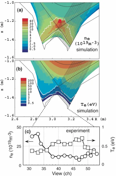
-Fig. 8 Contour plots of the calculated electron density (a) and temperature (b) in the divertor region at a simulation of the JT-60U X-point MARFE by the SOLDOR/NEUT2D code. The regions ofne=10-20 (1019m−3) and ofTe= 0.5-1 (eV) are bounded by white lines. (c) Density and tem-perature profiles obtained by the spectroscopic measure-ment along the viewing lines (set of solid lines in (a) and (b)).
cientD⊥ = 0.3 m2/s and a thermal diffusivity of electron and ionχe⊥ = χi⊥ = 1 m2/s. Those transport coefficients have been chosen based on the evaluations of various toka-maks [36]. The convective transport perpendicular to the magnetic field is not taken into account at present. The re-cycling coefficients at the divertor plates and walls are set to 1.0 for ion and neutral particles. The fraction of carbon impurity to ion density is assumed to be 1%.
Figures 8 (a) and (b) show the contour plots of the calculated electron density and temperature. The X-point MARFE with peaked density ne ∼ 4 ×10²⁰ m−3 arises
with introducing the strong gas puffing of 0.8×10²²s−1.
profiles obtained by the spectroscopic measurement along the viewing lines (solid lines in Figs. 8 (a) and (b)) for the JT-60U experiment [37]. The measurement is carried out using the Stark broadening and assuming the Boltz-mann distribution in the volume recombination plasmas [38]. Approaching the X-point, the density further in-creases up to 4×10²⁰m−3 and the electron temperature
decreases to 0.5∼1 eV. It is found that the calculated den-sity and temperature profiles fairly agree with those of the experiment.
The characteristics of the X-point MARFE can be qualitatively reproduced by the present code. In order to study the quantitative characteristics, further simulation analyses will be carried out using the integrated SONIC code, which contains the elaborated Monte Carlo impurity code.
In regard to radiation, the bolometer measurement in-dicated that the peaked value reached several MW/m3[39].
Using the plasma profile calculated as shown in Fig. 8, the impurity transport is investigated using the IMPMC code. This code includes the modeling of the dissociation pro-cess of methane and the dynamics of dissociation products (CD+3, CD3, CD+2, etc). For simplicity, these complicated
dissociation processes of CD4are not taken into account in
the present calculations. Instead, we treat chemically sput-tered CD4as a carbon C with a low energy (∼1 eV). Figure
9 shows the ionization points of carbon chemically sput-tered from the divertor targets and the dome under attached and detached conditions, respectively. The chemical sput-tering yield is set toYCD4 =0.05. For the attached case,
the carbon is ionized near the divertor target and most ions return to the target due to the friction force. In contrast, the carbon atom can penetrate the X-point for the detached case as shown in Fig. 9. After the pre-calculation of the ionization process, the IMPMC simulation is performed in which the transport and atomic processes including the charge exchange recombination are traced. The radiation power near the X-point reaches 3∼4 MW/m3, which is
Fig. 9 Simulations of carbon impurity transport at attached con-dition (open circle) and detached concon-dition with the X-point MARFE (closed circle) by the IMPMC code.
sistent with the experimental result. It is found that the radiation is brought dominantly by the deep penetration of neutral carbons sputtered from the private dome and the di-vertor targets. This outflux of carbon in the simulation cor-responds to that of methane chemically sputtered by neu-tral particles.
Thus, a high accuracy analysis of the X-point MARFE is performed using the divertor code, taking advantage of the fine mesh and MC modeling.
3.2
Simulation of divertor pumping in the
JT-60U
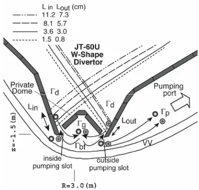
Divertor pumping is a key issue for particle control in the steady state high beta operation of future tokamak devices. In order to extrapolate the divertor pumping char-acteristics from the present experimental data, a simula-tion of divertor pumping in the JT-60U is carried out using the SOLDOR/NEUT2D code, whose results are compared with the experimental results [40].
To investigate the effect of the equilibrium config-uration on divertor pumping, the strike positions were changed in the simulations as shown in Fig. 10. The pa-rameters of Ip/BT = 1.5 MA/3.5 T, Qtotal = 5 ∼ 7 MW,
Γion=0.1×10²²s−1,D⊥=0.3 m2/s, andχe⊥=χi⊥=1 m2/s
are used under the experimental conditions with NBI heat-ing. With these fluxes and diffusion coefficients, the
lation reproduces the experimental divertor plasmas fairly well. The fraction of carbon impurity to ion density is as-sumed to be 2%. The pumping is performed using only the inside pumping (IP) slot and both-side pumping (BP) slots with a fixed pumping speedSpump = 40 m3/s in front of
the pumping port. The exhaust chamber through below the private dome to the outer pumping port is not changed for both cases; namely, it is not divided into an inner and an outer side even in the BP case. The neutral fluxes around the divertor are analyzed to clarify the pumping character-istics. The fluxes are classified asΓd(the generated flux at
the divertor targets),Γg(the flux into the exhaust chamber
through the slot),Γbf(the back-flow flux from the exhaust
chamber to the plasma side), andΓp(the pumping flux), as
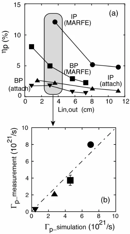
shown in Fig. 10. The pumping efficiencyηp[≡Γp/Γd] is
Fig. 11 (a) Pumping efficiencyηp (≡Γp /Γd) obtained by the simulations as a function of Lin for IP (inside pump-ing) and of Lout for BP (both-side pumping) based on the experiments. Symbols correspond to the cases of IP with MARFE (•), BP with MARFE (), and IP () and BP ()at attached conditions. (b) Comparisons of the pumping fluxΓp between measurement and simulation atLin∼Lout∼3 cm.
compared among those conditions. In both attached cases, the gas pufffluxΓpuffis fixed to 1×10²¹m3/s. In the both
MARFE cases, it is changed to 8∼25×1021m3/s along the experiments because the MARFE generation is restricted depending on the strike point position and the gas puffflux. The results in Fig. 11 (a) show that 1)ηpdecreases with an
increase of (Lin,Lout), 2)ηpat IP becomes larger than that
at BP within a factor of three, and 3)ηpis enlarged
remark-ably under the MARFE conditions. Comparison ofΓpwith
measurement and simulation atLin∼Lout∼3 cm is shown
in Fig. 11 (b). TheΓpuffin the simulation is adjusted to that
in the measurement data. These values show fairly close agreement together with the above dependencies on IP, BP, and the attached and detached conditions.
Analyzing these properties based on the particle bal-ances, item 2) can be explained in term of the balance of
Γp =Γg−Γbf. As indicated by the simulations, they can
be induced separately. A comparison of the IP and BP cases shows a decrease of the pumping flux fractionΓp/
Γg(=1−Γbf/Γg) by a factor of 0.7 in the BP case,
indi-cating an increment of the back-flow fluxΓbfthrough the
two slots for BP. The fraction ofΓp/Γgis nearly constant,
independent of the attached and detached conditions. En-hancement of the pumping efficiency under the detached MARFE condition in item 3) is caused by an increase of the incident flux fractionΓg/Γd by a factor of 2∼3 since
the ionization front moves away from the divertor target and the fraction of ionized neutrals is significantly reduced. The item 1) in which theηpdepends on the divertor
geom-etry will be discussed later in the next section.
Thus, the simulations for divertor pumping in the JT-60 U substantially reproduce the experimental results and provide a means to understand the pumping characteristics. Based on these results, control of the particles by divertor pumping is investigated in the next section, which focuses on the design study of the NCT divertor.
3.3
Particle controllability by divertor
pump-ing in the NCT
In order to optimize the divertor design in the NCT (National Centralized Tokamak) where the heat and parti-cle flux density in the divertor are considerably higher than those in the JT-60U, the heat load on the divertor targets, pumping capability, and geometric effect have been inves-tigated using the SOLDOR/NEUT2D code [10].
A semi-closed divertor with the vertical target at an incidence angle of 45◦with respect to the poloidal flux sur-face was proposed as part of the first conceptual design of the NCT. Cryopanels for inner and outer divertor pumping (Spump ≤ 200 m3/s each) are positioned under the private
dome and outer divertor target, separately, based on the simulation results in Sec. 3.2; higher pumping efficiency is obtained by use of one exhaust slot in each pumping sys-tem such as that of the IP case.
slot (din, dout) and the strike point position (Lin, Lout) in
Fig. 12 (a) on divertor pumping since divertor pumping be-comes a crucial issue for particle control under the high recycling conditions expected in NCT operation. For the simulation,Qtotal is fixed to 12 MW (80% of input power
at steady-state operation) andΓion =1×10²² s−1 is used,
since this particle flux can be anticipated in the high re-cycling condition in JT-60U-size devices. Such high recy-cling condition is feasible by gas puffing or pellet injection. The fraction of carbon impurity to ion density is assumed to be 1%. A parameter survey is carried out regarding the slot widths of three cases and the strike positions of four
Fig. 12 (a) Schematic view of the NCT divertor when (din,dout) and (Lin, Lout) are changed to evaluate the dependences of pumping efficiency on them. (din,dout) are the width of exhaust slot between the private dome wing and the inner or outer divertor target, and changed by extend-ing the dome wextend-ing. (Lin,Lout) are the distance from the dome wing extension point on the target to the strike point of separatrix similar to previous JT-60U analyses, and changed by sweeping the X-point. (b) Definition of the slot view angleθin. Neutral fluxes (Γd,Γg,ΓbfandΓp) are defined in the same manner as those in Fig. 10.
cases, taking advantage of our code, i.e., its speedy calcu-lation and flexibility.
The effect of the exhaust slot width (din,dout) is
evalu-ated in cases of 20, 10, and 5 cm. The strike point position is fixed toLin = 3 cm andLout = 4.1 cm. The pumping
speed is fixed at 100 m3/s on each cryopanel. The pump-ing efficiency is increased by narrowpump-ing the slot as shown in the hatched regions of Fig. 13. These features are also clarified by analyzing the neutral flux at the positions of the divertor target, exhaust slot, and cryopanel as shown in Fig. 12 (b), in a way similar to the previous JT-60U anal-yses. The generated flux of neutralsΓdoriginates mainly
around the strike point on the divertor target with veloc-ity in a nearly perpendicular direction in relation to the di-vertor target, with the main parts of those neutrals passing through the slot due to the vertical inclination of the di-vertor target. In such a condition, the back-flow fraction
Γbf/Γgis reduced from 0.9 in the case of 20 cm in width
to 0.8 in the case of 5 cm in width, while the pumping flux is increased. Consequently, the pumping efficiency (ηp≡Γp/Γd) for the 5 cm case is enlarged at a factor of∼3
in comparison with the 20 cm case.
The effect of strike point position is evaluated by changing the (Lin, Lout) in cases of a ∼ d as shown in
Fig. 12 (a). Figure 13 shows the dependence of the pump-ing efficiency on the (Lin,Lout) in three cases of (din,dout).
The maximum pumping efficiency is obtained at a narrow width ofdin = dout = 5 cm at a position near the private
dome (Lin = 3 cm, Lout = 4.1 cm) as mentioned above.
However, it decreases steeply with an increase ofLin and
Lout. This is led by a reduction of the incident fraction
Γg/Γd with a decrease in the slot view angle θin as seen
in Fig. 12 (b). As the slot width is increased, this depen-dent relationship is weakened by the balance between an increase of the back-flow fractionΓbf/Γgand an increase
ofΓg/Γd with largerθin. Typically, ηp at a slot width of
20 cm does not depend on theLin andLout,however, effi
ciency is lowest in three cases due to a largeΓbf/Γg.
Rel-atively higher efficiency in wide regions ofLinandLoutis
sustained at a slot widthdin=dout=10 cm.
These results indicate that the pumping efficiency is determined by balances of the incident and back-flow fluxes, depending on the divertor geometry and operational conditions. Further optimization of those two factors will be pursued in consideration of particle controllability and the flexibility of plasma shaping.
4. Summary
Integration of the SOL/divertor simulation codes of SOLDOR, NEUT2D, IMPMC and PARASOL is being de-veloped by the JAEA for interpretation and prediction stud-ies of SOL/divertor plasmas. Through the development of this code system, we aim to verify the physics mod-els used in the fluid code on the basis of the PARASOL simulation. The physical processes of neutrals and im-purities are treated by the Monte Carlo (MC) code to ac-complish highly accurate simulations. The combined code with SOLDOR and NEUT2D has the following features: 1) a high-resolution oscillation-free scheme, TVD, applied using the finite-difference method of fluid equations, 2) neutral transport calculation under the complex divertor configurations including the pumping chamber with fine meshes (≤2 mm) near the divertor targets, 3) successful reduction of MC noise, and 4) optimization of MC calcu-lation using the massive parallel computer. As a result, our code can obtain a steady state solution within 3∼4 hours, performing an effective parameter survey.
A simulation of the detached plasmas of the JT-60U reproduces the X-point MARFE well. It shows that the peaked radiation near the X-point is induced by the deep penetration of carbon impurities generated by chemical sputtering. The performance of divertor pumping in the JT-60U is evaluated based on particle balances. Cases of inside pumping (IP) and both-sides pumping (BP) for the attached/detached plasmas are investigated. Their
9 10 1 2 3 4 5 6 7 8 9 10 1 2 3 1 2 3 4 5 6 7 8 9 10 11 12 13 14 15 16 17 18 19 20 21 22 23 Sa @ @ @ @ @ @ @ @ @ @ @ @ @ @ @ @ @ @ @ @ @ @ @
S = Sa
(a) Single averageing method
clear
1 2 3 4 5 6 7 8 9 10 11 12 13 14 15 16 17 18 19 20 21 22 23 Sa @ @ @ @ @ @ @ @
Sb @ @ @ @
@ @ @ @
Sc @ @ @ @ @ @ @
S = Sa+Sb+Sc 9 10 11 12 9 10 11 12 9 10 11 12 9 10 11
(b) New piling method
clear
Fig. A1 Averaging methods of Monte-Carlo results. The sequential numbers denote the Monte-Carlo calcula-tion cycle and the symbol (@) denotes the variable stored for the Monte-Carlo calculacalcula-tion at each time step. Each scoring variable is cleared at the timing indicated by an arrow. The variation of total scoring (S) in piling method is much smaller than that in the single averaging method.
formance can be characterized by the pumping efficiency
ηp[≡(Γp; pumping flux)/(Γd; generated neutral flux at the
target)]. We find that the degradation ofηpin the BP case
is due to the increase of back-flow flux through the two exhaust slots. For NCT divertor design, the dependence ofηp on the width of the exhaust slot and the strike point
position is studied. The maximumηp can be obtained
us-ing a narrow slot of 5 cm among the 3 studied cases of 5, 10 and 20 cm at strike point positions ofLin = 3 cm
andLout=4.1 cm. This is achieved by a significant
reduc-tion of the back-flow flux from the exhaust chamber. Leav-ing away the strike point from the exhaust slots, theηpis
decreased by the reduction of incident flux. Further op-timization of geometry and operational conditions are the subjects of future research, taking particle controllability and the flexibility of plasma shaping into consideration.
The SOL/divertor codes developed by the JAEA are useful for interpreting the experimental results of the JT-60U as well as providing guidelines for future NCT diver-tor design.
Acknowledgements
The authors are grateful to the members of the JT-60 team and the NCT facility design team for their support and useful advice. They wish acknowledge Drs. H. Ni-nomiya, M. Kuriyama, M. Kikuchi, and N. Hosogane for their encouragement. This work is partly supported by a Grant-in-Aid for Scientific Research of Japan Society for the Promotion of Science.
Appendix. Piling Method
×(Msets)×(6 sources)×(104meshes)×(10 variables).
To reduce this large memory size, we introduced a pil-ing method, which requires only three sets of scorpil-ing vari-ables. The three sets (Sa,Sb,Sc) are provided and the lat-est calculation result is stored in a set selected from among Sa,Sb, andScas shown in Fig. A1 (b). This figure shows an example of the case ofM = 12 groups. The scoring variables are cleared in some time sequence denoted by arrows. Source terms in the SOLDOR code are calculated using the total scoringS =S a+S b+S c. In this procedure, they are averaged from the last 9 (=2(M/3)+1) groups to the last 12 (= 3(M/3)) groups. In the averaging method with a single set of scoring variables (Fig. A1 (a)), the re-duction factor of the MC noise significantly changes from 1 to 1/√M. In contrast, the factor in the piling method is flattened, i.e., 1/√2(M/3)+1 ∼1/√M. This property in MC calculation using the piling method improves the convergence to a steady state.
[1] G. Janeschitzet al., J. Nucl. Mater.290-293, 1 (2001). [2] R. Schneideret al., J. Nucl. Mater.196-198,810 (1992). [3] T.D. Rognlienet al., J. Nucl. Mater.196-198,347 (1992). [4] R. Simoniniet al., J. Nucl. Mater.196-198,369 (1992). [5] K. Shimizuet al., J. Nucl. Mater.313-316,1277 (2003). [6] K. Shimizuet al., J. Nucl. Mater.220-222,410 (1995). [7] T. Takizuka, M. Hosokawa and K. Shimizu, Trans. Fusion
Tech.39,111 (2001).
[8] S. Ide and the JT-60 team, Nucl. Fusion45, S48 (2005). [9] A. Isayama and the JT-60 team, Phys. Plasmas12,056117
(2005).
[10] H. Kawashimaet al., Fusion Eng. Des.81, 1613 (2006). [11] H. Tamaiet al.,Proc. 20th IAEA Fusion Energy Conf.
(Vil-amoura, 2004) FT/P7-8, and references therein.
[12] B. Braams, A multi-fluid code for simulation of the edge plasma in tokamaks, NET rep. EUR-FU IXII-80-87-68, Comm. of the European Communities (1987).
[13] S.R. Chacravarthy and S. Osher, A new class of high ac-curacy TVD schemes for hyperbolic conservation laws, AIAA paper 85-0363 (1985).
[14] D.E. Post, J. Nucl. Mater.220-222,143 (1995). [15] M. Hughes and D. Post, J. Comput. Phys.28,43 (1978). [16] D.B. Heifetzet al., J. Comp. Phys.46, 309 (1982); D.B.
Heifetz,Physics of Plasma-Wall Interactions in Controlled Fusion(D.E.Post and R.Behrisch, Eds., Plenum Press, New York and London, 1986) p.695.
[17] P.C. Stangeby and J.D. Elder, J. Nucl. Mater.196-198,258 (1992).
[18] K. Shimizuet al., J. Nucl. Mater.196-198,476 (1992). [19] K. Shimizuet al., J. Nucl. Mater.241-243,167 (1997). [20] D. Reiseret al., Nucl. Fusion38,165 (1998).
[21] K. Shimizu and T. Takizuka,Proc. 27th EPS on Controlled Fusion and Plasma Physics, (Budapest, Hungary), P4. 094 (2000).
[22] A.B. Ehrhardt and W.D. Langer, Princeton Plasma Physics Laboratory Report, PPPL-2477 (1987).
[23] K. Shimizuet al., Plasma Physics and Controlled Nuclear Fusion Research 1994 (Proc. 15th Int. Conf. Seville, 1994), Vol.3, IAEA, Vienna, 431 (1996).
[24] K. Shimizu and T. Takizuka, J. Plasma Fusion Res.71,801 (1995).
[25] J. Rothet al., Atomic and Plasma-Material Interaction Data for Fusion (Supplement to the journal Nuclear Fusion) Vol. 1, 63 (1991); J.V. Philipset al., J. Nucl. Mater.313-316, 354 (2003).
[26] S. Higashijimaet al., J. Nucl. Mater.266-269,1078 (1999). [27] K. Shimizu and T. Takizuka, ”Impurity transport code based on Monte Carlo techniques (IMPMC) ”, Tech. Mtg on ITER Divertor Physics Design, Garching, 1994. [28] P.C. Stangeby and J.D. Elder, Nucl. Fusion 35, 1391
(1995).
[29] K. Shimizuet al.,submitted toJ. Nucl. Mater. [30] R. Chodura, Phys. Fluids25,1628 (1982).
[31] T. Takizuka and M. Hosokawa, Contrib. Plasma. Phys.40, 471 (2000).
[32] T. Takizuka, M. Hosokawa and K. Shimizu, J. Nucl. Mater. 313-316,1331 (2003).
[33] T. Takizuka and H. Abe, J. Comput. Phys.25,205 (1977). [34] A. Bergmann, Nucl. Fusion42, 1162 (2002).
[35] T. Takizuka and M. Hosokawa,to be published inContrib. Plasma Phys. (2006).
[36] ITER Physics Basis, Nucl. Fusion39,2391 (1999). [37] T. Nakano,Proc. 4thFusion Energy Association Meeting
of AESJ and JSPF, 1A032 (2002).
[38] T. Fujimoto, Plasma Spectroscopy, ch.4 (Clarendon Press Oxford, 2004).