(Received 5 August 2019/Accepted 12 November 2019)
This paper describes an emergency fast discharge scheme of toroidal field (TF) coils of fusion demo reactors for reduction of induced voltage applied to turn insulations of conductors. TF coils are divided into serially connected segments that are electrically isolated from each other and only the coil segment having a failed coil is rapidly discharged. It was found from a circuit current analysis that this discharge scheme enables to reduce the insulation voltage with a factor of ~0.6 or less and which would contribute to ensure reliability of the turn insulations.
c
2019 The Japan Society of Plasma Science and Nuclear Fusion Research
Keywords: nuclear fusion, toroidal field coil, quench, first discharge, turn insulation voltage, fusion demo reactor DOI: 10.1585/pfr.14.1405167
1. Introduction
In emergency conditions of toroidal field (TF) coils of nuclear fusion devices, such as quench of super-conductors, they must immediately discharge their current to suppress conductor temperature rising due Joule heating of copper stabilizers contained in strands.
In the case of ITER, the TF coil circuit consists of 9 cells connected in series with one power supply, where each cell has a pair of TF coils and a fast discharge unit (FDU) for the emergency shutdown [1]. The fast discharge of coils, however, generates a high induced voltage, which is applied to turn insulations. This voltage is proportional to the TF coil self-inductance for a given discharge time constant.
The ITER TF-coil set is operated with the conductor current of 68 kA and has the self-inductance of 17.3 H, the number of turns of 134×18=2,412, and the total initial FDU resistance of 9×97 mΩ∼0.9Ω[1,2]. These numerical values give the initial discharge time constant of 19 s. The turn-to-turn voltage is then calculated to be 26 V that gives the maximum insulation voltage between the radial plate and the conductor of 286 V [3].
The TF coil size of a fusion demo reactor called “JA DEMO”, conceptually designed by the Joint Special De-sign Team for Fusion DEMO [4, 5], is about 1.4 times greater than ITER, which gives a 3 times greater self-inductance if the conductor current and the magnetic field strength are the same magnitudes as those of ITER and then generates a 3 times turn-insulation voltage that is quite capable of losing reliability of TF coils.
author’s e-mail: [email protected]
Because the self-inductance is proportional to a square of the number of turns, the increase in the conductor cur-rent is one of means for reducing the turn insulation volt-age and is tried in the recent TF coil design of JA DEMO, where the conductor current is raised from 68 kA specified in the ITER TF coil design to 83 kA. The increasing in the discharge time constant also reduces the insulation voltage, which is however restricted because it causes the conduc-tor temperature rise beyond its acceptable level in the coil quench event [6].
In this paper, we will present a fast discharge scheme of the TF coil current to reduce the insulation voltage with-out the increase in its time constant, dividing a set of TF coils into multi segments that are electrically isolated from each other.
2. Fast Discharge Scheme
2.1
Induced insulation voltage
The turn to turn voltagevT T generated in the fast
dis-charge of the TF coils is defined by
vT T =L0IOP/(NTτd)=IOPR0/NT, (1)
where L0 is the TF coil self-inductance, IOP the
operat-ing coil current,NT the total number of turns, andτd the
discharge time constant (= L0/R0withR0 being the total discharge resistance). The total number of turns is given byNT =nCNC, whereNC is the number of TF coils and
nC the number of turns per coil. The conductor is wound
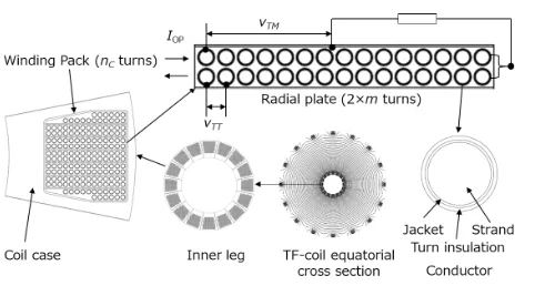
in a double pancake along grooves of a radial plate (RP) with 2mturns. As in the ITER design [3], the RP is con-nected (through a resistor) to the conductor cross-over at
c
2019 The Japan Society of Plasma
Fig. 1 Definitions of turn to turn voltagevT T and maximum in-sulation voltagevT M=2mvT T.
Table 1 Design parameters of TF coils for ITER and JA DEMO.
the plate edge (see Fig. 1) so that their potentials are equal-ized. Then the maximum turn insulation voltagevT M is
given bymvT T, which is applied between the RP and the
conductor jacket.
Table 1 presents design parameters of TF coils, which shows that the insulation voltage of JA DEMO is about three times greater than that of ITER for the same dis-charge time constantτd.
To reduce the maximum insulation voltage vT M, we
suppose to divide TF coils intoMC segments, where coils
of the numberi = MC(j−1)+k, (j = 1,· · ·,NC/MC,
k = 1,· · ·,MC), which belongs to thek-th segment, are
serially connected and electrically isolated from coils with the differentk(see Fig. 2). In this case, each coil segment is individually required to have a power supply.
Then, only the coil set having a failed coil, which is termed in the following as “failed set”, is to be rapidly dis-charged. We also define the term “intact set” as the coil set in normal operating condition.
For example, whenMC =2, one is a set of odd
num-ber coils and the other of even ones. In this case, the number of turnsNT is a half of the non-segmented coil
set and the self-inductanceLof the divided set of TF coils becomes a quarter of the non-segmented set becauseLis roughly proportional to the square of the number of turns,
Fig. 2 Multi-segmentation of 16 TF coils, which are divided into (a) 2 segments (Two-divided TF coil sets) and (b) 4 seg-ments (Four-divided TF coil sets), where numbersiof in-side are of coils and thosekof outside of coil segments.
Table 2 Values of self and mutual inductances ¯Mi,jbetweeni-th and j-th TF coils of JA Demo (i,j=1 - 16, see Fig. 2).
i.e.,L∼L0/MC2. We therefore expect the turn to turn
volt-agevT T to be halved according to Eq. (1).
The current of intact set, however, is magnetically coupled with that of the failed set, i.e., the intact set ab-sorbs the magnetic flux of failed set losing its current, and increases beyond its acceptable level. Therefore, it is nec-essary to control the intact set current appropriately in this coil discharge scheme. To do this, we analyze time evolu-tions of the intact and failed set currents.
2.2
Two-divided TF coil sets
Coil currents Ii, (i =1, · · ·, MC) are calculated for
MC=2 by using circuit equations
˙
I1+ξ1I˙2+λ1I1=0 and ˙I2+ξ2I˙1+λ2I2 =0, (2) withξ1 = M12/L1,ξ2 = M21/L2,λ1 = R1/L1, andλ2 =
R2/L2, whereRis the resistance,Lthe self-inductance,M the mutual inductance, and the subscript 1 denotes quanti-ties of the failed coil set and 2 of the intact one.
Appendix A presents equations for calculating self and mutual inductances of divided coil segments with those of the non-segmented set of TF coils. ForMC =2,
we haveL1 =L2=13.05 H andM1,2=M2,1 =8.94 H us-ing mutual inductance values for JA DEMO presented in Table 2.
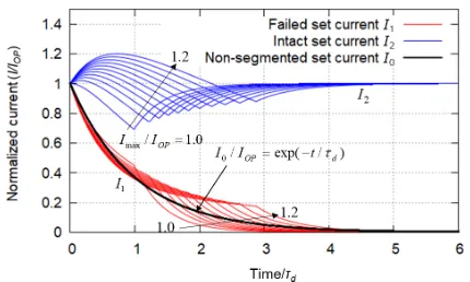
Figure 3 shows typical time evolutions of coil currents
I1 and I2 to explain the scheme of fast discharge for the two-divided TF coil set, where the currentI0 of the non-segmented coil set is also shown for comparison, which is decayed with a time constant ofτd, and all currents are
Fig. 3 Typical time evolutions of currents in fast discharge scheme of two-divided TF coil set, where the intact set is re-short-circuited (R2=0) att=τRso that it can rapidly absorb the magnetic flux released from the failed set.
fast discharge.
When we choose resistance values under the condition ofR1being sufficiently larger thanR2, the failed set current
I1is more rapidly and monotonically decayed, whereas the intact set currentI2 initially increases with absorbing the magnetic flux released from the failed set and then start to decay after taking its maximum valueImax (> IOP).
Fur-thermore,I2increases again att=τR, when the resistance
R2 is removed from the intact set circuit, i.e., re-short-circuited, and asymptotically reaches a certain value that depends onτR.
Circuit parameters R1, R2, and τR for this discharge
scheme are determined by the following conditions for givenτdandImax/IOPwith time functions of currents,I1(t) andI2(t) (see Appendix B):
(a)0∞I2
1(t)/IOP2 dt=
∞
0 I 2
0(t)/IOP2 dt=τd/2
(b)I2(t)|t→∞/IOP=1
(c) max(I2(t))=Imax
⎫⎪⎪ ⎪⎪⎪⎪⎬ ⎪⎪⎪⎪⎪ ⎪⎭.
(3)
The first condition (a) makes the effective decay time constant of the failed set current be that of the non-segmented TF coil set,τd, to roughly equalize their
ther-mal impacts. The second one (b) is for the intact set to ab-sorb the magnetic flux released from the failed set within their acceptable upper current limit to decay the currentI1 as fast as possible. For the third condition (c), the allow-able valueImaxof the currentI2should be determined from viewpoints of stresses generated in coil structures and sta-bility of superconductors.
Resistance ratios R1/R0 andR2/R0 calculated under conditions of Eq. (3) are presented in Fig. 4 as functions of
Imax/IOP, whereR0 (=L0/τd) is the resistance of the
non-segmented TF coil set. Figure 4 also shows the insulation voltage reduction factorχ, whereχis given by the ratio of the turn-to-turn voltagevT T to that of the non-segmented
TF coil set (vT T0), i.e.,
Fig. 4 Resistance ratiosR1/R0andR2/R0, and insulation voltage
reduction factorχforMC=2.
Fig. 5 Time evolutions of coil currents normalized byIOP for MC =2 withImax/IOPas a parameter, where calculation parametersR1,R2, andτRwere determined by Eq. (3) (see Figs. 3 and 4).
χ=vT T/vT T0=
IopR1/(NT/MC)
/(IopR0/NT)
=MCR1/R0 with MC=2.
Resulting time evolutions of normalized coil currents
I1/IOP and I2/IOP are shown in Fig. 5 with Imax/IOP as
a parameter. In this figure, the current increment ΔI2 =
Imax−IOPis proportional to the flux consumed andΔI2 =
IOP−I2(τR) to that stored by the intact set. We roughly
see (ΔI2+ ΔI2)/IOP~const. (~0.3) in Fig. 5, which is
pro-portional to the total flux released by the failed set and ab-sorbed by the intact set. The largeΔI2orImax/IOPcan thus
reduce the required resistanceR1(∝χ) of the failed set for consuming its own flux, especially in the early stage of the discharge. The reduction factorχis then decreased from 0.69 to 0.52 in the range of 1≤ Imax/IOP ≤1.2 as shown
in Fig. 4.
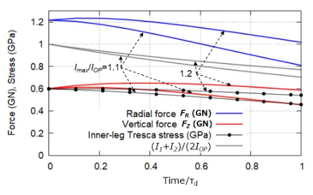
It would be necessary to estimate impacts of the tran-sient overcurrent of the intact set on the TF coil struc-tural integrity because it increases magnetic forces. The magnetic field generated by TF coils gives them the hoop force, which is expressed by the radial forceFR and the
vertical forceFZ. Figure 6 shows their time evolutions for
Fig. 6 Time evolutions of magnetic forces acting on TF coils and Tresca stress generated in inner-leg structures for Mc=2.
Fig. 7 Time evolutions of maximum field strengthBmaxon con-ductor axis and corresponding minimum current sharing temperatureTCS forMC=2.
rapidly decreasing, the increase in the local toroidal mag-netic field during the overcurrent transient is not so much asI2. Although appreciable increase is seen in the vertical forceFZfor Imax/Iop =1.2, it causes little increase in
re-sulting stresses acting on inner-leg structures, as shown in Fig. 6.
We also estimated the decrease in the current sharing temperatureTCS[6] during the overcurrent transient ofI2.
The current sharing temperature gives an index of upper temperature limit to keep the stability of super-conductors, at which the superconductor is in transition from super-conducting state to normal one and the conductor cur-rent is shared by both the superconducting and normal-conducting (copper) strands.
Figure 7 shows time evolutions of maximum magnetic field strength Bmax on the conductor axis and the corre-sponding minimum current sharing temperatureTCS, the
latter of which is designed to be ~6 K for the TF coil con-ductor of JA DEMO. We see from Fig. 7 that the increase inBmaxis small and thereforeTCS is hardly decreased for
Imax/Iop≤1.2.
Furthermore, we should pay attention to overturning forces acting on TF coils. These forces are generated by poloidal magnetic field that interacts with TF coil currents
Fig. 8 Time evolutions of coil currents normalized byIOP for MC=4 withImax/IOPas a parameter, whereI1is of failed
set to be rapidly discharged.
to cause toroidal forces in opposite directions across the TF coil equatorial plane. Since overturning forces are directly proportional to TF coil currents and (I1(t)+I2(t))/(2IOP)≤
1 at least forImax/Iop≤1.2, (see Fig. 6), net torques acting
on inter-coil structures between coils of intact and failed sets are always small in comparison to those in the normal operation.
From these consideration using JA DEMO TF coil pa-rameters, affects of the transient overcurrent of I2 would be acceptable at least for Imax/Iop ≤ 1.2, which
corre-sponds to the safe reduction factorχ≥0.52. If we choose
Imax/Iop > 1.2, the peak magnetic field appreciably
be-comes greater than that in the normal operating condi-tion as predicted from Bmax curves drawn in Fig. 7, (e.g.
Bmax → 14.3 T for Imax/Iop = 1.3), and the increase in
the stress and the decrease inTCS would not be ignored in
considerations of the TF coil integrity and stability.
2.3
Four-divided TF coil sets
It is expected that the increase in the number MC of
coil segments reduces the insulation voltage more effec-tively because the rough estimation similar to Eq. (1) gives vT T ∝1/MC. Figure 2 (b) shows coil segment numbers for
MC =4. In this case, we need to calculate four coil
cur-rentsIk, (k=1 - 4), whereI1is the current of the failed coil set with the resistance ofR1and currentsIkwithk=2 - 4
are for intact sets that are given the same discharge resis-tanceR2. Note thatI2 =I4because of geometrical symme-try in the positional relationship of coils withk=2 and 4 (see Fig. 2 (b)).
We solved circuit equations for these currents numer-ically withIk(0) = IOP, (k = 1 - 4), and their results are
shown in Fig. 8. In this case, intact sets were not re-short-circuited because the magnetic flux released from one failed coil set can easily be shared and consumed by residual three intact coil sets. Therefore intact set currents
I2,I3, andI4in Fig. 8 are not re-increased, unlike Fig. 5 for
MC=2.
Fig. 9 Resistance ratios R1/R0 and R2/R0, and the reduction
factorχ forMC = 4 (without re-short-circuit) as func-tions ofImax/IOP. The lower value ofχis obtained for Imax/IOP>1.01 in comparison toMC=2.
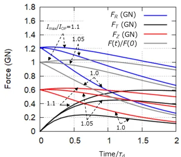
Fig. 10 Time evolutions of magnetic forcesFR,FT, andFZ act-ing on TF coils with segment number of 2 or 4, where F(t)=(F2
R(t)+F
2
T(t)+F
2
Z(t))
1/2.
insulation voltage reduction factorχ=4R1/R0, where we see thatχis always lower than that ofMC =2 except for
Imax/IOP<1.01. This result makes us have a high
expecta-tion forMC=4 to obtain a smaller value ofχeven without
the re-short-circuiting.
Figure 10 shows magnetic forces acting on TF coils that belong to the coil segment with the numberkof 2 or 4, of which current takes a peak value as shown in Fig. 7. There is no problem in the hoop force (radial and vertical forces) forImax/IOP ≤1.1. However, the toroidal force is
generated in intact coil segments with the numberkof 2 and 4. This reason is that only the current of failed coil segment withk =1 is decreased more rapidly than those of intact ones as seen from Fig. 8. Figure 11 shows the distribution of the toroidal force per unit length of TF coils withk=2 and 4.
In Fig. 11, the attractive force f3,2 generated between coil currentsI2andI3or f4,3, betweenI3andI4is greater than f2,1 betweenI1 andI2 or f1,4betweenI4 andI1.
Re-Fig. 11 Distribution of toroidal component of magnetic force (arb. unit) per unit length generated by fast discharge withMC =4 andImax/IOP =1, where fi,j, (i, j =1 -4) is the magnetic attractive force betweeni-th and j-th coil currents andFT k= fk+1,k−fk,k−1is the net toroidal
force acting onk-th coil.
sultantly, the net toroidal forcesFT2andFT4are generated on coils ofk = 2 and 4, respectively, unlike the case of
MC = 2 that generates the same attractive force between
adjacent coils. On the other hand, no toroidal force is gen-erated on coils ofk=1 and 3 because of the geometrical symmetry that givesf4,3= f3,2and f2,1= f1,4.
We see from Fig. 10 that the toroidal force FT
be-comes the same order of magnitude as the hoop force (FR,
FZ) acting on TF coils att∼τd. This force would generate
additional stresses in the coil case and the RP except for
k=1, especially near the inner leg (see Fig. 11).
For example, the toroidal forceFT becomes ~400 MN
att ∼0.5τd for Imax/IOP =1.1 with the radial and
verti-cal forces (FR andFZ) being still nearly the same values
as those of the normal operation. Then, we roughly esti-mate the additional toroidal stress generated in the RP to be several tens MPa, using the current center line length of the TF coil~50 m, the coil width~1.6 m, and the RP metal occupation factor ~0.15. This additional stress would be intolerable for the coil design.
Here we define a force vector (FR,FT,FR) acting on
the coil mass center. IfdF(t)/dt≤0 withF(t)=(F2
R(t)+
F2
T(t)+FZ2(t))1/2 (see Fig. 10) can be used as a condition
for keeping the stress within its designed value, we roughly estimate the acceptable range as 1≤Imax/IOP ≤1.05 that
gives the minimum reduction factorχ∼0.55.
It should be noted that this toroidal force generation makes the re-short-circuiting be unacceptable forMC=4,
because final values of currents becomeI1 = 0 and Ik =
IOP, (k=2 - 4), which gaveF(t→ ∞)=1.13F(0).
2.4
Discussions
Two fast discharge schemes of multi-segmented TF coils have been considered withMC=2 and 4.
The discharge scheme withMC =4 decays the failed
Comprehensively the discharge scheme would prefer to selectMC=2 rather thanMC =4 for achieving a lower
reduction factor of the insulation voltage.
3. Summary
An emergency fast discharge scheme of TF coils for fusion demo reactors has been considered to reduce in-duced voltage applied to turn insulations. In this scheme, TF coils are divided into multiple segments that are indi-vidually connected serially and electrically isolated from each other.
Each coil segment has a pair of discharge resistorsR1 andR2 withR1 >R2. In an emergency condition, the coil segment having a failed coil is serially connected toR1and other segments (intact sets) toR2and thus only the coil seg-ment that includes a failed coil is discharged more rapidly. The intact set then has a role of absorbing the mag-netic flux released from the failed set and therefore its cur-rents is initially increased. To enhance this action and de-cay the failed set current more rapidly, the resistorR2 con-nected to the intact set is removes again (re-short circuit-ing) at an appropriate timing in the case of the two-divided coil set (MC=2).
It was found from the circuit current analysis for JA DEMO TF coil parameters that the insulation voltage can be reduced by the factorχ of 0.6 or less (minimum 0.52 forMC = 2) within the transient overcurrent of the intact
set being tolerable level.
The four-divided set (MC = 4) seems to reduce the
factorχ more effectively. However, this scheme has no advantage compared to the case forMC=2 because of the
toroidal force generation that causes additional stresses in coil structures and thus prevents the decrease inχ.
Acknowledgments
This work was conducted in the framework of the Joint Special Design Team for Fusion DEMO collabora-tion program with Nacollabora-tional Institutes for Quantum and Ra-diological Science and Technology, Japan.
[1] ITER Design Description Document, DDD 11, Magnet, 8.
[6] ITER Design Description Document, DDD 11, Magnets, 7. Conductors, ITER_D_2NBKXY v1.2 (2009).
Appendix A. Inductances of Divided
Coil Set
The self-inductance and the mutual inductance in Eq. (2) are calculated for MC = 2 by L1 = L2 = M∗1,1 (=M∗2,2),M1,2=M2,1=M∗1,2(=M2,1∗ ), where
Mi∗,j(=M∗j,i)=(NC/MC) NC/MC
k=1 ¯
Mi,MC(k−1)+j,
with ¯Mi,j (= M¯j,i), (i,j = 1,· · · ,NC), being mutual
in-ductances of the non-segmented set of TF coils, values of which are presented in Table 2.
Appendix B. Solutions of Circuit
Equations
Solutions of circuit equations Eq. (2) forMC=2 with
initial conditions ofI1(0) = I2(0) = IOP are obtained for
t≤τRto be
I1/IOP=γ12e−α1t−γ22e−α2tand
I2/IOP=γ11e−α1t−γ21e−α2t,
whereαi=X
1−(−1)i(1−Y)1/2 and γi j=2−1
(1−Zj)(1−Y)−1/2−(−1)i
with
X= λ1+λ2
2(1−ξ2), Y=
4λ1λ2(1−ξ2) (λ1+λ2)2
,
andZj=
2λj(1+ξ)
(λ1+λ2) , (i,j=1,2 andξ=ξ1=ξ2).
Fort > τR, coil currents are calculated from circuit
equations Eq. (2) withλ2=R2/L2=0 by
I1(t)=I1(τR) exp
−λ1(t−τR)/
1−ξ2 and