Studies on Accelerator-Driven System in JAEA
∗
)
Toshinobu SASA and Hiroyuki OIGAWA
J-PARC Center, Japan Atomic Energy Agency, Ibaraki 319-1195, Japan
(Received 31 May 2013/Accepted 30 May 2014)
After the Fukushima nuclear accident, reduction of radioactive wastes got much attention. To reduce the burden of radiological nuclides contained in spent nuclear fuel, Partitioning-Transmutation (P-T) technology is noted at the discussion of the national fuel cycle policy. By using P-T technology, radiological hazard can be reduced less than 1/100. As for the system for effective transmutation, an accelerator-driven system is desirable as a dedicated transmutor. To perform basic studies for accelerator-driven system, Japan Atomic Energy Agency has promoted design of the Transmutation Experimental Facility (TEF) within the framework of the J-PARC project. A lead-bismuth spallation target, which is bombarded with 400 MeV - 250 kW protons, and a low-power subcritical reactor will be installed in the facility. We will start construction within few years after a national review of TEF.
c
2014 The Japan Society of Plasma Science and Nuclear Fusion Research
Keywords: accelerator-driven system, partitioning, transmutation, J-PARC, radiological waste, minor actinide, Transmutation Experimental Facility
DOI: 10.1585/pfr.9.4401113
1. Inroduction
Due to the Great East Japan Earthquake and ensuing tsunami, the Fukushima-Daiichi Nuclear Power Plant has been seriously damaged and many nearby residents are still forced to be evacuated. The cabinet of Japan decided to re-duce the dependency on nuclear power generation. The Science Council of Japan suggested prioritizing research and developments (R&Ds) to reduce the radiological bur-den of high level wastes (HLW).
Japan Atomic Energy Agency (JAEA) precedes R&Ds to reduce the radiological hazard of HLWs by Par-titioning and Transmutation (P-T) technology [1]. As for the transmutation of radiological waste, the accelerator-driven system (ADS), which combines a high intensity proton accelerator and a fast subcritical core, is discussed from a viewpoint of transmutation efficiency and compat-ibiliy from a power generation cycle. Within the frame-work of the J-PARC project, JAEA is preparing to con-struct the Transmutation Experimental Facility (TEF) to study the minor actinide (MA) transmutation by both MA-loaded fast reactors and ADS [2]. TEF is located at the end of LINAC, which is also important components to be de-veloped for future ADS, and shares the proton beam with other experimental facilities in J-PARC. R&Ds for impor-tant technologies required to build the TEF are also per-formed, such as application methods of MA bearing fuel in the critical/subcritical assembly, spallation product re-moval method especially for the polonium, and so on. The objectives and construction schedule of the TEF, the latest design concept, and key technologies to construct TEF are
author’s e-mail: [email protected]
∗)This article is based on the presentation at the Conference on Laser and Accelerator Neutron Source and Applications (LANSA ’13).
described.
2. JAEA Proposed ADS
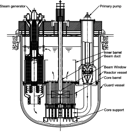
JAEA’s reference design of ADS is a tank-type sub-critical reactor, where lead-bismuth eutectic (LBE) alloy is used as both the primary coolant and the spallation target, as shown in Fig. 1. The spallation target region is located at a central part of the core. In the target region, LBE is flow-ing from the core bottom along to the dedicated wrapper tube and flow guide. A proton beam with about 1.5 GeV -30 MW proton beam is supplied from the accelerator to
Fig. 1 ADS for transmutation of MA proposed by JAEA.
c
operate the ADS. The rated power, which is controlled by adjusting the injected proton beam current of the accelera-tor, is 800 MWth.
A tank-type system is adopted to eliminate the neces-sity of heavy primary piping. All primary components, including two primary pumps and four steam generators, are set up in the reactor vessel. The heat generated in the target and the core is removed by forced convection of the primary LBE, and transferred through the steam generators to a secondary water/steam system for power conversion. The inlet and outlet coolant temperatures were set to 300 and 407◦C, respectively, which are low enough to prevent material corrosion by LBE.
Nitride fuel is selected as a fuel of dedicated MA transmutation, which is suitable for reprocessing for ADS. To minimize the burnup reactivity change and the power peaking, the fuel region is divided into several zones with the different fuel composition. About 2,500 kg of MA is loaded in the core and 10% of them can be transmuted an-nually. The maximumkeffduring whole burnup cycles was
set to 0.97. The burnup swing in whole cycles is about 3%Δk/k.
3. Transmutation Experimental
Facil-ity
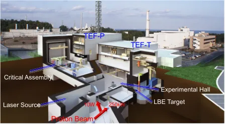
As shown in Fig. 2, TEF consists of two individ-ual buildings: ADS Target Test Facility (TEF-T) [3] and Transmutation Physics Experimental Facility (TEF-P) [4]. The two buildings are connected by a beam transport line with a low power beam extraction mechanism using a laser beam. TEF-T is planned as a material irradiation facility which can accept a maximum 400 MeV - 250 kW proton beam on a LBE spallation target. It also has an availability to use for various purposes such as measure-ment of the reaction cross sections of MA and structural materials, medical isotope production and so on. TEF-P is a facility with critical/subcritical assembly to study neutronics and controllability of ADS. Using these two facilities, basic physical properties of subcritical system and engineering tests of spallation target will be studied.
Fig. 2 Transmutation Experimental Facility.
R&Ds for several important technologies required to build the facilities are also performed, such as laser charge ex-change technique to extract a very low power beam for re-actor physics experiments, a remote handling method to load MA bearing fuel into the critical/subcritical assem-bly, the spallation and activation product removal method especially for the polonium, and so on.
3.1
R
&
Ds for TEF-T
The main purpose of TEF-T is to obtain the data to evaluate the actual lifetime of beam window. TEF-T mainly consists of a spallation target, a cooling circuit, and hot cells to handle the spent target and irradiation test pieces. A proton beam current density of 20µA/cm2,
which is almost the same as the future ADS design, was adopted as a reference. The irradiation performance of the reference case was evaluated around 8 DPA/yr by 400 MeV - 250 kW beam irradiation. This value is about 20% of DPA considered in the beam window of JAEA-ADS. Further optimization of the target design to increase DPA is underway.
When LBE is irradiated by high energy protons or neutrons, polonium isotopes will be accumulated and they should be carefully controlled. The removal method of polonium was studied for the design of exhaust circuit of TEF-T. An equilibrium vaporization test of polonium from liquid Pb-Bi was performed and equilibrium vaporiza-tion characteristics were measured by transpiravaporiza-tion method with LBE, which was irradiated at the JAEA/JMTR [5]. It was shown that at the low temperature around 450◦C, which considered as a standard operational condition of TEF-T and future ADS, most accumulated polonium re-mained in LBE as a chemical compound with Pb or Bi which is much harder to evaporate than elemental polo-nium.
Another experiment to recover evaporated polonium in the exhaust circuit was performed [6]. LBE samples were irradiated at the JAEA/JRR-4 and were heated in a special vacuum vessel up to 690◦C. By adopting the multi-layered filter, which consists of the stainless steel meshes with two different finenesses, escaping polonium can be decreased to 1/400.
3.2
Design of high power spallation target
for TEF-T
A high power spallation target, which will be mainly used for material irradiation of candidate materials for a beam window of full-scale ADS, is an essential issue to realize a TEF-T. To set up the beam parameters, future ADS concepts are taken into account. In the reference case of the target, proton beam current density of 20µA/cm2,
which equals to the maximum beam current density of JAEA-proposed 800 MWthADS, was assumed.
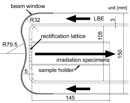
Fig. 3 Prototype LBE spallation target for TEF-T.
performed. The analysis was done by considering a cur-rent density and shape of the incident proton beam into the target, and the thermal-fluid behaviour of LBE around the beam window as a function of flow rate and inlet temper-ature of LBE. The thickness of the beam window is also considered parametrically. After the temperature distribu-tion analysis, structural strength of the beam window is determined to evaluate a soundness of the target.
A concave shape beam window was used for this anal-ysis. The prototype design of the beam window for TEF target system was shown in Fig. 3.
The material of beam window would be type 316 stainless steel as a primary candidate. The concave sec-tion in the center part of the target was connected to the convex section in the terminal part, and finally, it was con-nected to the straight tube. In the analysis, the thickness of beam window was parametrically set to 3 or 2 mm. A straight tube part has coaxially arranged annular and tube type channels. The inner diameters of the outside tube and inside tube were set to 150 mm and 105 mm, respectively. The total length of the analysis region was 600 mm, which corresponds to an effective target depth for 400 MeV pro-ton injection. An irradiation sample holder, which was in-stalled in the inner tube, holds eight irradiation specimens in the horizontal direction. The size of each specimen was 40×145×2 mm. The rectification lattice having the aper-ture of the plural squares type was installed at the front-end of the sample holder. A slit of 2 mm in width was arranged along the side of the rectification lattice to cool offthe sam-ple holder by flowing LBE.
The thermal-fluid behavior of the target was calcu-lated by the STAR-CD with a detailed three-dimensional model. The quarter-part model was set to tetra metric type and the divided face was set to a reflected image condition in the CFD analysis. In this calculation model, a hexahe-dral element was used and the total number of the elements was about 220,000. At first, LBE flowed through the an-nular region and it joined in the center of the beam
win-Fig. 4 Temperature profile in beam window.
dow, and then, turned over and flowed in the inner tube after having passed a rectification lattice and an irradiation sample. In a default condition, the flow rate at the inlet of annulus region was 1 liter/sec, and this was equivalent to the flow velocity of 0.125 m/sec. LBE flow is easy to form a complicated turbulent flow. Therefore, the standard k-ε model for high Re number type was used for a tur-bulence model. A heat deposition given by the incident proton beam, which was analyzed by a hadronic cascade code PHITS [7], was used for CFD analysis. The inter-nal pressure to the inside of the beam window was set to 0.3 MPa in consideration of the flowing LBE and the cover gas. On the outer wall of the beam window and the border of the atmosphere, release of the radiant heat was consid-ered. In this analysis, the embrittlement of the structural materials by the irradiation was not considered. Based on the results provided by CFD analysis, the analysis to ver-ify the feasibility of the beam window was performed by ABAQUS code, the computational code for the finite ele-ment method. The operating conditions for the first stage of material irradiation in TEF were decided by a result of the analysis on each condition.
The CFD analyses were performed by changing flow rates from 1 to 4 liter/sec. In each case, a dead region was commonly formed in the center of the inside of beam win-dow. The maximum velocity of LBE was confirmed at the rectification lattice part and was approximately 1.2 m/sec in the case of the inlet flow rate of 1 liter/sec. When the in-let flow rate increases to 4 liter/sec, the maximum velocity in the target reached 4.8 m/sec and cannot be applied be-cause the fluid vibration by LBE was concerned as well as the acceleration of erosion and/or corrosion of the material. One of the results, which is shown in Fig. 4, was the temperature profile on the beam window by chang-ing the thickness of the window from 2 mm to 3 mm with 1 liter/sec of LBE flow.
of the window were 65◦C and 37◦C in the case of 3 mm thick window and 2 mm thick window, respectively. From these results, it was disclosed that a condition of 2 mm was desirable.
The temperature and thermal stress for the steady state was estimated using ABAQUS code. In the ABAQUS code, only a beam window was modelled as the cylinder-slab geometry. The model consisted of 1,896 4-node axial-symmetric elements. For the analysis, results by STAR-CD were converted to the temperature of each node. From the analysis result, the stress strength reached the maxi-mum value of 190 MPa on the outer surface of the beam window. When the maximum temperature of the beam window is adopted to 470◦C from the result of STAR-CD, these stresses were lower than the tolerance level of the stress strength of the materials for a fast reactor, which sets less than 294 MPa, and hence, the feasibility of a designed beam window was confirmed.
3.3
Outline of TEF-P
Several neutronic experiments for ADS have been per-formed in both Europe [8, 9] and Japan. In Japan, subcrit-ical experiments were performed at the Fast Critsubcrit-ical As-sembly (FCA) in JAEA/Tokai with a252Cf neutron source
and a DT neutron source. Subcritical experiments with a thermal subcritical core driven by 150 MeV protons are be-ing performed at Kyoto University Research Reactor Insti-tute. There have been, however, no subcritical experiments combined with a spallation source installed inside the sub-critical fast-neutron core. The purposes to build TEF-P are (1) Study on reactor physics aspects of the subcritical core driven by a spallation source, (2) Demonstration of the controllability of the subcritical core including a power control by the proton beam power adjustment, and (3) In-vestigation of the transmutation performance of the sub-critical core using certain amount of MA and LLFP.
TEF-P is designed with referring to FCA, the hori-zontal table-split type critical assembly with a rectangular lattice matrix, to utilize operation experiences and existing experimental data of FCA. In this concept, the plate-type fuel for FCA with various simulation materials such as lead and sodium for coolant, tungsten for solid target, ZrH for moderator, B4C for absorber, and AlN for simulating
ni-tride fuel, can be commonly used at TEF-P. The proton beam will be introduced horizontally at the center of the fixed half assembly and various kinds of spallation targets can be installed at various axial position of the radial center of the subcritical core.
In the experiment with a proton beam, the effective multiplication factor (keff) of the assembly will be kept less
than 0.98. One proton with energy of 400 MeV produces tens of neutrons by the spallation reaction with a heavy metal target such as lead. The 10 W proton beam corre-sponds to the source strength of 1012neutrons/sec, which
have enough strength to measure the neutronic
character-istics.
From the viewpoint of the neutronic analyses for sub-critical systems, it is desirable to make the core sub-critical in order to ensure the quality of experimental data of the sub-criticality and the reactivity worth. So, the subcritical core can be make critical condition when the proton beam is suppressed.
As for the transmutation characteristics of MA and LLFP, fission chambers and activation foils are used to measure the transmutation rates. The cross section data of MA and LLFP for high energy region (up to several hun-dreds MeV) can be measured by the Time of Flight (TOF) technique with the proton beam of about 1 ns pulse width which can be delivered by a special beam extraction device using an Nd:YAG laser source [10]. Several kinds of MA and LLFP samples are also prepared to measure their reac-tivity worth, which is important for the integral validation of cross section data.
One of the main purposes of TEF-P is to perform in-tegral experiments using MA because the present accuracy of nuclear data is not sufficient for ADS design [11]. To improve the accuracy of the nuclear data especially for MA, both the differential experiments and the integral ex-periments are necessary, while the integral exex-periments on MA are more difficult than those on the major actinides. The effectiveness of MA-loaded experiments with a certain amount of MA was discussed [12]. In the procedure, data of virtual experiments using TEF-P are determined to esti-mate the reduction of the errors in the effective cross sec-tions. The data by TEF-P was assumed to be equal to the calculation result, and experimental error was taken from the past experiments in FCA. By using a certain amount of MA, which is about order of kg, typical improvement was observed.
4. Conclusion
JAEA has been promoting various R&Ds on ADS. As for the basic experimental studies necessary for future ADS construction, a plan to build Transmutation Experi-mental Facility has been proposed. The design optimiza-tion of TEF-T to improve irradiaoptimiza-tion performance, includ-ing R&D for polonium management, was carried out. The effectiveness of TEF-P experiments using a certain amount of MA was assessed quantitatively.
[1] T. Sasaet al., Nucl. Eng. Des.230, 209 (2004). [2] K. Tsujimotoet al., Nucl. Tech.161, 315 (2008).
[3] T. Sasaet al., “Conceptual Study of Transmutation Experi-mental Facility (2) Study on ADS Target Test Facility” (in Japanese), JAERI-Tech 2005-021 (2005).
[4] H. Oigawaet al., “Conceptual Design of Transmutation Ex-perimental Facility”, Proc. Global2001, Paris, France (CD-ROM, 2001).
[5] S. Ohnoet al., J. Nucl. Sci. Technol.43, 1359 (2006). [6] T. Obara, Y. Yamazawa and T. Sasa, Progress in Nuclear
[7] K. Niitaet al., “PHITS: Particle and Heavy Ion Transport code System, Version 2.23”, JAEA-Data/Code 2010-022 (2010).
[8] R. Souleet al., Nucl. Sci. Eng.148, 124 (2004).
[9] W. Uyttenhoveet al., Annuals of Nuclear Energy 38, 7, 1519 (2011).
[10] T. Tomisawaet al., “Investigation of Photo Neutralization Efficiency of High Intensity H-Beam with Nd:YAG Laser
in J-PARC”, Proc. of 7th European Workshop on Beam Diagnostics and Instrumentation for Particle Accelerators (DIPAC 2005), 275-277 (2005).