ELECTRONICALLY REFRIGERATOR
TEMPERATURE CONTROL
Sana Naikwadi
1, Prof. Mrs. Sayali Rawat
2Department of Electronics & Telecommunication Engineering,
Bhivarabai Sawant Institute Of Technology & Research,
Wagholi. Savitribai Phule Pune University (India)
ABSTRACT
There is an enormous future for efficient microcontrollers (MCUs) within the appliance trade because the worth of little pin count; little memory devices reach antecedent unachievable levels. a mixture of increased shopper demand for a lot of refined appliances and therefore the demand for competitive differentiation is driving the adoption of natural philosophy inside the appliance trade. Some refrigerators still have a basic mechanical device circuit that controls the temperature. Mechanical device are less energy economical, the govt norms for the energy potency rating are getting rigorous conjointly the client expectation regarding energy consumption of appliance are lower, thus there's want of energy economical icebox temperature management. MCUs supply cheap thanks to add innovative differentiating options and improve the potency of the appliance whereas continued to scale back system value. Within the past this evolution had not been potential for prime volume merchandise owing to the comparatively high worth of little MCUs and mechanical device controllers. Several appliances nowadays still solely use distinct parts to supply terribly basic management inside the system. this can be blessings to the appliance trade of employing a little extremely integrated MCU over distinct based mostly management solutions, and thence the electronic icebox temperature controller are often the answer.
Keywords: MC9RS08KA2 (Freescale MCU), One Potentiometer, Thermister, Codewarrior 6.3 Tool
I. INTRODUCTION
Some refrigerators still have a basic electromechanical circuit that controls the temperature. Electromechanical
are less energy efficient, the government norms for the energy efficiency rating are becoming stringent also the
customer expectation about energy consumption of home appliance are lower, so there is need of energy
efficient refrigerator temperature control. Current electromechanical controllers have limitations for the efficient
control. The electronic refrigerator temperature controller can be the solution. The existing electromechanical
refrigerator temperature controllers are not cost effective, so there is need of low cost electronic refrigerator
temperature controller to improve the energy efficiency of refrigerator.
1.1 Basic Refrigeration Cycle
Liquids absorb heat ones modified from liquid to gas Gases offer heat ones modified from gas to liquid.
For Associate degree air con system to control with economy, the refrigerant should be used repeatedly. For this
Fig.1 Principles of Refrigeration
The gas then flows to the condenser. Here the gas condenses to a liquid, and offers off its heat to the skin
air.
The liquid then moves to the enlargement valve beneath air mass. This valve restricts the flow of the fluid,
and lowers its pressure because it leaves the enlargement valve.
The unaggressive liquid then moves to the evaporator, wherever heat from the within air is absorbed and
changes it from a liquid to a gas.
As a hot unaggressive gas, the refrigerant moves to the mechanical device wherever the whole cycle is
continual.
Note that the four-part cycle is split at the middle into a high aspect and a coffee aspect side this refers to the
pressures of the refrigerant in all sides of the system.
II. PROPOSED SYSTEM
The DC voltage is needed for operational the relay coil management electronic equipment is generated from AC
solely by employing a standard AC/DC power offer. As there should always be a minimum of 3v differential
between the inputs and controlled output during3 terminal regulator to keep up regulation. A basic resistance
with one resistance and one thermoresistor is employed to implement the temperature detector.
The
thermister resistance depends on the temperature. For every temperature, we've a special voltage within the divider. Thisprice is effectively measured with the ADC enforced by computer code that uses one resistance, one electrical
condenser, and therefore the analog comparator enclosed within the MC9RS08KA2 MCU.
The icebox temperature management has four positions. The management switches on the relay once the
Fig. 2 Block Diagram
For example, the refrigerator’s temperature management has four positions, the vary of everyone is: • Position 4: zero °C – one °C
• Position 3: one °C – two °C • Position two: 2 °C – three °C • Position 1: three °C – four °C
When the temperature position is one, if the temperature is beyond four °C, the relay is closed, and therefore the
icebox mechanical device is on. Next, once the temperature reaches two.5 °C, the applying opens the relay and
therefore the mechanical device stops.
III. IMPLEMENTATION & RESULT
The temperature management is enforced with one potentiometer and a electrical condenser connected to 1
MC9RS08KA2 MCU I/O pin. The temperature detector may be a basic resistance fashioned by a resistance and
a thermister. The output is associate I/O pin connected to a relay that switches the availability of the icebox. The
flow of the program consists of reading the management wheel price followed by reading the detector voltage
and, finally, change the output ON or OFF per the management and detector values.
3. 1 Management Price
The icebox temperature management may be a basic RC network connected to associate I/O pin. By
measurement the charging time of the RC network, we are able to verify the potentiometer resistance, and thus,
the worth you entered. The charge curve of the RC network is employed to see the time the curve takes to travel
from zero V to the input-high voltage (VIH). This technique is employed as a result of the MC9RS08KA2 MCU
doesn't have associate integrated analog-to digital device (ADC).
The first step is configuring the management pin as output. Set the pin price to zero to discharge the capacitance.
After the capacitance is absolutely discharged, modification the management pin direction to associate degree
input. The capacitance starts charging to VDD. When the voltage of the capacitance gets to VIH, the pin state
changes from zero to one. A resistance (potentiometer) is employed to change the time the capacitance takes to
The electrical device voltage is given by the subsequent equation:
VCC=VDD (1- )………...…….. (1)
Solving for time
T = - rc In (1- )………..………. (2)
• Vc — Voltage of the electrical device • VDD — offer voltage of RC network • t — Time (seconds)
• r — Resistance • c – Electrical device
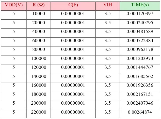
A 220 kΩ potentiometer and ten nF electrical devices were utilized in this application note. From the
MC9RS08KA2 datasheet, we all know that once VDD > two.3 V, the VIH for the inputs is zero.70 x VDD.
If the MC9RS08 MCU is equipped 5 V then:
VIH = 0.70 x VDD = (0.70 x 5) = 3.5 V
Table one show the distinction in time victimisation the on top of with totally different resistance industrial
values
Table 1 Time Result According Resistance Value
VDD(V) R (Ω) C(F) VIH TIME(s)
5 10000 0.00000001 3.5 0.000120397
5 20000 0.00000001 3.5 0.000240795
5 40000 0.00000001 3.5 0.000481589
5 60000 0.00000001 3.5 0.000722384
5 80000 0.00000001 3.5 0.000963178
5 100000 0.00000001 3.5 0.001203973
5 120000 0.00000001 3.5 0.001444767
5 140000 0.00000001 3.5 0.001685562
5 160000 0.00000001 3.5 0.001926356
5 180000 0.00000001 3.5 0.002167151
5 200000 0.00000001 3.5 0.002407946
Fig. 4 Curve with different resister
3.2 Temperature Detector
A basic resistance with one electrical device and one thermoresistor is employed to implement the temperature
sensor. The thermoresistor resistance depends on the temperature. For every temperature, we have a different
voltage within the divider. This price is effectively measured with the ADC enforced by software package that
uses one electrical device, one electrical device, and therefore the analog comparator enclosed within the
MC9RS08KA2 MCU.
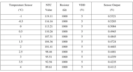
The resistance consists of the thermoresistor NCP18WB333J03RB and a one kilo ohms electrical device. It is
better to own a giant variation within the output voltage of the detector with somewhat variation within the
temperature.
The supply voltage of the RC network during this application note is five V and therefore the output voltage of
the detector can be calculated with consequent equation.
Vout = Vdd (NTC/ (NTC+R)) =5(NTC/ (NTC+1k))………..… (3)
According to the thermoresistor specifications, the resistance vary is between eighty nine.61 Ω to 116.16 Ω in a
range of four °C to –0.5 °C.
Table 2 Sensor Output Voltage
Temperature Sensor
(°C)
NTC
Value
Resister
(Ω)
VDD
(V)
Sensor Output
(V)
-1 119.11 1000 5 0.5321
-0.5 116.16 1000 5 0.5203
0 113.21 1000 5 0.5084
0.5 110.26 1000 5 0.4965
1 107.31 1000 5 0.4845
1.5 104.36 1000 5 0.4724
2 101.41 1000 5 0.4603
2.5 98.46 1000 5 0.4481
3 95.51 1000 5 0.4359
3.5 92.56 1000 5 0.4235
Fig. 5 Sensor Value Input (ADC by Software)
The formula to calculate the time taken for the capacitance to charge is that the same because the temperature
management formula:
VC =Vdd (1- e^ (-1/rc))………..……….. (4)
Solving for time
t= - rc ln (1 - )………..… (5)
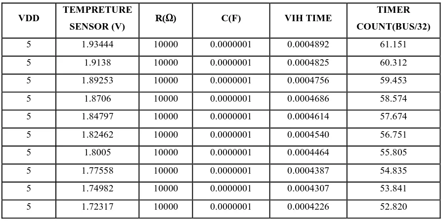
But, for the ADC by computer code the RC network is fastened. During this case, the resistance price is ten kΩ.
The capacitor is zero.1 μF.
Based on the bus speed (8 MHz for this application), it is effective to build a table with the timer value
according the sensor voltage.
To calculate the timer counts of each sensor voltage the next formula must be applied:
Timer Counts = VIH time (BusClock/prescaler)……… (6)
Table 3 Temperature, Sensor Output, and Microcontroller Counts
VDD TEMPRETURE
SENSOR (V) R(Ω) C(F) VIH TIME
TIMER
COUNT(BUS/32)
5 1.93444 10000 0.0000001 0.0004892 61.151
5 1.9138 10000 0.0000001 0.0004825 60.312
5 1.89253 10000 0.0000001 0.0004756 59.453
5 1.8706 10000 0.0000001 0.0004686 58.574
5 1.84797 10000 0.0000001 0.0004614 57.674
5 1.82462 10000 0.0000001 0.0004540 56.751
5 1.8005 10000 0.0000001 0.0004464 55.805
5 1.77558 10000 0.0000001 0.0004387 54.835
5 1.74982 10000 0.0000001 0.0004307 53.841
3.3 Temperature Management Application
The refrigerator’s temperature management has four positions, that vary of everyone is: • Position 4: zero °C – one °C
• Position 3: one °C – two °C • Position 2: two °C – three °C • Position 1: three °C – four °C
The management switches on the relay once the temperature is over vary. It switches it off once the temperature
reaches the window worth. Because of temperature inertia, the window temperature is one.5 °C. Figure half
dozen shows the window and also the values from it.
Fig. 6 Temperature Control Range
For example, once the temperature position is one, if the temperature is beyond four °C, the relay is closed, and
the icebox mechanical device is on and at the same time heater is off. Next, once the temperature reaches two.5
°C, the applying opens the relay and therefore the mechanical device stops and hence heater start working. This
guarantees that the temperature is stable for long periods of your time between the ranges and, no matter what;
the temperature isn't quite four °C. Each temperature limit may be simply modified within the definition a part
of the most code.
V. CONCLUSION
This paper shows a way to implement a straightforward on-off system with a low-end 8-bit microcontroller. The
wants for associate MCU-based answer, providing intelligence, potency and complicated options, have become
a lot of necessary within the appliance business, due to:
[2] ―An Early History of Comfort Heating". The NEWS Magazine Troy, Michigan: BNP Media. November
6, 2001. Retrieved November 2, 2014
[3] "Thermostat Maker Deploys Climate Control Against Climate Change". America.gov. Retrieved October
3, 2009.
[4] "Johnson Controls Inc. | History". Johnsoncontrols.com. November 7, 2007. Retrieved October 3, 2009
[5] Falk, Cynthia G. (2012). Barns of New York: Rural Architecture of the Empire State (paperback) (First ed) Ithaca, New York: Cornell University Press (published May 1, 2012). ISBN 978-0-8014-7780-5
Retrieved November 2, 2014.
[6] http://www.freescale.com MC9RS08KA2 Series Data Sheet
[7] http://www.inventionsinfo. Ev/2009/06 electric refrigerator.html
[8] GE Appliances refrigerator adjusting temperature control
[9] Calm, J.M., Hourahan, G.C., 2001. Refrigerant data summery
[10] Calm, J.M., Hourahan, G.C., 2001. Refrigerant data summery Engineering Systems 18, 74–88
[11] Jennifer Fonder (Development) Ag Power Web Enhanced Course Materials © 2002-2006 Pete
Hoffman (Content)
[12] Appliance 411 information @Daniel O’Neill 1997-2011
[13] Inga Harris. Replacement of Mechanical, Electromechanical and Discreet Logic in Appliances with
MCUs
[14] How to Fix a Refrigerator and Freezer That's Too Warm [email protected]
[15] www.st.com/.../NEW%20ELECTRONIC%20THERMOSTAT%20SOLU