44 |
P a g e
BLDC MOTOR DRIVE SYSTEM USING MODIFIED
PULSE WIDTH MODULATION TECHNIQUE USING
Z-SOURCE INVERTER CONTROL SCHEME
Dr. S. Siva Prasad
1, A.B Bhavana Reddy
2, K..Rajeev
3 1Professor, Dept. of EEE ,Vidya Jyothi Institute of Technology, Hyderabad.
2,3Asst. Professor, Dept. of EEE ,Vidya Jyothi Institute of Technology.
ABSTRACT
Modified pulse width modulation technique for Z-source inverter based BLDC motor is proposed and analyzed
in this project.The Z-source inverter can be used as Buck/Boost converter with lower cost and high efficiency.
BLDC motors are used in electric vehicles where portability and efficiency are required. This drive system
provides advantages of both BLDC motors and Z-source inverter, and can be used in fuel cell system and other
adjustable speed drive application. In this project principle of modified pulse width modulation technique is
implemented and simulated. The model of a three phase Z-source inverter has been discussed based on modified
pulse with modulation technique. The simulation of Z-source inverter based BLDC motor is done A using the
MATLAB/SIMULINK
Keywords-Brushless dc motor(BLDC), z-source inverter, VSI, CSI, electric drive system
I.
INTRODUCTION
The fuel cell, a clean energy source, provides much higher efficiency than the traditional internal combustion
engine (ICE), which potentially makes the fuel cell electric drive system the next-generation traction system [2].
The output voltage of the fuel cell declines dramatically when the output current increases. The output voltage
of the fuel cell at the maximum power point is about half of the open load voltage.
Fuel cell vehicle (FCV) traction drives require high voltage at high speed and high power. Thus to achieve high
speed and high power, the inverter and the motor must be oversized if only a traditional pulse width modulation
(PWM) inverter is used as the power converter.
The two major types of drives are known as voltage source inverter (VSI) and current source inverter (CSI) [1].
In industrial markets, the VSI design has proven to be more efficient, have higher reliability and faster dynamic
response, and be capable of running motors without de-rating. VSI fully integrated design saves money with
higher efficiencies, minimizing install time, eliminating interconnect power cabling costs, and reducing building
floor space. Efficiencies are 97% with high power factor through all load and speed ranges. Fast dynamic
417 |
P a g e
II.
MODULATION OF THREE-PHASE-LEG Z-SOURCE INVERTER
The For a three-phase-leg VSI, both continuous switching (e.g. centred SVM) and discontinuous switching (e.g.
60 deg- discontinuous
PWM) are possible with each having its own unique null placement at the start and end of a switching cycle T
and characteristic harmonic spectrum. This section now extends the analysis to derive various continuous and
discontinuous PWM strategies for a three phase leg Z-source inverter with each having the same characteristic
spectrum as its conventional counterpart [2-3].
The fifteen switching states of a three-phase leg Z-source inverter. In addition to the six active and two null
states associated with a conventional VSI, the Z- source inverter has seven shoot-through states representing the
short-circuiting of a phase-leg (shoot-through states E1 to E3), two phase-legs (shoot-through states E4 to E6) or
all three phase-legs (shoot through state E7).These shoot-through states again boost the dc link capacitor
voltages and can partially supplement the null states within a fixed switching cycle without altering the
normalized volt-sec average, since both states similarly short circuit the inverter three-phase output terminals,
producing 0V across the ac load. Shoot-through states can therefore be inserted to existing PWM state patterns
of a conventional VSI to derive different modulation strategies for controlling a three phase- leg Z-source
inverter.
Fig.1 Continuous modulation of three-phase-leg Z-source inverter
2.1 Z-Source Inverter
To overcome the above problems of the traditional V-source and I-source inverter, this project presents an
impedance-source (or impedance-fed) power inverter (abbreviated as Z-source inverter) and its control method
for implementing dc-to-ac, ac-to-dc, ac-to-ac, and dc-to-dc power conversion [8]. It employs a unique
impedance network (or circuit) to couple the converter main circuit to the power source, load, or another
converter, for providing unique features that cannot be observed in the traditional V-source and I-source inverter
418 |
P a g e
Fig.2 General structure of the Z-source inverter
III.
Z – SOURCE INVERTER BASED BLDC MOTOR DRIVE SYSTEM
Fig .3.1 shows the main circuit of the proposed Z- source inverter based BLDC drive system. a voltage-type Z-
source inverter is utilized instead of the traditional voltage source inverter(VSI) or current source inverter(CSI),
to feed electric energy from the dc source to the brushless dc motor to gain the buck/boost ability, the pulse
width modulation[4].
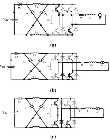
According to the operation principle of BLDC, two phases are conducted in the non commutation stage fig 3.2
shows an equivalent circuits when the phase a and b windings are conducted with the current flows form phase a
winding to phase b winding the shoot through states can be generated via showing either any one arm or both
arms in the bridge. The burs line and arrows indicates the path and direction of the currents, respectively from
fig 3.(a) and 3.(b).It can be seen that only two semiconductor devices (IGBT or the anti parallel diode) in
different arms of the bridge are conducted in the non shoot through modes
(a)
(b)
(c)
Fig.3 Equivalent circuits during non – commutation stage
419 |
P a g e
(PWM) method should be used to control the source inverter to generate shoot-through states. Unlike theZ-source inverter based ASD system with induction machines, the output currents of the Z-Z-source inverter in the
proposed BLDC drive system are composed of square waveforms of 1200 electrical degree. Consequently, the operation principle, the modeling method and the control are all different from the Z-source inverter based ASD
system with induction machines.
Fig. 4 Z – source inverter based BLDC Motor
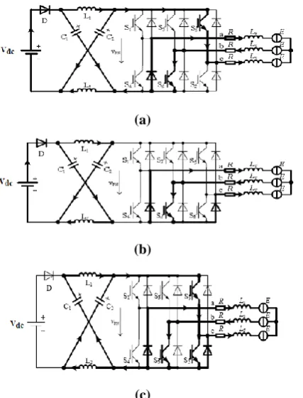
In the phase commutation stage, the switch S1 is shut off, and the switch S5 is turned on at the same time. There
are three devices conducted in the non-through modes, as shown in Fig 5. (a) and (b).While in the
shoot-through modes, five devices may be conducted when the shoot-shoot-through occurs in one phase arm, as shown in
Fig 5.(c). And seven devices maybe conducted if the shoot-through occurs in two phase arms. It is worth noting
that, the shoot-through states should be generated by gating on the lower switch only when the inverter output is
in „active‟ state. For example, in Fig 5(c),the switches S1 and S6 are triggered to feed the phase a and b
windings, the switch S4 is used to shorted the arm, and the sketch of gating signals to the witches S1, S6 and S4
can be seen in Fig.5.
(a)
(b)
(c)
Fig.5 Equivalent circuit during phase commutation stage (a) active state (b) Open state (c)
420 |
P a g e
Fig.6 Waveform of the Gate SignalsTaking the duty ratio of S1 is D1 and the duty ratio of S2 is D2 the average output voltage of the inverter is
dc
V
D
D
D
V
.
2
1
44 1 0
Where 0 < D1,
0 < D4< 0.5,
D4< D1 and
4 4 1
2
1
0
D
D
D
It can be seen that the output voltage can be bucked and boosted within a wide range. A straight line is used to
control the shoot-through states. When the triangular waveform is lower than the straight line, the circuit turns
into shoot through modes.
IV.
STATE SPACE MODEL
State-space models have been broadly applied to study macroeconomic and financial problems. For example,
they have been applied to model unobserved trends, to model transition from one economic structure to another,
to forecasting models, to study wage-rate behaviors, to estimate expected inaction, and to model time-varying
monetary reaction functions [6-7].
4.1 Modeling of the Impedance Source Network
Generally, the Z-source network can operate in six possible states, in which three states are desired while the
other three are undesirable. And the undesirable states can be avoided by choosing appropriate values of the
inductors and capacitors of the impedance network. It is supposed that only the three desired states are
considered in the following analysis [4]. The desired open state, active state and shoot-through state are
illustrated in Fig 7(a), (b) and (c), respectively [5].
Assuming that the Z-source network is symmetrical, that is L1 = L2 = L, C1 = C2 =C, iL1 = iL2 = iL and vC1 = vC2
= vC2.
421 |
P a g e
The state variables are chosen as iL and vC the input variables are Vdc and iPN and the output variables aredenoted by vPN and idc. Then from Fig.7(a), the state equations and output equations during the open state can
be written as
PN dc c L t c Li
V
L
L
v
i
C
L
d
dv
dt
di
0
0
0
1
0
1
1
0
PN dc c L dc PNi
V
v
i
i
V
0
0
0
1
0
2
2
0
(1)From Fig.7(b) the state and output equations during the active state are
PN dc c L c Li
V
C
L
v
i
C
L
dt
dv
dt
di
1
0
0
1
0
1
1
0
PN dc c L dc PNi
V
v
i
i
V
1
0
0
1
0
2
2
0
( 2)And from Fig.7(c), the state equations and output equations during the shoot-through state can be expressed as
PN dc c L c Li
V
v
i
C
L
dt
dv
dt
di
0
0
0
0
0
1
1
0
PN dc c L dc PNi
V
v
i
i
V
0
0
0
0
0
0
0
0
(3)V.
SIMULINK
The performance of the z-source inverter for BLDC motor drive using modified pulse width modulation
technique has been established. Simulation model has been established using Matlab/Simulink. The simulation
circuit arrangement is shown in fig 8. The ideal DC voltage source of 300V is taken and simulation studies have
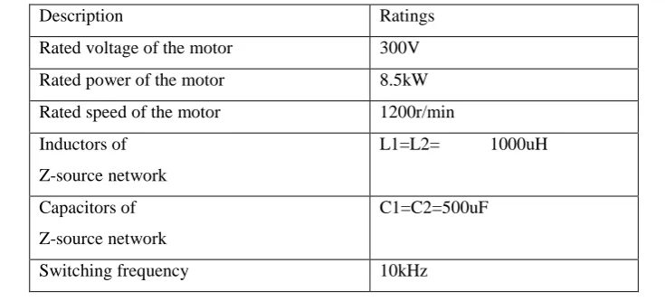
been performed.The main parameters of the simulation model are listed below in table I.
Table. I Main Simulation Parameters
Description Ratings
Rated voltage of the motor 300V
Rated power of the motor 8.5kW
Rated speed of the motor 1200r/min
Inductors of
Z-source network
L1=L2= 1000uH
Capacitors of
Z-source network
C1=C2=500uF
422 |
P a g e
Form ease of analysis, the dynamic response of the fuel cell is ignored and the fuel cell is modeled as an ideal dcvoltage source of 300V, which is lower than the rated voltage of the PMBDCM. The speed and current closed
loop control is applied to control the PMBDCM, and simulation studies have been performed with and without
shoot-through mode.
5.1 Simulink Model
Fig.8 Simulation model of Z-Source Inverter modified PWM Control Based BLDC motor
5.2 Subsystem for Modified Pulse Width Modulation Control
Fig.9 Subsystem for Modified Pulse Width Modulation Control
5.3 Simulation results using modified PWM Technique
The simulation was run for 2 seconds. The waveforms of the stator phase current, capacitor voltage, rotor speed,
torque, inductor current are observed.
423 |
P a g e
The fig.10 shows stator phase current waveform without shoot through state at load 55Nm. The amplitude of thestator phase current cannot maintain at the rated value due to the less input dc voltage compared to the rated
voltage of the BLDC motor.
Fig.11 Capacitor voltage without shoot through state
The fig.11 shows the capacitor voltage waveform without shoot through state at load 55Nm.Capacitor is charged
to 300 voltage which is equal to the input dc voltage.
Fig.12 Rotor speed without shoot through state
The above fig.12shows the rotor speed waveform without shoot through state at load 55Nm. Due to the absence
of shoot through state the rotor speed reduces to 1000 rpm which is less than rated speed that is 1200 rpm.
Fig.13 Torque without shoot through state
The fig.13 shows the torque waveform without shoot through state at load 55Nm. Due to the absence of shoot
through state the large torque ripples are formed.
Fig.14 Inductor current without shoot through state
The fig.14 shows the inductor current waveform without shoot through state at load 55Nm.
Fig.15 Stator phase current with shoot through state
0 0.1 0.2 0.3 0.4 0.5 0.6 0.7 0.8 0.9 1
-50 0 50 100 150 200 250 300 350 400 450
Time(sec)
Ca
pa
ci
to
r V
olta
ge
(V
)
0 0.1 0.2 0.3 0.4 0.5 0.6 0.7 0.8 0.9 1
0 200 400 600 800 1000 1200
Time(sec)
Sp
ee
d(
rp
m
)
0 0.1 0.2 0.3 0.4 0.5 0.6 0.7 0.8 0.9 1
0 10 20 30 40 50 60
Time(sec)
To
rq
ue
(N
m
)
0 0.1 0.2 0.3 0.4 0.5 0.6 0.7 0.8 0.9 1
0 5 10 15 20 25 30 35
Time(sec)
In
du
ct
or
C
ur
re
nt(A
424 |
P a g e
The fig.15 shows the stator phase current waveform applying shoot through state with duty ratio d=0.2 at timet=1sec at load 55Nm.By applying shoot through state the stator phase current maintain rated value.
Fig.16 Capacitor voltage with shoot through state
The fig.16 shows the capacitor voltage waveform applying shoot through state with duty ratio d=0.2 at time
t=1sec at load 55Nm. Without shoot through state the capacitor voltage is 300V, with shoot through state of duty
ratio d=0.2 the capacitor voltage increases to 400V.
Fig.17 Rotor speed with shoot through state
The fig.17 shows the rotor speed waveform applying shoot through state with duty ratio d=0.2 at time t=1sec at
load 55Nm. Without shoot through state the rotor speed is 1000rpm, with shoot through state of duty ratio
d=0.2 the rotor speed increases to 1200 rpm.
Fig.18 Torque with shoot through state
The fig.18 shows the torque waveform applying shoot through state with duty ratio d=0.2 at time t=1sec at load
55Nm. By applying shoot through state the electro magnetic torque raises to rated value.
Fig.19 Inductor current with shoot through state
The fig.19 shows the inductor current waveform applying shoot through state with duty ratio d=0.2 at time
425 |
P a g e
VI.
CONCLUSIONS
Control scheme of z-source inverter based BLDC Motor drive system using modified pulse width modulation
has been simulated. The simulation studies have been performed with modified pulse width modulation
technique the simulation waveform of the phase currents, capacitor voltage, rotor speed, inductor current, torque
are observed.
REFERENCES
[1]. F. Z. Peng, “Z-Source Inverter,” IEEE Transactions on Industry Applications, 39(2), pp.504–510,
March/April 2003.
[2]. F. Z. Peng, Li Hui, Su Gui-Jia, J. S. Lawler, “Anew ZVS bidirectional dc-dc converter for fuel cell
and battery application,” IEEE Transactions on Power Electronics, 19(1), Jan. 2004.
[3]. M. Shen, A. Joseph, J. Wang, F. Z. Peng, and D. J. Adams, “Comparison of traditional inverter and
Z-Source inverter for fuel cell vehicles,” IEEE WP 2004, pp.125–132.
[4]. “Advanced PM brushless DC motor control and system for electric vehicles” Fang Lin Luo; Hock
Guan Yeo; Industry Applications Conference, 2000. Conference Record of the 2000 IEEE , vol.2, pp
1336 -1343, 2000
[5]. G. L. Tao, Z. Y. Ma, L. B. Zhou, and S. Hu, “Modeling and simulation of permanent magnet brushless
DC motor allowing for damping windings,” in Proc. IPEMC’2004, vol. 1, pp. 271-274, 2004.
[6]. F. Z. Peng, “Z-Source Inverter for Motor Drives,” in Proc. IEEE Power Electronics Specialists
Conference, pp. 249-254, 2004.
[7]. P. C. Loh, D. M. Vilathgamuwa, Y. S. Lai, G. T. Chua and Y. W. Li,“Pulse-width modulation of Z-source inverters”, IEEE Trans. Power Electron., vol. 20, pp. 1346-1355, Nov. 2005.
[8]. Fang. Z. Peng, Xiaoming Yuan, Xupeng Fang, and Zhaoming Qian, “Z source inverter for adjustable
426 |
P a g e
AUTHOR
DR. S.SIVA PRASAD, Professor, EEE has awarded Ph.D Electrical Engineering in 2012(February) from J. N. T. UNIVERSITY HYDERABAD and had his M.Tech with
specialization of Power Electronics in 2003.He has obtained his B.Tech Degree in
Electrical and Electronics Engineering from S V University. He is having 19 years of
Experience and currently working as Professor Vidya Jyothi Institute of Technology,
AzizNagar , Hyderabad , India . He received “Bharat Vibhushan Samman Puraskar” from “The Economic and Human Resource Development Association” in 2013 and received Young Investigator
Award in 2012. He has published about 60 technical papers in International and National Journals and
Conferences and filed one patent. He is Life member of ISTE and member of IEEE. His Research areas include
Power Electronics & Drives, PSD&FACTS Controllers.