AN APPROACH OF 3-LEVEL IMAGE
STAGANOGRAPHY USING DNA
SEQUENCE AND 3×3 MATRIX PIXEL
PAIR DIFFERENCING ALGORITHM
SUMAN CHAKRABORTY1
B.P.Poddar Institute of Management & Technology, 137,VIP Road,Kolkata-700081,India.
Prof. SAMIR K BANDYOPADHYAY
Vice Chancellor,, West Bengal University of Technology, Kolkata, India, [email protected].
Abstract:
In this paper proposed a method of image staganography by DNA sequence and 3×3 matrix pixel pair difference(3×3 MPPD).Here embedding of secret information into a image is done by 3×3 MPPD.This embedding procedure provide high PSNR,so,less distortion in stego-image.DNA sequence is use to encrypt as well as compress stego-image. Here secret information hide in three level depths – First level, embedding the secret information into cover-image, second level, transform the stego-image in DNA sequence and third level, compress the DNA sequence.Degree of security directly proportional with depth of security.
Keywords: DNA ; MPPD; Stego-imag ;Cover-image; Compression; Embedding; Range- table.
1. Introduction
Steganography is the art and science of writing hidden messages in such a way that no one, apart from the sender and intended recipient, suspects the existence of the message, a form of security through obscurity. The word steganography is of Greek origin and means "concealed writing" from the Greek words steganos
(στεγανός) meaning "covered or protected", and graphei (γραφή) meaning "writing". The first recorded use of
the term was in 1499 by Johannes Trithemius in his Steganographia, a treatise on cryptography and steganography disguised as a book on magic. Generally, messages will appear to be something else: images, articles, shopping lists, or some other covertext and, classically, the hidden message may be in invisible ink between the visible lines of a private letter [1].
DNA as the 'blueprint' that makes you look like you, and all your parts into all your parts - organs, bones, hair color, height, gender, skin color, every piece of you. DNA is a very tiny blueprint; just like millions of bits of information can be stored in a tiny computer part, millions of details about you can fit into your DNA. There is no part of you, no matter how large or small, that is not programmed to look that way, to 'do its job' a certain way, and to grow a certain way (age), by these details in your unique DNA. This blueprint tells your liver to look and work like a liver, tells your hair to look and grow like hair, your eyes to look and see like eyes, your joints to look and move like joints, and everything else to the smallest detail in your body[2].
DNA nucleotides are the small repeating units that, joined together by the millions into a long spiral ladder shape, form the DNA strand, also called a DNA molecule or double helix or, simply, DNA. [2]. There are only four substances a DNA base can be made out of; all those millions of bases, joining in twos to form millions of ladder rungs, are made up of only these four substances, in differing sequences. Yes, we're getting closer to sequencing! But not quite yet. First, we need to know about the little units that are being sequenced, the DNA bases [2].
DNA base pairings [2]
The goal of this paper is to develop a staganography procedure in which secret information hide in bigger depth.3×3 MPPV procedure used to embed secret information within Cover-image with less distortion than other pixel value difference(PVD) method. Outcome of MPPV procedure is Stego-image which further encrypted by DNA sequence. Less no. of bits required to represent any image if it’s encrypted by DNA sequence .This is the advantage of DNA encryption.
The remainder of the paper is organized as follows. In Section 2 Review works. In Section 3, flow diagram is presented. In Section 4, the description of proposed 3×3 MPPV algorithms is presented. In Section 5, description of 3-Level Image Staganography Algorithm. In Section 6, presents the experimental results .In Section 7, conclusion.
2. Related Works
2.1 FPPD (Five Pixel Pair Differencing method) System
This is implemented by dividing the cover image into 3 × 2 blocks of pixels. The cover image is a gray level image. Proposed herewith is that five pairs can be used to embed the secret data. Before using the proposed algorithm, pre-processing is required to partition the grey level cover image into nonoverlapping 3 × 2 blocks with 6 pixels as shown in
Figure-1.[3]
Figure 1.Pixel Block
As shown in Figure-1, each 3 x 2 block includes six pixels P(x,y) , P(x+1,y), P(x+2,y), P(x,y+1), P(x+1,y+1) and P(x+2,y+1)
where x and y are the pixel locations in the image. Let P(x,y) be the starting point, then five pixel pairs can be
formed as P0 =( P(x,y),P(x+1,y) ), P1 =(P(x,y),P(x+2,y) ), P2 = (P(x,y),P(x,y+1) ),P3 = (P(x,y),P(x+1,y+1) ) and P4 =
(P(x,y),P(x+1,y+2) ). When using the proposed FPPD method to embed the secret data, each pixel pair is modified as
P’i and a new difference value d’i for i = 0, 1,2,3,4 is calculated where d’i ranges from 0 to 255. So a range table
R, with n contiguous ranges, is designed and the table range is from 0 to 255.[3]
The new pixel values in each pair are different from their original ones. That is, five different pixel pairs are obtained namely P’0, P’1, P’2, P’3, P’4 from P0, P1, P2, P3, P4 respectively. One of the P’i is selected as the
reference point to offset the other pixel values. That is, two pixel values of one pair are used to adjust the pixel values of other five pairs and then a new 3x2 block of pixels is constructed. Selecting different reference points, results in varied distortion to the stego-image. Suppose that mi = d’i – di, where d’i and di are the difference
values of pixel pair i before and after embedding procedures. Then the pair having minimum |mi| is used as the
reference point.[3]
The details of data hiding steps are described as follows.
1. Calculate the difference values di(x,y) for the five pixel pairs in each block given by
d0(x,y) = P(x+1,y) – P(x,y)
d1(x,y) = P(x+2,y) – P(x,y)
d3(x,y) = P(x+1,y+1) – P(x,y)
d4(x,y) = P(x+2,y+1) – P(x,y)
2. Use | di(x,y) | where i = 0,1,2,3,4 to locate suitable range Rk in the designed range table. The ranges in the
range tables are taken as
(0,3),(4,7),(8,15),(16,31),(32,63),(64,127,(128,255 ))
3. Compute the amount of secrete bits ti that can be embedded in each pair using the corresponding range
given by Rj,k. The value ti can be estimated from the width wi,k of Ri,k , which is obtained as ti = | log2wi,k |
where width wi,k = Ui-li+1 and Ui and li are upper and lower boundaries of the range Ri. For each di (from d0-d4)
,the threshold is calculated as Ti = Ui – li-1 .For embedding the bits following rules are applied.[6]
I. If di _ Ti U Ri=1, No overlapping is required but b should be in the range of [ 0, d- li] so magnitude
of new difference is less than d. Maximum number of secrete bits are selected so that b≤ di- li
where b is decimal value. New difference d’i is li +b .
II. If di < Ti , b should be in the range [0,ui-1 – li-1] . Maximum number of secrete bits are b≤ d- li
where b is decimal value. If b≤ di- li , the new difference d’i is li +b otherwise d’i is li-1 +b .
4. Read ti bits from the binary secret data and transform the bit sequence into a decimal
value bi.
5. Calculate the new difference value d’i(x,y) given by
d’i = li +bi, if di(x,y) ≥ 0
d’i = -( li +bi ), if di(x,y) < 0 to replace the original difference di(x,y).
6. Modify the values of pixels in P’i by using the following equation (P’n , P’n+1) = ( Pn - | m/2 |, Pn+1 + | m/2 | )
where Pn and Pn+1 represents two pixels in the pair Pi and m is the difference between di and d’i. This is given
by m= d’i – di.
7. Use the pair with minimum | mi | as the optimal reference pair P’i(x,y) , then this selected point is used to offset
the other four pixel pairs. Thus calculate new values for all the six pixels in the block.
8. Check whether all the pixel values are in the range 0 to 255. If the one or more new pixel values are not in the range 0 to 255, adjust them such that the pixel values will be in the range 0 to 255. (If the pixel values are not adjusted in this way then the cover image is not useful for embedding the secret data).
9. Now, construct the new block from all pixel pairs with modified pixel values.[3]
Following algorithm describes how to retrieve the embedded secret data from the stego-image.
1. Partition the stego-image into 3x2 pixel blocks, and the partition order is the same as embedding stage. 2. Calculate in difference values separately for each block in the stego-image given by
d'0(x,y) = P(x+1,y) – P(x,y)
d’1(x,y) = P(x+2,y) – P(x,y)
d’2(x,y) = P(x,y+1) – P(x,y)
d’3(x,y) = P(x+1,y+1) – P(x,y)
d’4(x,y) = P(x+2,y+1) – P(x,y)
3. Use | d’i(x,y) | where i = 0,1,2,3,4 to locate suitable Rk,i in the designed range table
4. Compute the amount of secrete bits ti that can be embedded in each pair. For each di (from d0-d4) ,the
threshold is calculated as Ti = Ui – li-1. If | d’i(x,y) | < Ti , then reduce the amount of secret bits ti by 1.
5. After Rki is located lji is subtracted from the selected | d’i(x,y) | and b’i is obtained, If the stego image is not
altered, b’i is equal to bi. Finally, b’i is converted from a decimal value into a binary sequence with ti bits where
ti = | log2wji |. Note that the ti bit stream is only one part of secret data before embedding.[3]
2.2Algorithms for DNA sequence conversion of an image Methodology I [4]
Step 1. Take a DNA sequence.
Step 2. This DNA sequence assign as a DNA sequence of an image.
Step 3. Four nucleotides in DNA sequence (A,C,G,T), 2 bit is used to represent 4 nucleotides. Like 00 for A, 01 for C, 10 for G and 11 for T.
Methodology II [4]
Step 1. Take a DNA sequence.
Step 2. This DNA sequence assign as a DNA sequence of an image.
Step 3. Compress DNA sequence using -1) 2-bits encoding method, 2) Exact matching method, 3) Approximate matching method, 4) For the approximate matching method. One of the methods will produce minimum no. of bits.
Methodology III [5]
Step 1. Choose an arbitrary mRNA sequence for binary sequence of an image. Step 2. Convert mRNA sequence into amino acid sequence.
Step 3. Use Arithmetic encoding. Arithmetic encoding will convert amino acid sequence into an interval of real numbers between 0 and 1.
Step 4. Get the corresponding binary form.
3. Flow Diagram of Staganography process
4. Propose 3×3 MPPD Method
The objective of this method is to embed information with minimum distortion of Cover-image. This procedure provide the ability to embed more information than others pixel pair difference methods. In MPPD procedure pairing made between neighboring pixels only. So, difference in pixel value in a pair is minimum. So, all pairs are located in smooth zone, where changes can’t detect by human vision easily.
This method implemented by dividing the Cover-image into non-overlapping 3×3 matrix of pixels as shown in figure-2.So, from nine pixel eight unique pair can be made to embed the secret data.
Cover Image
Secret Information
(Image or Data)
Embed by 3×3 matrix
pixel pair value
difference (3×3 MPPD)
method
DNA sequence
compression
Send Two DNA sequences
Stego Image
Equivalent DNA
sequence of
Stego-image
Equivalent DNA
sequence of range
width
P
(x,y)P
(x+1,y)P
(x,y+1)P
(x+1,y),
P
(x+1,y+1)P
(x+1,y+1)P
(x+2,y)P
(x+2,y+1), P
(x+2,y+2)Figure 2. 3×3 Pixel Matrix
As per figure-2, each 3 x 3 block includes nine pixels P(x,y) , P(x+1,y), P(x+2,y), P(x,y+1), P(x+1,y+1) , P(x+2,y+1),
P(x,y+2) , P(x+1,y+2) and P(x+2,y+2) where x and y are the pixel position in the image. Let P(x+1,y+1) be the starting
point, then eight pixel pairs can be formed as P0 =
(P(x+1,y+1),P(x,y) ), P1 = (P(x+1,y+1),P(x+1,y) ), P2 = (P(x+1,y+1),P(x+2,y) ), P3 = (P(x+1,y+1),P(x,y+1) ),
P4 = (P(x+1,y+1),P(x+2,y+1) ), P5 = (P(x+1,y+1),P(x,y+2) ), P6 = (P(x+1,y+1),P(x+1,y+2) ) and
P7 = (P(x+1,y+1),P(x+2,y+2)).
In MPPD method to embed the secret data, each pixel pair is modified as P’i and a new difference
value d’i for i = 0,1,2,3,4,5,6,7 is calculated where d’i ranges from 0 to 255. So a range table R, with n
contiguous ranges, is designed and the table range is from 0 to 255.
The new pixel values in each pair are different from their original ones. That is, eight different pixel pairs are obtained namely P’0, P’1, P’2, P’3, P’4 , P’5, P’6, P’7 from P0, P1, P2, P3, P4 , P5, P6, P7 respectively. One
of the P’i is selected as the reference point to offset the other pixel values. That is, two pixel values of one pair
are used to adjust the pixel values of other seven pairs and then a new 3x3 block of pixels is constructed. The details of data hiding steps are described as follows.
1. Calculate the difference values di(x,y) for the five pixel pairs in each block given by
d0(x+1,y+1) = P(x,y) – P(x+1,y+1)
d1(x+1,y+1) = P(x+1,y) – P(x+1,y+1)
d2(x+1,y+1) = P(x+2,y) – P(x+1,y+1)
d3(x+1,y+1) = P(x,y+1) – P(x+1,y+1)
d4(x+1,y+1) = P(x+2,y+1) – P(x+1,y+1)
d5(x+1,y+1) = P(x,y+2) – P(x+1,y+1)
d6(x+1,y+1) = P(x+1,y+2) – P(x+1,y+1)
d7(x+1,y+1) = P(x+2,y+2) – P(x+1,y+1)
2. Use | di(x,y) | where i = 0,1,2,3,4,5,6,7 to locate suitable range Rk in the designed range table. The ranges in the
range tables are taken as
( (0,3),(4,7),(8,15),(16,31),(32,63),(64,127,(128,255 ))
3. Compute the amount of secrete bits ti that can be embedded in each pair using the corresponding range given
by Rj,k. The value ti can be estimated from the width wi,k of Ri,k , which is obtained as ti = | log2wi,k | where
width wi,k = Ui-li+1 and Ui and li are upper and lower boundaries of the range Ri. For each di (from d0-d4) ,the
threshold is calculated as Ti = Ui – li-1 .For embedding the bits following rules are applied.
I. If di _ Ti U Ri=1, No overlapping is required but b should be in the range of [ 0, d- li] so magnitude
of new difference is less than d. Maximum number of secrete bits are selected so that b≤ di- li
where b is decimal value. New difference d’i is li +b .
II. If di < Ti , b should be in the range [0,ui-1 – li-1] . Maximum number of secrete bits are b≤ d- li
where b is decimal value. If b≤ di- li , the new difference d’i is li +b otherwise d’i is li-1 +b .
4. Read ti bits from the binary secret data and transform the bit sequence into a decimal value bi.
5. Calculate the new difference value d’i(x,y) given by
d’i = li +bi, if di(x,y) ≥ 0
d’i = -( li +bi ), if di(x,y) < 0
Note that both |d’| and |d| belongs to same Rk.
6. Modify the values of pixels in P’i by using the following equation
(P’i , P’i+1) = ( Pi - rc, Pi+1 + rf ) , if d is odd
(P’i , P’i+1) = ( Pi – rf, Pi+1 + rc ) , if d is even
rc = (d’-d)/2 , rf = (d’-d)/2
7. Use the pair with minimum | mi | as the optimal reference pair P’i(x,y) , then this selected point is used to offset
the other seven pixel pairs. Thus calculate new values for all the nine pixels in the block. Where mi=d’i- d i
8. Check whether all the pixel values are in the range 0 to 255. If the one or more new pixel values are not in the range 0 to 255, adjust them such that the pixel values will be in the range 0 to 255. (If the pixel values are not adjusted in this way then the cover image is not useful for embedding the secret data).
9. Now, construct the new block from all pixel pairs with modified pixel values. Extraction algorithm for retrieving the secret information from Stego-Image
1. Partition the stego-image into 3x3 pixel blocks, and the partition order is the same as embedding stage. 2. Calculate in difference values separately for each block in the Stego-Image given by
d’0(x+1,y+1) = P(x,y) – P(x+1,y+1)
d’1(x+1,y+1) = P(x+1,y) – P(x+1,y+1)
d’2(x+1,y+1) = P(x+2,y) – P(x+1,y+1)
d’3(x+1,y+1) = P(x,y+1) – P(x+1,y+1)
d’4(x+1,y+1) = P(x+2,y+1) – P(x+1,y+1)
d’5(x+1,y+1) = P(x,y+2) – P(x+1,y+1)
d’6(x+1,y+1) = P(x+1,y+2) – P(x+1,y+1)
d’7(x+1,y+1) = P(x+2,y+2) – P(x+1,y+1)
3. Use | d’i(x,y) | where i = 0,1,2,3,4,5,6,7 to locate suitable Rk,i in the designed range table
4. Compute the amount of secrete bits ti that can be embedded in each pair. For each di (from d0-d4) ,the
threshold is calculated as Ti = Ui – li-1. If | d’i(x,y) | < Ti , then reduce the amount of secret bits ti by 1.
5. After Rki is located lji is subtracted from the selected | d’i(x,y) | and b’i is obtained, If the stego image is not
altered, b’i is equal to bi. Finally, b’i is converted from a decimal value into a binary sequence with ti bits where
ti = | log2wji |. Note that the ti bit stream is only one part of secret data before embedding.
5. 3-Level Image Staganography Algorithm
Step-1: Embed the Secret information into Cover-image by 3×3 MPPD procedure. Step-2: Convert and compress the Stego-Image by Methodology I or II or III. Step-3: Calculate range width of each range in Range-Table of 3×3 MPPD. Step-4: Convert range width in DNA sequence using Table-1.
Step-5: Get the binary form of that DNA sequence from Table-2.
Step-6: Send the DNA sequence of range width serially as ranges appeared in Range-Table.
Step-7: Send compresses Stego-Image. Step-8: End.
Table 1. Table 2.
Range
Width
Nucleotide Combination 2 CA 4 CT 8 CG 16 CC 32 AT 64 AG 128 AC
Nucleotide Binary form
6. Experimental Result
6.1 Embedding Procedure
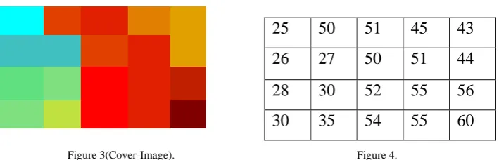
Figure 3(Cover-Image). Figure 4.
Figure-3 image use as Cover-Image .Gray label matrix of that image is shown in figure-4. Secret massage which will embed into Cover-Image is 111100100101100111110110.
Using 3×3 MPPV
For the above secret massage one 3×3 matrix requires which indicating by dark background in figure-5.
Figure 5.Matrix before embedding Figure 6. Matrix after embedding
Image of the above embedded matrix (Figure 6) is in figure 7.
Figure 7.Stego-Image in MPPV Figure 8. Stego-Image in FPPV 6.2 MPPV comparison with FPPV
Using FPPV
For the above secret massage two 3×2 matrix require which indicating by dark background in figure-9.
Figure 9.Matrix before embedding Figure 10.Matrix after embedding
Image of the above embedded matrix (Figure 10) is in figure 8.
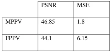
The PSNR block computes the peak signal-to-noise ratio, in decibels, between two images. This ratio is often used as a quality measurement between the original and a compressed image. The higher the PSNR, the better the quality of the compressed, or reconstructed image.The Mean Square Error (MSE) and the Peak Signal to Noise Ratio (PSNR) are the two error metrics used to compare image compression quality. The MSE represents
25 50 51 45 43
26 27 50 51 44
28 30 52 55 56
30 35 54 55 60
25 50 51 45 43
26 27 50 51 44
28 30 52 55 56
30 35 54 55 60
24 55 52 45 43
25 27 49 51 44
28 30 50 55 56
30 35 54 55 60
25 50 51 45 43
27 27 50 51 44
28 30 52 55 56
30 35 54 55 60
25 56 43 45 43
26 27 50 51 44
27 30 56 55 56
the cumulative squared error between the compressed and the original image, whereas PSNR represents a measure of the peak error. The lower the value of MSE, the lower the error.[7]
PSNR=10log10(MAXI 2 / MSE)
Where MAXI is the maximum pixel value. Where, I is the image pixel , K it’s noisy approximation and m×n is
the dimension of the image .
Table-3 showing the PSNR and MSE of the above Cover-Image after embedding secret information 111100100101100111110110 using MPPV and FPPV separately.
Table 3.
6.3 DNA sequence of Stego-Image and MPPV Range Table
Using Methodology-III, mRNA sequence of Stego-Image (Fig-7) is “CUU CCG UGC GAU GUA GCC GGU AUC UUU GGA CAU UGG UAU AUU UCA UGC” which is chosen arbitrarily .Arithmetic encoding convert this mRNA sequence in decimal form is 0.272850788. Equivalent binary form 0. 01000111. This is the compress binary from of Stego-Image.
Range-Table for our example is ( (0,3),(4,7),(8,15),(16,31),(32,63),(64,127,(128,255 )).
Range width of each range are 4, 4, 8,16,32,64,128 respectively.So, range width either 2 or 4 or8 or 16 or 32 or 64 or 128.Equivalent DNA sequence as per Table-1 is CTCTCGCCATAGAC.This DNA sequence converted into binary form 1001100110110101000100110010 by Table-2.
7. Conclusion
This paper hides information in three level depths – First level, embedding the secret information into cover-image, second level, transform the stego-image in DNA sequence and third level compresses the DNA sequence. Degree of security is directly proportional with depth of security.
8. Reference
[1] http://en.wikipedia.org/wiki/Steganography [2] http://dnasequencing.com/DNA.html
[3] Gulve Avinash K and Dr. Mrs. M.S.Joshi ,” A Five Pixel Pair Differencing Algorithm for Compressed Image Steganography with reduced distortion ” , The journal of Systems and Software,2012.
[4] Prof. Samir Kumar Bandyopadhyay and S Chakraborty, “Image Compression using DNA sequence” , International Journal of Computer Science & Engineering Technology , Vol 1, Issue 11, December 2011.
[5] Prof. Samir Kumar Bandyopadhyay and S Chakraborty, “Image Hiding in DNA Sequence Using Arithmetic Encoding”, Journal of Global Research in Computer, Science, Volume 2, No.4, April 2011.
[6] http://www.mathworks.in/help/vision/ref/psnr.html
PSNR MSE
MPPV 46.85 1.8
![Figure-1.[3]](https://thumb-us.123doks.com/thumbv2/123dok_us/9666026.1494466/2.595.195.401.405.507/figure.webp)