National Conference on Advances in Engineering and Applied Science (NCAEAS) 16th February 2017
In association with
I
nternational
Journal
of
Scientific
Research in
Science and
Technology
Performance Improvement of Power System Using Static Synchronous
Compensator (STATCOM)
Priya Naikwad, Mayuri Kalmegh, Poonam Bhonge
Department of Electrical Engineering, RTMNU University, Maharashtra, Nagpur, India
ABSTRACT
STATCOM is a Static synchronous compensator which operates as a shunt connected static var compensator whose both capacitive as well as inductive output current can be controlled by the ac system voltage. STATCOM is one of the key FACTS Controllers. STATCOM is a reactive power source. It gives the voltage support by generating or absorbing capacitors. It normalize the voltage at its terminals by compensating the quantity of reactive power in or out from the power system Reactive power compensation is an important issue in the control of electrical power system. Reactive power increases the transmission system losses and reduces the power transmission capability of the transmission line. Moreover, reactive power flow through the transmission line can cause large amplitude variation in the receiving end voltage. In this paper study the shunt operation of Flexible AC Transmission System (FACT) controller, the Static Synchronous Compensator (STATCOM), & how it helps in the better utilization of a network operating under normal condition. Effect of STATCOM in power system on reactive power control by proper modelling of simple power system and voltage source converter (VSC) based STATCOM using Simulink and simpower toolboxes in MATLAB. It is shown that with suitable control of STATCOM can inject a voltage of required magnitude in shunt with the transmission line. This helps in providing shunt compensation and improving the power flow of transmission line.
Keywords :- STATCOM, FACTS, Power Flow Control, Power System, Modelling of STATCOM.
I.
INTRODUCTION
Modern power systems are highly complex and are expected to fulfill growing demands of power wherever required, with acceptable quality and costs. But in the present scenario control of voltage and reactive power is the major issue in the electrical power transfer. This is because of the topological differences between transmission and distribution system. Reactive power can cause harmful effect on various electrical appliances and motorised applications. This results in reduction of stability margins. This problem can be effectively tackled by the FACTS technology which controls the interrelated parameters of transmission systems including series impedances, shunt impedances, voltage, phase angle, current and damping of oscillations at frequency below the rated frequency.
Although VSCs require self-commutated power semiconductor devices such as GTO, IGBT, IGCT, MCT, etc (with higher costs and losses) unlike in the case of variable impedance type SVC which use thyristor devices, there are many technical advantages of a STATCOM over a SVC such as a) Faster response b) Requires less space as bulky passive components (such as reactors) are eliminated c) Inherently modular and relocatable. Various computing and simulationsof these devices, have found its application to modelling and simulating these devices.
N. G. Hingorani and L. Gyugyi gives The information about all shunt type facts controller design and the basic definition, which define that how the shunt facts controller are differ from the series controller for the compensation of reactive power. Mathur R. Mohan and Rajiv K. Varma in described STATCOM advantages, modes of operation, controller, Analysis of STATCOM, capability characteristics, harmonic performance, losses and modelling of STATCOM.
II.
Static Synchronous Compensator
(STATCOM)
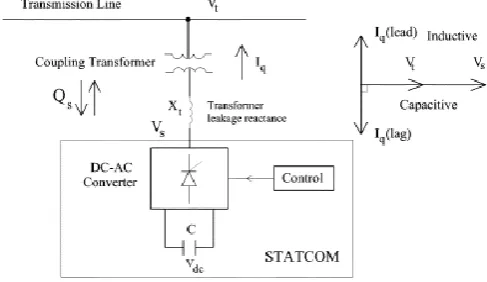
A STATCOM is a static synchronous generator operated as a shunt connected static var Compensator whose capacitive or inductive output current can be controlled independent of the ac system voltage. A STATCOM is a solid state switching converter capable of generating or absorbing independently controllable real and reactive power at its output terminals, when it is fed from an energy source or an energy storage device of appropriate rating. A STATCOM incorporate a voltage source inverter (VSI) that produces a set of three phase ac output voltages, each of which is in phase with, and coupled to the corresponding ac system voltage via a relatively small reactance. This small reactance is usually provided by the per phase leakage reactance of the coupling transformer. The VSI is driven by a dc storage capacitor. By regulating the magnitude of the output voltage produced, the reactive power exchange between STATCOM and the ac system can be controlled. The Static Synchronous Compensator (STATCOM) is a power electronic-based Synchronous Voltage Generator (SVG) that generates a three-phase voltage from a dc capacitor in synchronism with the transmission line voltage and is connected to it by a coupling transformer as shown in Fig.1. By controlling the magnitude of the
STATCOM voltage Vs the reactive power exchange between the STATCOM and the transmission line and hence the amount of shunt compensation can be controlled.
Figure 1.The structure of Static synchronous compensator (STATCOM)
Figure 2 terminal characteristic of STATCOM, respectively. From Fig. 8, STATCOM is a shunt-connected device, which controls the voltage at the connected bus to the reference value by adjusting voltage and angle of internal voltage source.STATCOM exhibits constant current characteristics when the voltage is low/hig under/over the limit. This allows STATCOM to delivers constant reactive power at the limits compared to SVC.
Figure 2. Terminal characteristic of STATCOM
The following mode of operation of STATCOM given as:
1. Over excited mode of operation (Vo ≥ Vbus )
STATCOM to the ac system and the STATCOM generates reactive (capacitive) power for the ac system.
2. Under excited mode of operation (Vo ≤ Vbus ):
On the other hand, if the amplitude of the output voltage is decreased below that of the ac system, then the reactive current flows from the ac system to STATCOM, and the STATCOM absorbs the reactive (inductive) power.
3. Normal (floating) excited mode of operation (Vo = Vbus):
If the output voltage is equal to the ac system voltage, the reactive power exchange is zero. In STATCOM, the resonance phenomenon has been removed. So STATCOM is having more superior performance as compare to SVC.
Io = Where,
Vbus = System voltage Vo = STATCOM voltage Io = Compensating current
Here while compensating of reactive power the phase angle of bus voltage and STATCOM voltage should be same.
2.1 Multi Control Function of STATCOM
In the practical application of a STATCOM, it may be used for controlling one of the following Parameters.
Voltage magnitude of the local bus to which the STATCOM is connected.
Reactive power injection to the local bus, to which the STATCOM is connected.
Impedance of the STATCOM.
. Voltage Injection.
Voltage magnitude at a remote bus.
Power flow.
Apparent power or current control of a local or remote transmission line.
Among these control options, control of the voltage of the local bus which the STATCOM is connected to, is
the most recognized control function. The other control possibilities have not fully been investigated in power flow analysis
III.
NEED OF REACTIVE POWER
COMPENSATION
Voltage control and reactive-power management are two aspects of a single activity that both supports reliability and facilitates commercial transactions across transmission networks. On an alternating-current (AC) power system, voltage is controlled by managing production and absorption of reactive power. Voltage control is complicated by two additional factors. First, the transmission system itself is a non-linear consumer of reactive power, depending upon system loading. At very light loading the system generates reactive power that must be absorbed while at heavy loading the system consumes large amount of reactive power that must be replaced. The systems reactive power requirements also depends on generation and transmission configuration. Consequently, system reactive requirements vary in time as load levels and load and generation patterns change. The bulk-power system is composed of many pieces of equipment, any one of which can fail at any time. Therefore, the system is designed to withstand the loss of any single piece of equipment and to continue operating without impacting any customers. That is, the system is designed to withstand a single contingency. Taken together, these two factors result in a dynamic reactive-power requirement. The loss of a generator or a major transmission line can have the compounding effect of reducing the reactive supply and, at the same time, re configuring flows such that the system is consuming additional reactive power.The need for adjustable reactive power compensation can be divided into three basic classes:
ii) The need to control voltage within acceptable bounds about the desired steady-state value to provide quality service to consumer loads. Following certain abrupt changes in the load, or in the network configuration as a result of switching actions, it may be necessary to make a voltage correction in as short a time as a few cycles of the power frequency. For other voltage disturbances, a correction within a few seconds will suffice. Uncorrected voltage deviations, even if temporary, may lead to an outage or damage to utility or consumer-owned equipment. Even small variations, particularly those that cause flicker, are often objectionable. Reactive power compensation using STATCOM.
iii) The need to regulate voltage profiles in the network to prevent unnecessary flows of reactive power on transmission lines. To this end, reactive power compensation can be used to maintain transmission losses to a practical minimum. While the reactive compensation must be adjusted or changed periodically to maintain minimum losses, the adjustments can be made quite infrequently with several minutes to effect the desired change.
Figure 3. Conventional method of compensation
Show simulation modeled in MATLAB/SIMULINK without STATCOM controlled. SIMULINK is used to model, analyze and simulate dynamic systems using block diagrams. Further, it provides a graphical user interface for constructing block diagram of a system and hence is easy to use. Sim Power Systems libraries of SIMULINK contain models of typical power equipment such as transformers, lines, machines, and power electronics. These models are provide and their validity is based on the experience of the Power Systems the active and reactive power flow in line is same at the
sending end side and receiving end side. The voltage at the load drops due to loss of voltage on lines. This simulation model work at P=203.9KW and Q=200KVAR.
IV.
MODELLING OF STATCOM BY USING
MATLAB/SIMULINK.
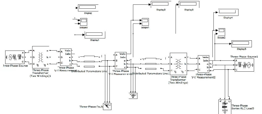
Figure 4.Transmission line without STATCOM / compensation
The sending end and receiving end details for the power system without STATCOM is given in the Table 4.1 and Table 4.2
4.1 Case A: Keeping the active power of the load is constant and varying the reactive power.
Table 4.1. Simulation result without STATCOM for RL load with constant active load power.
Sr N O. Load values P(KW),( QVAR) Ps (K W) Qs (VAR) Vlo ad (K V) Pr (K W) Qr (VA R) 1. 5, 1000 203.
9
200.0* 103
10 .9
4.9 994. 1 2. 5, 500 203.
9
199.6*
10 .9
4.9 497. 1 3. 5, 200 203.
9
199.3*
10 .9
4.9 198. 8 4. 5, 100 203.
9
199.2*
10 .9
4.9 99.4 1
From the Table 4.1, in the first reading, the load is set to absorb 5 KW real and 1000 VARs reactive power at the voltage of 11 KV. It has been observed that the source is supplying real power of 203.9 KW and 200*103. VARs inductive reactive power but the load is consuming 4.9 KW of real power and 994.1 VARs of inductive reactive power. The receiving end voltage has also been reduced
to 10.9 KV from 11 KV. Hence the remaining real and reactive power is absorb by the transmission line. From the above table it is conclude that the receiving end active power is approximately equal to the respective load power with no change in sending and receiving end active power as no active power of the load changed.
Hence Here Ps and Qs represent sending end real and reactive power respectively. Pr and Qr represent receiving end real and reactive power. V load represents RMS voltage across the load.
4.1. Case B : Keeping reactive power of the load is constant and varying the active power.
Table 4.2. Simulation result without STATCOM with constant reactive load power.
Sr N O. Load values P(KW),Q( VAR) Ps (K W) Qs (VAR ) Vl oa (K V) pr (K W ) Qr (VAR)
1. 5, 100 203 .9 199.9 * 10 .9 4. 9 99.41
2. 10, 100 208 .8 199.2 * 10 .9 9. 9 99.41
3. 15, 100 213 .8 199.2 * 10 .9 14 .9 99.41
From the Table 4.2, in the first reading, the load is set to absorb 5 KW real and 100 VARs reactive power at the voltage of 11 KV. It has been observed that the source is supplying real power of 203.9 KW and 199.9*103. VARs inductive reactive power but the load is consuming 4.9 KW of real power and 99.4 VARs of inductive reactive power. The receiving end voltage has also been reduced to 10.9 KV from 11 KV. Hence the remaining real and reactive power is absorb by the transmission line. From the above table it is conclude that the receiving end reactive power is approximately equal to the respective load inductive reactive power with no change in sending and receiving end reactive power for all readings as no reactive power of the load changed. It is also observe that when the load reactive power is reduced, the sending end real and reactive power is reduced and the load real power is increased. Hence Here Ps and Qs represent sending end real and reactive power respectively. Pr and Qr represent receiving end real and reactive power. V load represents RMS voltage across the load.
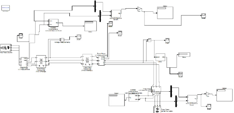
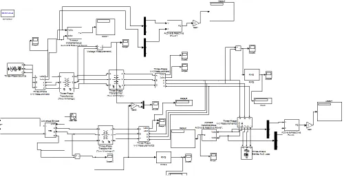
4.2. Transmission line with STATCOM
The effect of STATCOM on the performance of a power system with RL series and RC Load is studied under MATLAB-SIMULINK environment. The real and reactive power flow in the line as well as in the load are
observed without STATCOM. The variations of power flow after the introduction of the STATCOM is noted. A PI-based controller is designed for the STATCOM and then its performance is studied using MATLABSIMULINK. The real and reactive power flow of the models are analyzed. The power flow with the STATCOM is compared with the power system model without connecting STATCOM and thus its performance is evaluated
The modelling of STATCOM with power system is done by using the simpower systems toolboxes in MATLAB /SIMULINK. The modelling is done by connecting a three phase source and RL load through a transmission line. The AC voltage at source is maintained at 11KVand the frequency is 50Hz. The load voltage and phase angles are varied and the real and reactive power flow in the bus are observed. Using the active and the reactive power blocks available in Simpower system, the real and the reactive power flow through the line are measured at both the ends. The MATLAB/Simulink diagram of the power system is shown in Figure The simulink diagram of a power system has AC source, load, transmission line and measurement blocks. The source is of 3 phase, 11KV and 50 Hz AC supply. The load is RL which has 5KW real and 100VAR inductive reactive power at 11KV AC. The transmission line is of 200km length.
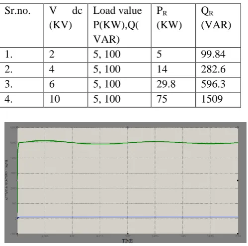
Table 4.3 Simulation result with STATCOM for RL load with constant active and reactive load power.
Sr.no. V dc (KV)
Load value P(KW),Q( VAR)
PR (KW)
QR (VAR)
1. 2 5, 100 5 99.84
2. 4 5, 100 14 282.6
3. 6 5, 100 29.8 596.3
4. 10 5, 100 75 1509
Figure 6. Active and Reactive power at load side
The real and reactive power generated or absorbed by the voltage sourced converter can be controlled independently, provided that the VSC is connected to a DC storage battery, DC voltage source or another VSC instead a DC capacitor. The real power that is being exchanged by the transmission system must be supplied or absorbed at its DC terminals by the DC energy storage or any other previously mentioned device. In contrast, the reactive power exchange is internally generated or absorbed by the VSC without the DC energy storage device. The converter simply interconnects the three-AC Terminals in such a way so that the "reactive"current can flow in either direction. The principle of operation of VSC based STATCOM depends on the control strategy for regulating the interchange of power between the converter/inverter circuit and the grid and it depends also on the output AC voltage of the converter/inverter circuit. If the magnitude of the voltage of the converter is equal to the voltage of the grid . Vsh =Vbus , the interchange of reactive power between the STATCOM and the grid is equal to zero. In contrast, if the voltage of the converter is less than the grid voltage at point of common connection (PCC), Vsh< V bus the STATCOM absorbs reactive power (draws lagging current).
However, if the STATCOM controlled happens to be in such a way that the output voltage of the converter is higher than the grid voltage at PCC, Vsh >Vbus reactive power is injected into the grid. Also, note that the capacity for injecting reactive power into the grid is limited by the maximum voltage and the maximum current allowed by the semiconductors.
B. Restriction of Operation
1. In a STATCOM, the maximum reactive power that can be supplied to the grid depends on the maximum voltage and current permitted by the power semi-conductor, so it s necessary to include the following restriction.The VSC output voltage must fall within the allowed limits of operation:
V sh min≤ V sh≤ Vsh max
Where Vsh max is the maximum voltage rating of the STATCOM .
While V sh min is the minimal voltage limit of the STATCOM.
2. The current flowing through a STATCOM Ish , must be less than the current rating: that is Ish <Ishmax . Where Ishmax is the current rating of the STATCOM converter while Ish is the magnitude of current through the STATCOM and given by
In contrast, it is necessary to include external restriction of the grid voltage at the PCC. According to the specific regulation of the grid operator, the grid voltage at the PCC must be within certain allowed limits. Vbusmin < Vbus <Vbusmax
Figure 7. Output voltage of STATCOM
0 0.005 0.01 0.015 0.02 0.025 0.03 0.035 0.04
0 200 400 600 800 1000 1200
Time
S
ta
tc
o
m
V
o
lt
a
g
Figure 7 shows the output voltage characteristic of STATCOM. A simulink model of the STATCOM based on the VSC is designed. „RL‟ load is connected to the power system. The STATCOM is connected at the load side of the transmission line. The results are taken in the power system model with and without the STATCOM for RL load. The readings are taken for with and without the STATCOM.
V.
CONCLUSION
The STATCOM is a shunt device used in improving the bus voltage profile. It is commonly used to maintain a constant voltage across ac transmission lines and also serve as automatic reactive power control. The MATLAB/SIMULINK environment was used to simulate a model of power system with STATCOM connected to an interconnected power system. The control and performance of STATCOM intended for installation on a transmission line for power quality improvement is presented.
The STATCOM dynamic response is very fast (in millisecond) and able to pass from capacitive mode of operation to an inductive one in a few cycles. When the source voltage decreases, the STATCOM reacts by generatingreactive power, so the DC voltage increases; this is the capacitive mode. On the other hand, when the AC voltage increases, the STATCOM reacts by absorbing the reactive power, so the DC voltage decreased. This is the inductive mode. Simulation results show the effectiveness of STATCOM for regulating bus voltage and control reactive power flow through the line.
VI.
ACKNOWLEDGMENT
The authors would like to thanks Dr. Irfan Ahmed, Anjuman college of engineering and technology MH., India, for their Valuable suggestions regarding for FACTS controllers.
VII.
REFERENCES
[1]. Narain G. Hingorani & Laszlo Gyugyi: „Understanding FACTS: control and technology of flexible AC transmission systems.
[2]. U.A Bakshi & MV Bakshi: „Transmission and distribution