425
Vehicles In Highway Communication System
Using ZigBee And Bluetooth Network
EiThuzarKhin, Chaw Myat New and Hla Myo Tun
Department of Electronic Engineering, Mandalay Technological University, Mandalay [email protected]
Abstract: Globally, many vehicle types operate on the highway system. And highway infrastructure stakeholders have developed a number of products intended to facilitate the identification of critical assets and provide guidance for conductiong security planning. Many of these productsare conducted as joint efforts between the state highway agencies.The main aim of the system is to have a network between Roadside Unit ( RSU ) and On-Board Unit ( OBU ) and between On-Board Unit ( OBU ) and another On-Board Unit ( OBU ). ZigBee is a consortium of software, hardware and services companies having improved a common standard for wireless networking of sensors and microcontrollers.Bluetooth is a technology of wireless standard for exchanging data for short distances. In this article, we point out sending data to the drivers via not only ZigBee module but also Bluetooth module.
Keywords: ZigBee, Bluetooth, PIC 16F877A, Temperature and Humidity Sensor, LCD, Personal Computer
————————————————————
I. Introduction
Vehicles belonging to highway services can announce themselves, automatically informing drivers about overcoming road work areas. Moreover, vehicles change quickly from a mechanical device into a mobile device because these days, our world is becoming increasingly digital and consumers want to remain connected all the time.Vehicles’ drivers should be able to individually set up in their cars the things they want to share. Therefore, Vehicle-to-Roadside Unit communication would revolutionize tomorrow’s driving with the help of intelligent mobility. Moreover, radio-based exchange of information between Vehicles (car to car ) will also be needed in future.
Figure 1. System Configuration of Vehiclesin Highway Security Systmusing ZigBee Network
II. S
YSTEMD
ESIGNThere are three communication parts in the system design; namely, Roadside Unit ( RSU ), On-Board Unit ( OBU ) in which one vehicle is built up with ZigBeemodule and Bluetooth module, and another On-Board Unit ( OBU ) in which one vehicle with Bluetooth module.The RSU is comprised of DHT11 sensor, PIC microcontroller, and ZigBeeCoordinator module. The first OBU consists of ZigBee
Router module, USB to UART IC and Personal Computer having been Bluetooth module, the second OBU having Bluetooth module. Two sensing data from DHT11 are in analog wave form. It is the input data of PIC 16F877A and calibrated digital output waveform is fed into the Transmit ZigBee module. These waveforms are received from the Receive ZigBeemodule which are displayed on the On-Board Unit’s computer monitor-screen. In addition Receive ZigBee module, the PC also has Bluetooth module for re-transmitting the waveforms to other OBU which has Bluetooth module as shown in figure 2.
426
III.
C
OMPONENTSO
FT
HES
YSTEMA.ZigBee
ZigBee, a consortium of software, hardware and services companies developing a common standard, is a wireless network protocol specifically designed for low data rate sensors and control networks. There are three different types of device classes, namely ZigBee routers, ZigBee end devices, and ZigBee coordinator. There are precise steps of how a ZigBee network forms, such as firstly network scanning, then creating a Personal Area Network, discoveries of devices and services, ultimately binding devices. Devices are pre-programmed for their network function. Devices search and discover other devices in the network providing complementary services. Devices can be bound to other devices offering complementary services[2].
Figure 3. Pin Diagram of ZigBee Module ( Xcore 2530 ) B.DHT11 sensor
The DHT11 temperature and humidity sensor is a composite sensor contains a calibrated digital signal output of the temperature and humidity. These are the communication steps of reading the DHT11 data. At first, the environmental temperature and humidity data is tested and recorded after powering on the sensor. Then, microprocessor I/O pin set to output at the same time. Data pin is detected to an external signal of the DHT11 low, the output low of 80 microseconds as the Response signal with the output by the DHT11’s the Data pin 40. After End signal, the DHT11 internally re-test environmental temperature and humidity data and record the data while waiting for the arrival of External signal. The DHT11 uses a simplified single-bus communication. By this way, data for communication and synchronization between the microprocessor and the DHT11 is transmitted as 40 bit, the high pulse first out. Data 40 bit = 8 bit Temperature integer
data + 8 bit Temperature fractional data + 8 bit Humidity integer data + 8 bit Humidity fractional data + 8 it Parity bit
Figure 4.Pin diagram of DHT11 Temperature & Humidity Sensor
Pin 1 = Vdd power supply 3.5 ~ 5.5 V DC Pin 2 = Data serial data, a single bus Pin 3 = NC, empty pin
Pin 4 = Ground pin, negative power
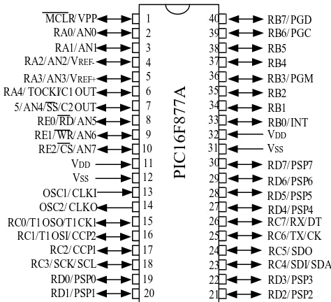
C.PIC 16F877A 1 40 2 39 3 38 4 37 5 36 6 35 7 34 8 33 9 32 10 31 11 30 12 29 13 28 14 27 15 26 16 25 17 24 18 23 19 22 20 21 RD1/ PSP1 RD0/ PSP0 RC3/ SCK/ SCL RC2/ CCP1 RC0/T1 OSO/T1CK1 OSC2/ CLKO OSC1/ CLKI VSS VDD RA4/ TOCKI/C1 OUT
RA3/AN3/VREF+ RA2/AN2/VREF-RA1/AN1 RA0/AN0 MCLR/ VPP 5/AN4/SS/C2 OUT RC1/T1OSI/ CCP2 RE0/RD/AN5 RE1/ WR/AN6 RE2/CS/AN7 RD2/ PSP2 RD3/ PSP3 RC4/ SDI/ SDA RC5/ SDO RC6/TX/CK RC7/RX/DT RD4/ PSP4 RD5/ PSP5 RD6/ PSP6 RD7/ PSP7 VSS VDD RB0/ INT RB1 RB2 RB3/ PGM RB4 RB5 RB6/ PGC RB7/ PGD
P
IC
1
6
F
8
7
7
A
Figure 5. Pin Diagram of PIC 16F877A
The term PIC stood for Peripheral Interface Controller. These devices were originally designed for use in applications with 16-bit microprocessors and computer peripherals, remote control transmitters, domestic products and automotive systems. A simple microcontroller consists of the following modules: an arithmetic logic unit (ALU), one or more working registers for temporary storage during computations, program
427 memory and data memory, program counter, instruction
register, the control unit and a stack[3].
D.Bluetooth
Bluetooth, a wireless technology standard, exchangedata over short distances UHF radio waves in the ISM band from 2.4 GHz to 2.485GHzfrom fixed and mobile devices for the purpose of building Personal Area Networks ( PANs ). Bluetooth is managed by the Bluetooth Special Interest Group ( SIG ). The IEEE standardized Bluetooth as IEEE 802.15.1 with no longer maintenance. Bluetooth uses frequency-hopping spread spectrum radio technology. Bluetooth divides transmitted data into packets on one of 79 designated channels which have every 1 MHz bandwidth where an instantaneous data rate of possible 1 M bits per second[1].
E. USB to UART (Universal Asynchronous Receiver/Transmitter)IC(FT232R)
PCs and many microcontrollers have a component called a UART that handles most of the details of sending and receiving serial data. This serial communication has been set up with 9600 baud rate, one stop bit, seven or eight data bits, one start bit and no parity bit. The FT232R is a USB to serial UART interface with several advanced features. FT232R transfer single chip USB to asynchronous serial data transfer interface. The whole USB protocol is handled on the chip which means no USB specific firmware programming required. 128 byte receive buffer and 256 byte transmit buffer are utilizing buffer smoothing technologies to allow for high data throughput. In this IC, UART interface supports for seven or eight data bits, one or two stop bits and odd/ even/ mark/ space/ no parity. This pre-programmed of unique USB serial number device operates from +3.3V ( using external oscillator) to +5.25V ( internal oscillator ) single power supply. The FT232 is compatible with USB 2.0 full speed, having -40 degree Celsius to +85 degree Celsius extended operating temperature range.
Figure 6. Block Diagram Of FT232
IV.
S
OFTWARED
ESIGNA.Roadside Unit ( RSU )
In the flowchart of RSU, figure 7, the process is started up by initializing the input temperature and humidity data from the sensor. The analog input data from the sensor is fed into the microcontroller and then, the calibrated digital outputs are sent to the transmit ZigBee module ( XCore 2530 ). Since the collection process of sensing data is needed in every second,
there is a yes or no looping for decision making. Ultimately, the results of temperature and humidity data are shown in the LCD display with the unit of Degree Celsius and Percentage.
Figure 7. Flowchart Process Of Roadside Unit ( RSU ) for Vehicles In Highway System Using ZigBee And Bluetooth
Network
428 The Vehicle’s OBU accept the data from the RSU via ZigBee
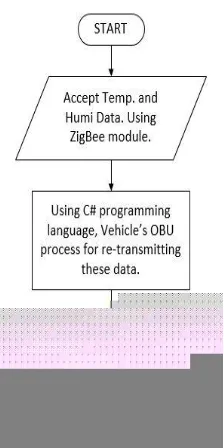
module, and display on the OBU’s monitor-screen,at the first portion. In the second portion, this OBU re-transmit these data to the another OBU using Bluetooth. The process of Temperature and Humidity are displayed in Monitor icon which is illustrated in figure 8.Figure 8.also expresses the connection of Bluetooth and Zigbee modules of the Vehicle’s OBU.
Figure 8.Flowchart Process Of On-Board Unit ( OBU )For Vehicles In Highway System Using ZigBee And Bluetooth
Network
V.
R
ESULTSFigure 9. Constructed Circuit of The Roadside Unit (RSU with ZigBee module)
Figure 10. Constructed Circuit Of On-Board Unit( Vehicle with ZigBee module And Bluetooth module )
Figure 11. Graphical User Interface Of Roadside Unit ( RSU ) Using mikroC Programming Language
429 Figure 12. Constructed Circuit Of On-Board Unit( Vehicle with
ZigBee module )
Figure 13. Graphical User Interface Of On-Board Unit ( OBU ) Using C# Programming Language
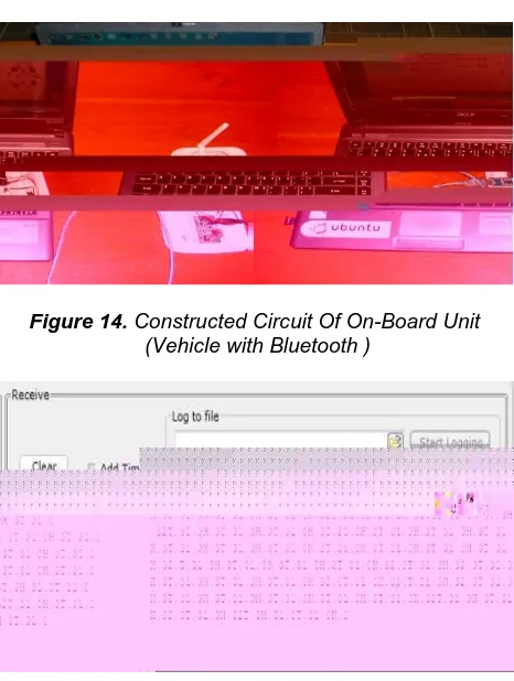
Figure 14. Constructed Circuit Of On-Board Unit (Vehicle with Bluetooth )
Figure 15. Output Result Of UART Terminal Using MikroCProgramming Language of On-Board Unit
The practical construction of On-Board Unit (OBU ) of Vehicles In Highway Security System Using ZigBee Network and Bluetooth Networkand On-Board Unit (OBU) of Vehicles Using Bluetooth Network have been shown in figure 13, figure 14 and figure 15. The numeric value of output Temperature and Humidity data are illustrated in figure 15.
VI.
C
ONCLUSIONThe main aim of this Vehicles in Highways System is to have communication links along the highway lane.In future, vehicles (cars) will become connected, enabling the exchange of information between OBU and OBU (Vehicles-to-Vehicles) and their environment through Internet connection. With the help of RSU, the new era of mobility will lead to a highway for companies and countries in dealing with differerent challenges, such as security aspects, data privacy, and consistent connection line. According to market analysis, one in every five cars will be connected through the Internet until 2020 for the purpose of cooperation.
A
CKNOWLEDGMENTI wish to express my deepest gratitude to Dr.HlaMyoTun, Associate Professor and Head of the Department of Electronic Engineering, Mandalay Technological University for his kind help and encouragement. And I am also especially grateful to the supervisor, Dr.ChawMyatNwe, Associate Professor, Department of Electronic Engineering, Mandalay Technological University for her valuable teaching and ideas throughout this work. I would like to thank a lot to all my teachers and friends from the Department of Electronic Engineering, Mandalay Technological University.
R
EFERENCES[1] “Bluetooth traveler”, hoovers.com, 9 April 2010.
[2] “Development Of Alert Security Home System Using ZigBee Technology ”,UniversitiTeknologi Malaysia, 2013.
[3] “Design Of Wireless Home And Security System Using PIC microcontroller”,M.E Embedded System Technology, Anna University, India, 2013.
[4] “Newton’s telecom dictionary. New York ”, Flatiron Publishing, 2007.
[5] “ Vehicle Security At Highway Using Intelligent Vehicle
Highway System ( IVHS