© 2018 IJSRST | Volume 4 | Issue 2 | Print ISSN: 2395-6011 | Online ISSN: 2395-602X Themed Section: Science and Technology
A Novel Step-Up Multi-input DC–DC Converter for Grid Connected and HEV
Application
Dr. N. Samba Siva Rao1, M. Rakesh2
1Professor, Department of Electrical & Electronics Engineering, NRI Institute of Technology, Agiripalli, Andhra
Pradesh, India
2PG Scholar, Department of Electrical & Electronics Engineering, NRI Institute of Technology, Agiripalli,
Andhra Pradesh, India
ABSTRACT
A multi-input dc–dc converter is proposed and studied for hybrid electric vehicles. Compared to conventional works, the output gain is increased. Fuel cell (FC), photovoltaic panel, and energy storage system are the input sources for the proposed converter. The FC is considered as the main power supply, and roof-top PV is employed to charge the battery, increase the efficiency, and reduce fuel economy. The converter has the capability of providing the demanded power by load in absence of one or two resources. Moreover, the power management strategy is described and applied in a control method. Also the proposed concept not only for HEV and also we can use these type of systems for grid connected systems using separate converter. The overall system is designed and simulated using MATLAB/SIMULINK software.
Keywords : Hybrid Electric Vehicle (HEV), Multi-Input Converter, Power Management.
I.
INTRODUCTION
Global warming and lack of fossil fuels are the main drawbacks of vehicles powered by oil or diesel. In order to overcome the aforementioned problems and regarding the potential of clean energies in producing electricity, car designers have shown interest in hybrid electric vehicles (HEVs) and plug-in hybrid electric vehicles. The overall structure of HEV powered by renewable resources is depicted in Figure 1. Electric vehicles (EVs) have also been studied. EVs rely on energy stored in energy storage system (ESS) [1]. Limited driving range and long battery charging time are their main drawbacks. However, by using a bidirectional on/off board charger, they could have the V2G capability. Solar-assisted EVs have also been studied. Required location and size of PV panels have made them impractical at present [2]. Employing fuel cell as the main power source of HEVs is the result of many years of research and development on HEVs. Pure water and heat are the only emissions of fuel
cells. Furthermore, FCs have other advantages like high density output current ability, clean electricity generation, and high-efficiency operation [3].
However, the great number of power switches could reduce the reliability and increase the cost. In [7], a multi input dc–dc boost converter for hybrid PV/FC/Battery is proposed, but the proposed converter cannot work properly because the battery can be only discharged by PV and only charged by FC. In [8], a two-input dc–dc converter is proposed to interface two power sources with a dc bus or load. The converter has high efficiency due to achieving turn-on zero voltage switching of all switches. However, it lacks a bidirectional port. Hence, in applications in need of ESS, it cannot be used. A compact two-input converter is proposed for standalone PV systems in [9]. Moreover, high voltage gain of the converter makes the converter suitable for low-input voltage applications. However, the high number of semiconductors and passive elements reduce the efficiency. Control method preset in the vehicle’s controller should control the power flow between renewable resources, battery unit, and electrical motor. Optimal utilization of power resources, providing demand power permanently, operating fuel cell, and PV panel in their optimum region are the main duties of control scheme. Some converters have been proposed recently for PVs systems [10]–[12], but the required converter for HEV applications should extract power from PV and FC. Besides, in order to supply back-up power from the battery, a bidirectional port is needed to charge and discharge the battery according to discrepancy between generated power and demanded energy [13], [14]. A multi input converter can provide power to the load from different energy sources simultaneously or individually. In the literature, several attempts have been done to get the task done [15]–[19]. An attempt has been done in [20], in which an intelligent optimal power management was introduced. The scheme has three main advances including control of temperature fan, fuzzy hydrogen control, and adaptive current– voltage fast-charging control. In [21], a two-layer energy management has been studied. Minimizing hydrogen consumption is the objective of this study.
Due to the fact that initial cost of PVs is high and in order to increase the extracted power from the PV panels, MPPT made between different MPPT techniques with respect to tracking factor, dynamic response, PV voltage ripple, and use of sensors. The other way to improve the efficiency is to enhance the efficiency of the electric components [23]. In this study, a novel three-input dc–dc converter is proposed to merge a PV, a fuel cell, and a battery and connect them to the grid. Furthermore, dc gain is enhanced in respect of conventional converters. Meanwhile, MPPT can be obtained for PV. The battery can be charged and discharged in order to achieve power management. In the following two sections, the proposed structure is studied and different operation modes are discussed. In Section IV, the converter is modeled and linearized to control the converter.
Figure 1. General Structure of the multi powered HEV.
II.
PROPOSED CONVERTER TOPOLOGY
resistance, respectively. RLoad is the equivalent resistance of loads connected to the dc bus. S1, S2, S3 , and S4 are power switches. DiodesD1, D2,D3 , andD4 are used to establish modes, which will be described. Capacitor C1 is used to increase output gain and output capacitor Co is performed as an output voltage filter. System is operating in continuous-conduct mode to produce smooth current with least possible amount of current ripple.
Figure 2. Three-input dc–dc boost converter.
III.
OPERATION MODES
In this section, principles of the proposed converter are discussed. Operation of the converter is divided into three states:
1. The load is supplied by PV and FC and battery is not used.
2. The load is supplied by PV, FC, and battery, in this state, battery is in discharging mode.
3. The load is supplied by PV and FC and battery is in charging mode.
A. First Operation State (the Load is supplied by PV and FC While Battery is not used)
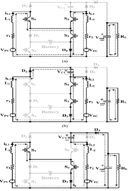
In this state, as it is illustrated in Figure 3, there are three operation modes. During this state, the system is operating without battery charging or discharging. Therefore, there are two paths for current to flow (through S3 and D3 or D1 and S4 ). In this paper, S3 and D3 is considered as common path. However, D1 and S4 could be chosen as an alternative path. During
this state, switch S3 is permanently ON and switch S4 is OFF.
Mode 1: (0< t <d1T): In this interval, switches S1, S2, S3, and diode D3 are turned ON. Inductors L1 and L2 are charged via power sources vPV and vF C , respectively [see Figure 3(a)].
Mode 2: (d1T < t < d2T): In this interval, switch S1 is turned OFF and D2 is turned ON and S2, S3 , and D3 are Still ON. Inductor L2 is still charged and inductor L1 is being discharged via VPC − VF C [see Figure 3(b)].
Mode 3: (d2T < t < T): In this interval, S1 is turned ON and S2 is turned OFF and S3 and D3 are still ON. Inductor L1 is charged with vPV and inductor L2 is discharged via VPV + VC1 − Vo [see Figure 3(c)].
Figure 3. Current-flow path of operating modes in first operating state.
B. Second Operation State (the Load is Supplied by PV, FC, and Battery)
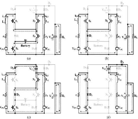
In this state, as it is illustrated in Figure 4, there are four operation modes. During this state, the load is supplied by all input sources (PV, FC, and battery). In first mode, there is only one current path. However, in other three modes, there are two current paths (through S3 and D3 or D1 and S4 ). In this state, current flows through D1 and S4 . Switch S4 is permanently ON during this state.
Mode 1: (0 < t < d1T): In this interval, S1, S2, S3 , and S4 are turned ON. Inductors L1 and L2 are charged by VPV + vBattery and VF C + vBattery , respectively [see Figure 4(a)].
Mode 2: (d1T < t < d2T): In this interval, S1, S2, S4 , And D1 are turned ON. Inductors L1 and L2 are charged by VPV and VF C , respectively [see Figure 4(b)].
Mode 3: (d2 T < t < d3T): In this interval, S2, S4,D1 ,and D2 are turned ON. Inductor L1 is
discharged to capacitor C1 and L2 is charged by vF C [see Figure 4(c)].
Mode 4: (d3T < t < d4T): In this interval, S1,
S4,D1 ,and D4 are turned ON. Inductor L1 is charged by VPV
and inductor L2 discharges C1 to the output capacitor [see Figure 4(d)].
Figure 4. Current-flow paths in different operation modes of second state. (a) Mode 1. (b) Mode 2. (c)
Mode 3. (d) Mode 4.
C. Third Operation State (the Load is Supplied by PV and FC While Battery is in Charging Mode)
In this state, as it is illustrated in Figure 5, there are four modes. During this state, PV and FC charges the battery and supply the energy of load. In the first- and second-operation modes, there are two possible current paths through S3 and D3 or D1 and S4 ). The path D1 and S4 is chosen to flow the current in this state. During this state, switch S3 is permanently OFF and diode D1 conducts.
Mode 1: (0 < t < d1T): In this interval, S1, S2, S4 , and D1 are turned ON. Inductors L1 and L2 are charged by vPV and vF C , respectively [see Figure 5(a)].
Mode 2: (d1T < t < d2T): In this interval, S2, S4 , and D1 are turned ON. Inductor L1 is discharged to capacitor C1 and inductor L2 is charged by vF C [see Figure 5(b)].
Mode 4: (d3 T < t < d4T): In this interval, S1, S4,D1 , and D4 are turned ON. Inductor L1 is charged by vPV − vBattery and inductor L2 is discharged by vF C − vC1 − vo [see Figure 5(d)].
Figure 5. Current-flow path of operating modes in third operating state. (a) Mode 1. (b) Mode 2. (c) Mode
3. (d) Mode 4.
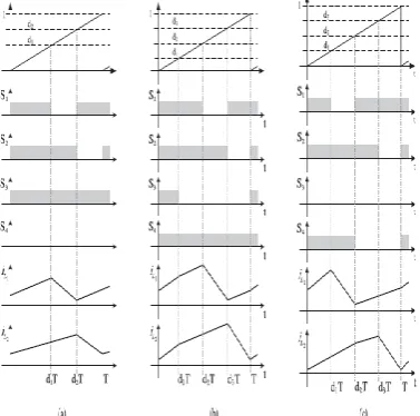
Figure 6. Switching pattern for three states. (a) First state. (b) Second state. (c) Third state.
IV.
GRID CONNECTED INVERTER
A connected photovoltaic power system, or
grid-connected PV system is
an electricity generating system that is connected to the utility grid. A grid-connected PV system consists of solar panels, one or several inverters, a power conditioning unit and grid connection equipment.
They range from small residential and
commercial rooftop systems to large utility-scale solar power stations. Unlike stand-alone power systems, a grid-connected system rarely includes an integrated battery solution, as they are still very expensive. When conditions are right, the grid-connected PV
system supplies the excess power, beyond
consumption by the connected load.
While synchronizing a DG with a utility grid it shall not cause a voltage fluctuation of more than ± 5% of the existing voltage level at the Point of Common Coupling (PCC). The allowable voltage harmonic distortion is specified at the PCC. It is normally required that the maximum voltage total harmonic distortion is 5% and maximum individual frequency voltage harmonic is 3% of the fundamental component.
V.
SIMULATION RESULTS
Figure 7. shows the Matlab/Simulink model of proposed three input DC-DC converter
Figure 8. shows the switch voltages S1,S2,S3 and S4
Figure 9. shows the Inductor Currents of L1 and L2
Figure 10. shows the output voltage of the proposed converter and voltage across capacitor
Figure 11. shows the battery discharging mode
Figure 12. shows the battery charging mode
Figure 13. shows the Matlab/Simulink model of proposed three input DC-DC converter applied to
grid-tied inverter system
VI.
CONCLUSION
In this study, a novel three-input dc/dc converter is proposed and analyzed thoroughly. The converter has the capability of providing the demanded power by load in absence of one or two resources. The promising performance of the converter and employed control method offer a high reliability for utilizing the converter in industrial and domestic applications. The converter is modeled for three different operational states and simulated. The topic further implemented with grid-tied inverter to synchronize PV with grid using PLL logic. The results are shown that grid current is having less tolerance
of THD. The total study is simulated using
Matlab/Simulink and results are observed.
VII.
REFERENCES
[1]. A. Ostadi and M. Kazerani, "Optimal sizing of the battery unit in a plug-in electric vehicle," IEEE Trans. Veh. Technol., vol. 63, no. 7, pp. 3077–3084, Sep. 2014.
[2]. P. Mulhall, S. M. Lukic, S. G. Wirashingha, Y.-J. Lee, and A. Emadi, "Solar-assisted electric auto rickshaw three-wheeler," IEEE Trans. Veh. Technol., vol. 59, no. 5, pp. 2298—2307, Jun. 2010.
[3]. H. J. Chiu and L. W. Lin, "A bidirectional dc-dc converter for fuel cell electric vehicle driving system," IEEE Trans. Power Electron., vol. 21, no. 4, pp. 950–958, Jul. 2006.
[4]. T. Markel, M. Zolot, K. B. Wipke, and A. A. Pesaran, "Energy storage requirements for hybrid fuel cell vehicles," presented at the Adv. Autom. Battery Conf., Nice, France, 2003. [5]. S.Miaosen, "Z-source inverter design, analysis,
and its application in fuel cell vehicles," Ph.D. dissertation, Dept. Electr. Comput. Eng., Michigan State Univ., East Lansing, MI, USA, 2007.
[6]. O. Hegazy, R. Barrero, J. Van Mierlo, P. Lataire, N. Omar, and T. Coosemans, "An advanced power electronics interface for electric vehicles applications," IEEE Trans. Power Electron., vol. 28, no. 12, pp. 1–14, Dec. 2013.
[7]. M. R. Feyzi, S. A. KH. Mozaffari Niapour, F. Nejabatkhah, S. Danyali, and A. Feizi, "Brushless DC motor drive based on multi-input DC boost converter supplemented hybrid PV/FC/Battery power system," in Proc. IEEE Electr. Comput. Eng. Conf., 2011, pp. 000442–000446.
[8]. R. J. Wai, C. Y. Lin, and B. H. Chen, "High-efficiency DC–DC converter with two input power sources," IEEE Trans. Power Electron., vol. 27, no. 4, pp. 1862–1875, Apr. 2012.
[9]. L. J. Chien, C. C. Chen, J. F. Chen, and Y. P. Hsieh, "Novel three-port converter with high-voltage gain," IEEE Trans. Power Electron., vol. 29, no. 9, pp. 4693–4703, Sep. 2014.
[10]. R. B. Mohammad, H. Ardi, R. Alizadeh, and A.