Design and Fabrication of High Frequency
Linear Function Generator with Digital
Frequency Counter using MAX038 and a PIC
microcontroller
P. KanakaRaju1 and M. PurnaChandra Rao2
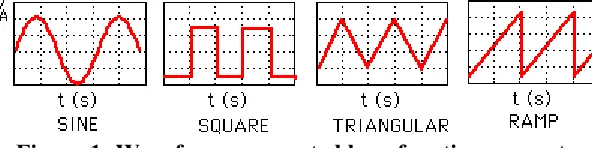
Introduction: function generator is a versatile instrument, extensively used in electronics, mechanics, bioengineering, physics and many other fields. It generates a wide variety of electrical signals and waveforms for testing and diagnostic applications. Figure 1 shows the most common waveforms generated by a function generator. Many of the comprehensive function generators are able to operate at much higher frequencies: 1Hz to 20MHz.
Figure 1: Waveforms generated by a function generator
There are many ways of designing function generator circuits, however there are two main approaches:
Analogue function generator: It utilize analogue technology and offer a number of
advantages:
1. Cost effective: Analog function generators are very cost effective, being at the lower end
of the function generator price range.
2. Simple to use: Analog function generators provide an effective test instrument that is
able to meet most user needs.
1
Department of Electronics and Physics, GIS, GITAM University, Visakhapatnam, INDIA
2
Department of System Design, Andhra University, Visakhapatnam, INDIA
DOI: http://dx.doi.org/10.21172/1.73.536
e-ISSN:2278-621X
Abstract — The main process of this research is to design and fabricate an extremely low cost,
small sized, accurate and versatile function generator up to 17MHz with frequency resolution of 1 Hz by using minimum components like IC MAX038- analog function generator along with digital frequency counter implemented by PIC16F876 microcontroller and 2×16 characters LCD. External amplitude/duty cycle is controlled by ICs LT1364[1] and NE5532N[2], with the following key features: 1Hz to 17MHz operating frequency range, sine, square and triangular waveforms, independent frequency and duty-cycle adjustments, 15% to 85% variable duty cycle along with 50% fixed duty cycle, low-impedance output buffer, low temperature drift. In this research, the complete design of the function generator is provided. Hardware and software technologies are integrated to fabricate this instrument.
3. Maximum frequencies: The analog function generators do not have the high frequency
limitations on non-sinusoidal waveforms such as triangles and ramps as do the digital function generator.
Digital function generator: It utilizes digital technology to generate the waveforms, such as
Direct Digital Synthesis [6]. DDS uses a phase accumulator, a look-up table containing a digital representation of the waveform, and a DAC [8]. These are able to offer high levels of accuracy and stability, but the disadvantage is that they are more comprehensive than analogue cousins; they require a high performance DAC and other digital circuitry which are costly and also complicated.
This research work mainly deals with the design and fabrication of analog function generator with IC MAX038.
Description:
MAX038: IC MAX038 is a frequency, precision function generator producing
high-frequency triangle, sawtooth, sine, square, and pulse waveforms with a minimum of external components. The output frequency can be controlled over a frequency range of 0.1Hz to 20MHz [3] by an internal 2.5V band gap voltage reference and an external resistor and a capacitor. The duty cycle can be varied over a wide range by applying a ±2.3V control signal, facilitating pulse-width modulation and the generation of sawtooth waveforms. Frequency modulation and frequency sweeping can also be achieved. The duty cycle and frequency controls are independent. Sine, square, or triangle waveforms can be selected at the output by setting the appropriate code at two TTL-compatible select pins. The output signal for all waveforms is a 2VP-P signal that is symmetrical around ground. The low-impedance output can drive up to ±20mA. The TTL-compatible SYNC output from the internal oscillator maintains a 50% duty cycle regardless of the duty cycle of the other waveforms to synchronize other devices in the system.
PIC16F876: The PIC16F876 is a high performance RISC CPU [4] with 35 single word instructions, CMOS FLASH-based 8-bit microcontroller packs Microchip's powerful PIC® architecture in 28-pin package. Features: 256 bytes of EEPROM data memory, self programming, an ICD, 5 channels of 10-bit Analog-to-Digital (A/D) converter, 2 additional timers, 2 capture/compare/PWM functions, the synchronous serial port can be configured as either 3-wire Serial Peripheral Interface (SPI™) or the 2-wire Inter-Integrated Circuit (I²C™) bus and a Universal Asynchronous Receiver Transmitter (USART). All of these features make it ideal for more advanced level A/D applications in automotive, industrial, appliances and consumer applications.
2c. Basic circuit of sine wave output with 50% duty cycle
Design and Fabrication: MAX038 is a relaxation oscillator, operates by alternately charging and
discharging a capacitor, with constant currents. Basically it is a dual slope integrator that simultaneously produces a triangular and a square wave (TTL). The frequency is determined by the external oscillator capacitor and the current flowing into IIN. This triangular wave is applied to an internal comparator, in order to make a square wave. By applying the triangular wave to a waveform shaping circuit, it produces a sine wave with constant amplitude[5]. The triangle, square, and sine waves are input to a multiplexer that selects the type of wave which is applied to the low impedance separating amplifier [7]. Figure 3 and 4 shows the block diagram and the circuit diagram of the function generator respectively.
Figure: 4 Circuit diagram of the function generator
Figure: 6 complete function generator with front panel controls
As shown in figure 6, the frequency range can be selected by placing different capacitors to the COSC input of MAX038 by using a twelve position rotary switch. The output frequency can be selected within the frequency range by a potentiometer [8] for the fine tuning. The DADJ input of MAX038 controls the duty cycle of the waveform. By using a switch, it is possible to either enable or disable the 50% fixed duty cycle. If enabled, the duty cycle can be adjusted by a potentiometer. The type of output waveform can be selected from a "FUNCTION" switch which is a 3-position rotary switch. The common of the switch is driven HIGH, while the two inputs of MAX038- A0 and A1 are pulled LOW with 10K resistors. When both inputs A0 and A1 are '0': the output is square wave, when A0 is '1' and A1 is '0': the output is triangular waveform and when A1 is '1' and A0 is '0': the output is sine wave. The output is buffered with LT1364 operational amplifier that can linearly amplify the waveform up to 5Vpp. The peak to peak amplitude is also controlled a potentiometer. By default, the output waveform is symmetrical to the ground. DC offset can be added to the output by a switch "DC OFFSET ". The DC offset is also controlled by a potentiometer. Finally the output is connected to a BNC connector for external use.
the figure, CRO shows the type of the waveform selected and multimeter shows the frequency in KHz that matches with function generator’s LCD display in terms of Hz.
7a. Function generator at a frequency of 1hz
(sinusoidally oscillating dot on the CRO screen)
Multimeter shows 0.001KHz, LCD shows 1Hz
7b. Function generator at a frequency of 147 hz (Function: square wave on the CRO screen) Multimeter shows 0.147KHz, LCD shows 147Hz
7c. Function generator at a frequency of 1Khz (Function: sinusoidal wave on the CRO screen)
Multimeter shows 1.000 KHz, LCD shows 1000 Hz
7d. Function generator at a frequency of 10.68 Khz
(Function: square wave with variable duty cycle on the CRO screen)
7e. Function generator at a frequency of 1Mhz (Function: sinusoidal wave on the CRO screen)
Multimeter shows 1000 KHz, LCD shows 1000008 Hz
7f. Function generator at a frequency of 17.38Mhz
(Function: sinusoidal wave on the CRO screen) LCD shows 17 337 153 Hz
Below graph shows a plot of obtained frequency {log (of)} compared with the standard frequency {log (sf)} at 15 events, both are tracking each other. Thus the designed function generator working with almost nil error.
0 2 4 6 8 10 12 14 16 18
-1 0 1 2 3 4 5 6 7 8 Standred Frequency Obtained frequency
Number of events
log (sf ) -1 0 1 2 3 4 5 6 7 8 log (of )
Conclusion: This paper describes the design and fabrication of low cost function generator useful for research and educational purpose. It is very easy to operate between the desired frequency and amplitude. The front panel controls are user friendly. Experimental results showed that the signal generator is of high precision, small size, and convenient and stable in use However, when the output frequency increases to 10 MHz, the amplitude begins to decay due to bandwidth limitations of the ic LT1364. Further improvements are needed.
References
[1] http://cds.linear.com/docs/en/datasheet/13645fa.pdf
[2] https://www.fairchildsemi.com/datasheets/NE/NE5532.pdf [3] http://pdfserv.maximintegrated.com/en/ds/MAX038.pdf
[4] http://microrato.ua.pt/main/Actividades/Estagios/docs/pic16f87x.pdf
[5] C. F. Coombs, "Electronic Instrument Handbook," McGraw-Hill, Inc., New York, 1995.
[6] Jian Qi,1 Qun Sun,1 Xiaoliang Wu,2 Chong Wang,1 and Linlin Chen1, “Design and Analysis of a Low Cost Wave Generator Based on Direct Digital Synthesis”.
[7] Xian Qin Han, Xiang Lei Zhu, “Multi-Signal Generator Design”.
[8] Patrick O. Olabisi1, B. J. Olufeagba2, “Step-Wise Approximation Technique in the Design of a Function Generator”.