Characterisation of a fibronectin material for application in tissue
engineering
A thesis submitted to the University o f London for the degree o f Doctor of Philosophy in the Faculty of Science
by
Sarah lone Harding BSc (Hons) MRes
Department o f Biochemical Engineering and the Department of Plastic Surgery
University College London
ProQuest Number: 10014316
All rights reserved
INFORMATION TO ALL USERS
The quality of this reproduction is dependent upon the quality of the copy submitted.
In the unlikely event that the author did not send a complete manuscript and there are missing pages, these will be noted. Also, if material had to be removed,
a note will indicate the deletion.
uest.
ProQuest 10014316
Published by ProQuest LLC(2016). Copyright of the Dissertation is held by the Author.
All rights reserved.
This work is protected against unauthorized copying under Title 17, United States Code. Microform Edition © ProQuest LLC.
ProQuest LLC
789 East Eisenhower Parkway P.O. Box 1346
Acknowledgements
I would like to thank my supervisor Professor Peter Dunnill for his support and enthusiasm over the years. I would also like to thank Dr Robert Brown for his support and advice.
Abstract
The repair o f damaged human tissue may be enhanced greatly by a capacity to organise the arrangement of the healing cells. This study has demonstrated an approach to quantifying the capacity o f fibronectin cables to align human cells. It is based on the staining and subsequent image analysis o f cells in the neighbourhood of the cables, and the application o f an orientation index (S) to give a quantitative measure of cell alignment to the cables.
The lateral extent of cell alignment ie. the number of cell layers lined up beside a cable, termed the “cell docking band width”, was independent of cable diameter. Scanning electron microscopy confirmed cell alignment and the deposition o f fine fibrils by the cells. Orientation of cells to different cable configurations, as measured by an orientation index (S), ranged between 0.96 - 0.97 in the cell docking band width, denoting almost perfect alignment. Aligned cell docking band widths increased as a function of initial cell seeding level. This method represents a functional test system for fibronectin as a contact guidance material.
Following atherosclerotic plaque formation in coronary artery, a bypass operation is sometimes necessary, normally utilising autologous vein transferal. Such grafts are subject to failure and a tissue engineered vascular graft is highly sought after. Fibronectin tubes in spiral orientation, produced by a hand winding method, allowed for close control of tube size dimensions. The tubes had a maximum tensile strength o f lON/mm^ (at 34% RH) which decreased with increasing relative humidity. Tube burst pressure was 187mmHg (24.6x10'^ N/mm^) thus exceeding capillary, venule, and vena cava systemic blood pressure. The reservations on clinical use are discussed. Endothelial cell attachment was supported within the hollow core o f the tube, and seen by S.E.M.
CONTENTS
Title of thesis ... 1
Acknowledgements... 2
Abstract ... 3
Contents ... 4
List of Figures ... 1 1 List of Tables ... 16
Publications ... 17
Abstracts for conference ... 17
Section 1. Introduction ... 18
1.1 Overview - Tissue Engineering ... 18
1.2 Fibronectin (Fn) and Fibrinogen (Fgn) - provisional w o u n d 18 healing matrix proteins 1.2.1 Fibrinogen ... 19
1.2.1.1 The role of fibrinogen in blood clotting ... 20
1.2.2 Fibronectin ... 20
1.2.2.1 Soluble and insoluble fibronectin... 22
1.2.2.2 Fibronectin localisation ... 23
1.2.2.3 Fibronectin gene structure ... 23
1.2.2.4 Functional associations of fibronectin ... 24
1.2 Skin 24 1.3.1 The epidermis, dermis, and hypodermis ... 27
1.3.2 Dermal wound healing... 27
1.4 Bloodvessels ... 1.4.1 Vascular endothelium ... 3 j
1.4.2 Coronary atherosclerosis and thrombosis ... 32
1.4.3 Blood vessel grafting... 3 4 1.5 Fibronectin source and preliminary fibronectin c a b le ... 35
preparation 1. 6 Aims o f the study ... 38
Section 2. Materials and methods... 39
2.1 Fibronectinmaterial preparation and characterisation ... 39
2.1.1 Fibronectin material preparation ... 39
2.1.2 Total protein assay ... 40
2.1.3 Fibronectin and fibrinogen assay ... 40
2.2 Scanning electron microscopy (S.E.M) ... 41
2.3 Fibronectin cable preparation ... 41
2.3.1 Drawn fibronectin cable preparation ... 41
2.3.2 Hand spun fibronectin cable preparation ... 42
2.5 Mechanical testing o f fibronectin tubes ... 47
2.5.1 Tensile tests of freeze dried tubes ... 47
2.5.2 Tensile tests of fully hydrated tubes ... 48
2.5.3 Burst pressure ... 48
2.6 Fibronectin cable characterisation ... 2.6.1 Polarisation microscopy and S.E.M. to determ ine 49 fibronectin cable and tube orientation 2.6.1.1 Polarisation microscopy ... 49
2.6.1.2 Fibronectin tube orientation viewed by S .E .M ... 50
2.6.2 Hygroscopic properties of fibronectin cable ... 50
2.6.3 Coagulation time versus cable structure in ... 50
cross section 2.6.4 Coagulation time versus cable tensile strength... 51
2.6.5 Dehydration method versus cable tensile strength... 51
2.7 Cable de-acidification ... 51
2.8 Primary cell culture... 52
2.8.1 Human dermal fibroblasts (HDFs) ... 52
2.8.2 Endothelial cells ... 53
2.8.2.1 Human umbilical vein endothelial cells (HUVECs) - - 53
2.8.2.2 Human microvascular endothelial cells -adult ... 54
-(HMVECA) 2.8.2.3 Pig aorta endothelial cells (PAEs) ... 54
2.9 Alignment function testing ofsingle cables o f fibronectin... 55
2.9.1 Alignment testing of HDFs around fibronectin cable 55 2.9.2 Alignment testing of HDFs around hand spun ... 55
hand spun cable
2A0 Image analysis ... 56
2.10.1 Human dermal fibroblast alignment to fibronectin cable - - 56 2.10.2 Orientation index (S) quantitation of HDF alignm ent 57 to fibronectin cable
2.11 Scanning electron microscopy and time lapse studies fo r e a r ly 57 association o f cells to fibronectin cable
2.11.1 S.E.M ... 58 2.11.2 Time lapse photography image analysis ... 58
2.12 Fibronectin tube in vitro cell culture ... 59
2.13 Cell attachment and proliferation on fibronectin and other materials 61 2.13.1 Immunofluorescence staining of cell adhesion plaques - - - 61 to establish cell attachment to fibronectin
2.13.2 Cell proliferation assay ... 61 2.13.2.1 MTT standard curve for HDFs in suspension ... 62 2.13.2.2 Measurement of cell proliferation on fibronectin and ... 62 other materials
Section 3. Results and Discussion... 64
3.1 Human dermal fibroblast (HDF) alignment to fibronectin cable in 64 culture
3.1.1 Human dermal fibroblast alignment to fibronectin cable - - 65 viewed by light microscopy and S.E.M.
3.1.2.1 Contact guidance and chemotaxis 75 ' 3.1.2.2 Control alignment to glass etchings and the role of ... 75
topography
3.1.2.3 Tris buffer treatment of fibronectin cables ... 76 3.1.2.4 Cell migration quantitation by time lapse image ... 76
analysis
3.1.3 Spacing between cells in aligned cell layers by Fn ... 78 3.1.4 Cell docking band width vs. the Fn cable width ... 81 3.1.5 The Orientation Index (S) value of cell alignment to Fn ... 82 in the cell docking band width
3.1.6 Orientation Index (S) value vs. the cell docking band width - - 84 3.1.7 Cues for cell alignment ... 85 3.1.8 Cellular response to external stimuli ... 8 6
3.1.9 Fibronectin cable width in application ... 87
3.2 Cell migration, attachment, and proliferation on fibronectin cable; . .. 8 8
and spun Fn cable characterisation
3.2.1 Cell attachment to Fn cable in the first few hours ... 89 of culture - S.E.M study
3.2.2.1 Time lapse image analysis ... 91 3.2.2.2 Cell migration velocity vs. cell distance from the F n 93 cable
3.2.3 Immunofluorescence staining to highlight cell attachment .. 94 plaques
3.2.4 Quantitation of cell proliferation on Fn and other materials .. 95 3.2.5 Coagulation time vs. the tensile strength o f hand spun Fn . .. 99 cable
3.2.6 Fn cable coagulation time vs. cable structure in cross... 101 section
3.2.7.1 Cell culture on ethanol/acetone dried cables ... 102
3.2.7 2 Structure of ethanol/acetone dried cables by S.E.M ... 103
3.2.8 Fibronectin tube orientation viewed by polarisation ... 106
microscopy 3.2.9 Fibronectin tube orientation viewed by S.E.M ... 108
3.2.10 Hygroscopic properties of Fn cable ... 110
3.2.11 Process implications ... I l l 3.3 Fibronectin tubes ... 112
3.3.1 The freeze dried fibronectin tube ... 113
3.3.2 Tensile tests ... 114
3.3.3 Burst pressure ... 116
3.3.4 Endothelial cell culture in the fibronectin tube lumen ... 119
4.0 General discussion... 122
4.0 Wound repair and scar reduction ... 122
4.1.1 Fibronectin cable use ... 122
4.1.1.1 Collagen orientation via fibroblasts ... 122
4.1.1.2 Skin regeneration ... 123
4.1.1.3 Scar reduction by fibronectin cables ... 123
4.1.2 Accessories - cell populations ... 124
4.1.3 Adhesions and the control of inflammation via fibronectin 125 4.1.4 Dressing maturation by mechanotransduction ... 126
4.2 Potential o f fibronectin tubes fo r vascular reconstruction ... 126
4.2.1 Testing of fibronectin tubes as vascular conduits in vivo ... 126
4.2.2 Future mechanical-property testing of tubes ... 127
4.2.4 Graft patency and the advantage of fibronectin for ... 129
endothelial cell attachment 4.2.5 Thrombosis considerations ... 130
4.2.6 Potential for gene therapy ... 131
5.0 Conclusions ... 132
6.0 Appendices ... 133
LIST OF FIGURES
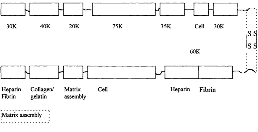
Figure 1. The modular domain structure of fibronectin... 21 (section 1.2.2).
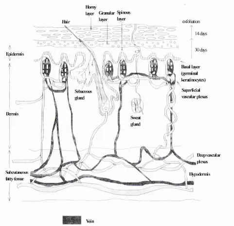
Figure 2. A full thickness, cross-section of skin showing the ... 26 structure of the epidermis, dermis, and hypodermis (section 1.3).
Figure 3. A flow diagram showing the processes used t o ... 37 prepare Ig of final protein precipitate in the preparation
of fibronectin cables (section 1.5).
Figure 4. The preparation of longitudinal fibronectin tubes... 44 (section 2.4.1).
Figure 5. Preparation of hollow tubes in spiral configuration ... 46 (section 2.4.2.).
Figure 6. Mechanical testing frame for Fn tubes (section 2.5.1)... 48
Figure 7. Schematic diagram showing the position of a ... 59 fibronectin tube when mounted on a hypodermic needle
and over a window (dimensions 0.25 x3mm) cut in the shaft (section 2 .1 2).
Figure 8. Flow culture system for Fn tubes (section 2.12)... 60
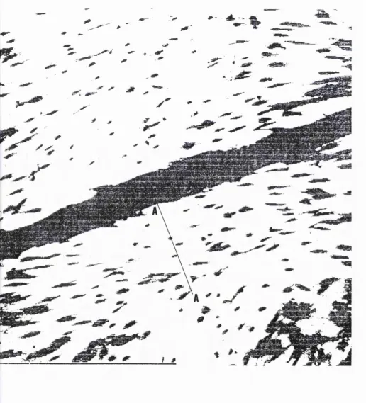
Figure 9. The alignment of human dermal fibroblasts alongside ... 6 6
and on the surface of a drawn fibronectin cable of width
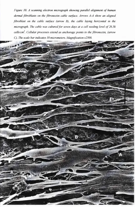
Figure 10. A scanning electron micrograph showing parallel ... 67 alignment of human dermal fibroblasts on the fibronectin cable
surface (section 3.1.1).
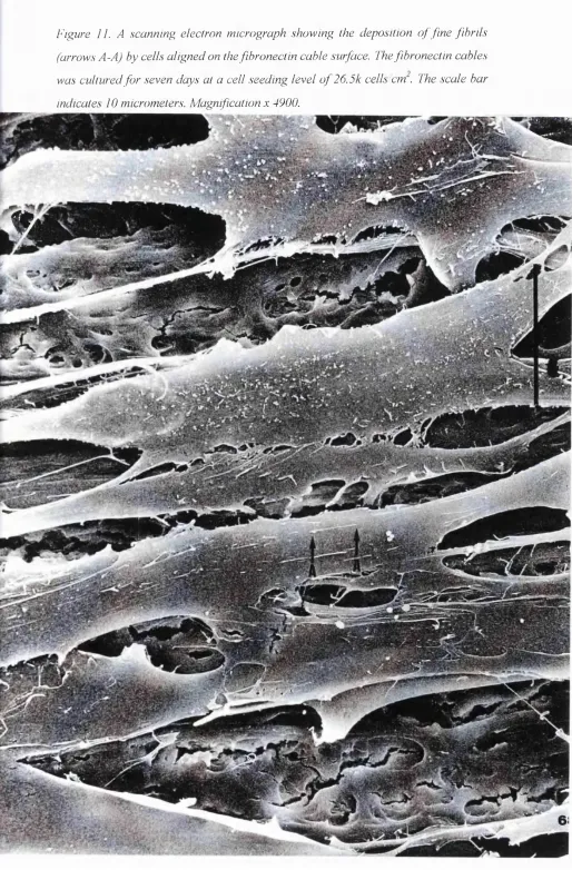
Figure 11. A scanning electron micrograph showing t h e ... 6 8
deposition of fine fibrils by cells aligned on the fibronectin cable surface (section 3.1.1).
Figure 12. Fibroblasts aligned alongside Fn cables displayed ... 70 as a polarised image from image analysis (section 3.1.2).
Figure 13a. Four separate graphs showing an increase in ... 71 the number o f aligned cell layers alongside different Fn
cable types, with an increase in the initial cell seeding level. (section 3.1.2).
Figure 13b. A combined graph showing the points as straight... 72 lines from the graphs in Figure 13a to more easily compare them
(section 3.1.2).
Figure 14a. Four separate graphs showing an increase in th e 73 cell docking band width alongside different Fn cable types
with increasing initial cell seeding level (section 3.1.2).
Figure 14b. A combined graph showing the points as straight lines . .. 74 from the graphs in Figure 14a (section 3.1.2).
Figure 15. A graph showing no correlation between cell layer ... 79 spacing in the cell docking band width and the cell docking
Figure 16. The difference in distance between cells in cell... 80 layers present on the Fn cable and on the glass substrata
(section 3.1.3).
Figure 17. There was no relationship between fibronectin... 81 cable width and the cell docking band width (section 3.1.4).
Figure 18. A graph displaying no relationship betw een... 84 Orientation Index value (S) and the cell docking band width
(section 3.1.6 ).
Figure 19. Scanning electron micrographs following culture ... 90 of human dermal fibroblasts (2 0k cells /cm^) on fibronectin
cable for 2hr and 4hr (section 3.2.1).
Figure 20. Compiled data of migration velocity (pm/hr) of H D F's 93 and PAE's towards Fn and 1% alginate Fn spun cable, versus
the initial cell distance (pm) away from cable (section 3.2.2.2).
Figure 21. Cell attachment to fibronectin seen by the immuno-... 94 staining of vinculin present in the cell adhesion plaque
(section 3.2.3).
Figure 22. The increase in cell numbers of human derm al... 95 fibroblasts on 9.6 cm^ of fibronectin/material over 16 days
from an initial ( (section 3.2.4).
from an initial cell seeding level of 2 0k cells/cm^ at day 0 .
Figure 23 The maximum tensile strength of fibronectin cable... 99 increased with more time in acid (0.25M HCl 2% CaCl2)
Figure 24. The number of Fn cable, protein coagulation ... 101 bands in cross section changed over time to reach a single
amorphous layer with a central core following 1 0 min in acid
(section 3.2.6).
Figure 25. Scanning electron micrographs showing the surface 104 of hand spun cable following dehydration in ethanol (Image 1),
acetone (Image 2) in relation to air dried hand spun cable (Image 3) and drawn cable (Image 4) (section 3.2.7.2).
Figure 26. A section of fibronectin tube sliced longitudinally... 107 down the tube length. The luminal and external surface are
indicated. The section was stained with sirius red and is at magnification x20 (section 3.2.8).
Figure 27. A low magnification image of Fn tube ... 108 lumen length cut in longitudinal section. Lines running
parallel with the tube length can be seen. Lines existing
across the cable joins are also seen (section 3.2.9).
Figure 28. The % of diy weight increase of four different ... 110 fibronectin cable types following full saturation in distilled
water for 1 hr at room temperature (section 3.2.10).
Figure 29. Freeze dried fibronectin tubes. The tubes a r e ... 113
approximately 2cm in length (± 0.4 S.D, n=20) with a dry weight of 0.0113g (±1.1x10'^ S.D, n=20) (section 3.3.1).
levels (section 3.3.2).
Figure 31 Breakage occurred at the butted junction o f ... 117 the tube, between neighbouring coils of fibronectin cable
when subject to burst pressure indicating that longitudinal stress predominated (section 3.3.3).
Figure 32. The relationship between longitudinal s tre s s ... 118 of the fibronectin tubes when assessing burst pressure, and
tube wall thickness (section 3.3.3).
Figure 33 Human microvascular endothelial cell g ro w th ... 120 in the fibronectin tube lumen following 30 min o f static
LIST OF TABLES
Table 1. Different collagen types and their location in the dermis 25 of skin (section 1.3).
Table 2. Orientation index values calculated from the c e l l ... 83 docking band width alongside different fibronectin cable
types (section 3.1.5).
Table 3. Migration velocities of two different cell types tow ards 91 two spun cable types (section 3.2.2.1).
Table 4. A table displaying data o f the increase in h u m an ... 96 dermal fibroblast numbers, cultured for 8 and 16 days on
different materials (section 3.2.4).
Table 5. Data of the average maximum tensile strength (M T S ) 100 of fibronectin cable versus the coagulation time (section 3.2.5).
Table 6 . The maximum tensile strength (MTS) o f Fn c a b le ... 102
increased after soaking in ethanol or acetone. The largest increase occurred after soaking in acetone (section 3.2.7)
Table 7. The maximum tensile strength (MTS, N /m m ^)... 114 of fibronectin tubes decreases with increasing relative
PUBLICATIONS
(1) Harding S.I., Underwood S., Brown R.A., Dunnill P. Assessment o f cell alignment by fibronectin multi-fibre cables capable o f large scale production. {Bioprocess Engineering, In press)
(2) Harding S.I., Afoke A., Brown R.A., MacLeod A.J., Dunnill P. Engineering properties of fibronectin-based tubes for vascular prosthesis (in preparation).
ABSTRACTS FOR CONFERENCE
(1) Harding S.I., Underwood S., Brown R.A., Dunnill P. Studies o f the orientation of human fibroblasts by fibronectin fibres: a model for large scale processing. Poster presentation at: The First Smith & Nephew International Symposium. Advances in Tissue Engineering and Biomaterials. University of York. 20-23 July 1997.
1.0 INTRODUCTION
1.1 Overview -Tissue engineering
Tissue engineering has been described as “a field combining the principles of engineering and the biological/medical sciences in application toward the production of biological substitutes, aimed at the creation, preservation, or restoration of organ function that has been lost” (Vacanti 1997). Biocompatable materials have been used as cell-support scaffolds onto which living cells are grown and then transplanted. If cell anchorage sites and appropriate structural cues are provided in a beneficial environment (eg. minimal inflammation), the intrinsic ability of cells to re-organise and generate new tissue is enhanced (Vacanti 1997). Materials to date that have been used for tissue engineering studies, include polyglycolic acid, polylactic acid, calcium alginate, polyethylene oxide and polypropylene oxide. Tissues studied include collagen, bone, skin, and liver. This work has been undertaken by many contributors and establishments, the most influential being Charles and Joseph Vacanti, and Langer and colleagues based at Massachusetts, USA (1988,1993,1995,1997,1999). The approach adopted in this study is to describe the potential of a natural, human derived composite material of fibronectin (65% ) and fibrinogen (35%), to be used as a scaffold in skin replacement therapy following wounding such as severe bums; and as a scaffold conduit for culture and use in vascular surgical bypass procedures.
1.2 Fibronectin (Fn) and fibrinogen (Fgn) -Provisional wound healing matrix
proteins
The majority o f the matrix proteins have specific peptide sequences that are short, and are bound by cell surface receptors. Amino acid sequences as short as 3 to 5 residues within the proteins can act as cell surface receptors, and adhesive recognition sequences. Sequences sometimes have intrinsic cell-type specificity, or need a complementary site to provide high affinity and specificity to an adhesion site that would otherwise be less specific. These molecules form interchain disulfide bonds at specific residues or form noncovalent self associations, and are organised into polymers or oligomers. There are structural units that repeat. Fibronectin or epidermal growth factor-like repeats can comprise a large part o f some of these proteins. In these repeats there are domains which can be specialised for diverse fimctions. A healing wound contains complex mixtures of extracellular matrix proteins, each of which may contribute independently and synergistically for final effects on cell behaviour (Clark 1996).
1.2.1 Fibrinogen
1.2.1.1 The role of fibrinogen in blood clotting
The conversion o f fibrinogen to cross-linked fibrin is the last step in the blood coagulation pathway. At the amino terminus of fibrinogen, cleavage of fibrinopeptide A and B by thrombin, exposes two types of binding site. These binding sites have a role in fibrin polymerisation (Mosesson 1992). Noncovalent lateral assembly occurs between the new alpha amino terminal ends and sites in the gamma chain carboxy termini of adjacent molecules. Lateral aggregation is re-enforced by gamma chain interaction also, with the new beta chain amino terminal ends. This results in the formation of thicker fibres. Protofibrils result from the polymerising and the
staggered overlapping of the fibrin. Lateral protofibril associations occur, forming thick fibrin fibres that intertwine to produce a clot. Cross-linked fibrin has been found to promote fibroblast migration into the clot matrix. The study of aged clots has shown that highly cross-linked fibrin may inhibit cell penetration (Brown et al
1993). Fibronectin is associated with fibrin in blood clots and is critical for cell migration into a clot (Knox et al 1986). In normal wounds the provisional fibrin matrix may promote cell recruitment into the defect by providing essential scaffolding for cell migration (Ciano et al 1986, Brown et al 1993). Fibrinogen- fibrin, its derivatives, and fibronectin may promote cell migration (Clark et al 1988, Leavesley et al 1992), and proliferation (Michel and Harmand 1990, Gray et al 1993) through direct coupling of extracellular matrix receptors on the cell surface (Damsky and Werb 1992). It has been suggested that fibrin may act as a reservoir for critical factors for cell proliferation and migration, as it has the ability to bind thrombin (Liu et al 1979), transforming growth factor beta (TGF-P), and platelet derived growth factor (Clark 1996).
1.2.2 Fibronectin
wound repair (Clark and Henson 1988). Functions o f fibronectin include the mediation o f cell adhesion by selective binding, the promotion o f cell migration and monocyte chemotaxis, and a role in the regulation of cell growth and gene expression. The fibronectin molecule consists o f a series of functional domains and cell binding sites, and allows the interaction of fibronectin with a wide range of cell types, extracellular matrix proteins and cytokines.
There are number of different types of fibronectin molecule, due to alternative splicing of its precursor mRNA and as such, fibronectin cell-type binding specificity can be regulated. There may be 20 different variants of human fibronectin depending on the particular combination of spliced sites, however all fibronectin molecules consist of the same basic functional domains (Figure 1).
Cell 30K
40K 20K 35K
30K 75K
S5 S5 60K
Heparin Collagen/ Matrix Fibrin gelatin assembly
Cell Heparin Fibrin
(Matrix assembly
1.2.2.1 Soluble and insoluble fibronectin
Fibronectin is present in blood as a soluble plasma glycoprotein at an average concentration of 0.3g/liter (ten times less than Fgn), and termed “plasma fibronectin”. It is secreted into the blood principally by hepatocytes, but also by other cell types including macrophages and endothelial cells (Saba 1980). Endothelial cells produce Fn in rough endoplasmic reticulum prior to secretion into the blood stream. (Saba
1980). Soluble fibronectin is also found in other body fluids eg. amniotic fluid (Chen et al. 1976), seminal fluid (Vuento et al. 1980, Gressner, Wallraff. 1981), joint fluid (Carsons, et al. 1981, Scott, et al 1981, Vartio. et al 1987), and cerebrospinal fluid (Kuusela. et al 1978). The concentration of plasma fibronectin is regulated by the liver and kidneys (Saba 1980). During certain illnesses the level of plasma fibronectin decreases, including hepatic dysfimction, septic shock, trauma and thermal injury (Saba 1980). Following intravenous injection o f radiolabelled plasma fibronectin, clearance from the circulation occured with a half life of 24-72 hours in a healthy individual (Mosher et al 1984). During injury the turnover of fibronectin is increased (Saba 1980), and an alternative fibronectin pool can be mobilised, or dynamic synthesis can occur to re-establish the fibronectin level (Saba 1980). Soluble and insoluble fibronectin may be able to role reverse following depletion of either form (Saba 1980). As fibronectin is present in plasma, it is thus initially present in wound healing clots in substantial concentrations.
Insoluble fibronectin is termed “cellular fibronectin”, and is produced by a wide variety of cell types, which secrete them and organise them into extensive extracellular matrices. Cell types include fibroblasts, Schwann cells, endothelial cells, chondrocytes, myoblasts, and some epithelium cell types (Atherton and Hynes
1.2.2.2 Fibronectin localisation
Fibronectin has been identified in many tissues during a number of developmental, repairative, and pathogenic events (reviewed by Clark 1996). It functions as a biological adhesive, promotes cell migration, and stimulates collagenous matrix formation. Along with other extracellular proteins, fibronectin is particularly prominent in migratory pathways for embryonic cells, such as those for gastrulation, precardiac mesoderm cell migration, and neural crest migration. Fibronectin has been localised characteristically in loose connective tissue and in embryonic basement membranes. In wound healing, fibronectin is present in large quantities in the fibrin clot where it acts as a substrate for migrating cells. Various fibrotic processes involve the deposition of fibronectin (Carsons 1989).
1.2.2.3 Fibronectin gene structure
regulated by a number of growth factors and cytokines, eg. transforming growth
factor beta (TGF-P) (Yamanda 1989). The identity of all of the transcription factors needed for the regulation of gene expression is not fully known.
1.2.2.4 Functional associations of fibronectin
Fibronectin is like other extracellular matrix proteins, in that it can act as a reservoir
for the binding of growth factors and cytokines. Fibronectin tightly binds TGF-p and this growth factor can be recovered by acid extraction (Fava and McClure 1987). The
amino-terminal domain of fibronectin binds to tumor necrosis factor-alpha (TNF-a), and while immobilised, the growth factor retains high activity (Alon et al 1994, Hersh-koviz et al 1994). Extracellular matrix-bound factors such as these may provide an immobilised store of growth factor that can be held closely to cells for cell activation, or released after proteolysis of the matrix protein carrier. Fibronectin can also bind molecules such as complement proteins, yeast, bacteria, DNA, and denatured actin. These interactions have yet to be established with regard to biological role. It has been suggested that one function may be as a scavenger or opsonic molecule, to promote the clearance of such materials from the blood by the reticuloendothelial system (Carsons 1989).
1 3 SKIN
compression within limits. There are two general skin types: thin and hirsute (the majority o f skin), and thick and hairless (palms o f hands, soles of feet, digit flexor surfaces). Skin has a number of lines, visible and non visible; and has numerous collagen types in different skin regions. Dermal collagen is composed o f types I (80- 85%, course) and HI (15-20%, fine), situated in the reticular and papillary dermis respectively. Different collagen types and their locations are summarised in table 1.
Dermal collagen type Localisation
I reticular dermis
m
papillary dermisIV basal lamina
V lamina lucida and around cells
VI forms a microfibrillar network, enmeshing nerves and vessels
vn
anchoring fibrilsTable 1. Different collagen types and their location in the dermis o f skin
Honty
Q ^ a r S^iraxB
lajo* la>€r exfdiadon
14(%5
30
Basal l^ er
(geminal kératinocytes)
SifKrfidal vasciiar plexus E^demis
Derms
Subcutaneous
Êtty tissue
] DeepvasoMar plexus i^podemis
Vdn
Artery
Figure 2. A full thickness, cross-section o f skin showing the structure o f the
epidermis, dermis, and hypodermis. Skin tickness ranges fro m 1.5-4.0mm depending
13.1 The epidermis, dermis, and hypodermis
The epidermis consists of a modified, stratified, squamous epithelium that arises from basal, germinal, columnar kératinocytes. The kératinocytes evolve as they migrate towards the surface and through the prickly (spinous) layer. In the prickly layer the cells acquire a polyhedral shape. The cells become nucleated in the granular layer, acquire keratohyalin granules, and form the superficial keratinised layer (homy layer). In the homy layer the cells lose their nuclei and form a tough external layer. Epidermal cells are linked by desmosomes. The epidermis resides on a thin basement membrane and anchorage to the dermis occurs via hemidesmosomes and proteins such as laminin, basement membrane proteoglycan, and type IV collagen. In the basal cell layer melanocytes develop from neural crest cells, and synthesise melanin pigments which are transfered to kératinocytes through dendritic processes. Skin pigmentation forms protection against harmful ultraviolet radiation.
The dermis consists o f a fibrous matrix of collagen and elastin, fixed in a ground substance of glycosaminoglycans, hyaluronic acid and chondroitin sulphate. Nerves, blood vessels, fibroblasts, and various inflammatory cells reside in this layer. Skin appendages such as sebaceous glands (waterproof and skin lubrication), apocrine (concentrated in eg. anogenital regions and eyelids) and eccrine glands (sweat glands), are set in the dermis. The dermis comprises of two layers: the papillary dermis and the reticular dermis. The papillary dermis opposes the undulating dermal-epidermal junction, and the reticular dermis lies beneath this, forming the bulk of collagen, elastic fibres and ground substance. Dermal fibroblasts synthesise and secrete collagen types I and HI, and elastin. Disruption to dermal
elastin causes wrinkles and loose skin formation.
The dermis resides on the hypodermis which comprises of subcutaneous fat and loose connective tissue. The role of this layer includes fat storage and insulation.
1.3.2 Dermal wound healing
and may also be important in epithelial cell migration (Berman et al 1983). Following all the migration o f cells to the wound site, fibronectin may promote the reorganisation o f the basement membrane underlying the epidermis (Brownel et al
1981). Fibronectin accumulates at times of increased vascular permeability and is produced by blood vessels in response to injury (Clark et al 1982).
1.3.3 Skin replacement therapy
templates (Ejim et al 1993).
Fibronectin (Fn) mats have been prepared as tissue repair guidance templates in the form o f cables for dermal, tendon and nerve injuries and as substrates for tissue engineering (Prajapati et al 1996, Brown et al 1994, Wojciak Stothard et al 1997, Whitworth et al 1996). Subsequently, single cable forms of fibronectin (Fn-cables) have been made to orientate wound repairing cells (Underwood et al 1999). Cell alignment on such cables is critical to their function and so a quantative assessment of alignment has been developed in this study to test cables capable of being prepared by large scale processing techniques. Fibronectin may potentially be used for contact guidance in the healing of bum wounds by structurally organising cells and for other tissue engineering purposes such as nerve repair.
1.4 BLOODVESSELS
large arteries slowly release stored energy, maintaining a relatively high mean arterial pressure and a constant flow of blood through capillaries. The arteries and arterioles smooth out the pulsatile flow of blood from the heart. Capillaries do not have smooth muscle coats. The structure of capillary endothelium differs in different organs due to solute and fluid permeability and organ specificity. Capillaries in general consist solely o f a single layer of closely joined endothelial cells, allowing water and small hydrophobic solutes to pass between the plasma and interstitial fluid. Capillaries in most regions of the central nervous system have a low permeability even to small organic solutes. These capillaries constitute the blood-brain barrier. In the kidneys, endocrine glands, intestine, and liver, capillaries may have large pores (fenestrated capillaries), or gaps (discontinuous capillaries) (Kapit and Elson 1993). Systemic (to the body as opposed to the lungs) vessels differ in size, the blood pressure they support, and the rate of blood flow through them. Blood pressure is pulsatile due to systolic and diastolic heart movements in the aorta, arteries and arterioles. The aorta is the main vessel from the left side/systemic side of the heart. It is approximately 5cm in diameter and supports the total cardiac output of 5000ml/mia Blood pressure in the aorta is approximately 120/80 mmHg (systolic/diastolic) when resting, and can be elevated to > 190 mmHg during exercise. Blood branches from this vessel into arteries and arterioles, increasing the blood-vessel surface area and decreasing the blood pressure through individual vessels. Pressure decreases to 100/70 in arteries, and 50/40 in arterioles. Vessels vaiy in diameter according to their situation in relation to the larger or smaller vessels. Arteries decrease in diameter from the aorta to arterioles. Arterioles range from 4-25 micrometers in diameter (arteiy end- capillary end). Capillaries, venules and veins also differ in diameter and are subject to laminar blood flow of a blood pressure average o f 20mmHg, lOmmHg, and 2mmHg respectively. A typical capillary has a diameter of 5 micrometers, and a blood flow of
Iml/min.
1.4.1 Vascular endothelium
forming this layer is crucial to the success of tissue engineered, vascular grafts. It represents the primary anatomical site that separates the blood from the body's interstitium (Simionescu and Simionescu 1988). The endothelium is constantly exposed to hemodynamic stress posed by blood flow, blood pressure, and wall distension (Davies, et al 1994). In addition to mechanical stimulus, chemical signals are received, blood-bome and tissue derived, which may induce endothelial responses by acting on the vessel wall itself or at distant target sites. (Luscher 1995). These signals may play important roles in the modification of the primary function of the endothelium ie., the accurate control of solute passage, macromolecule and blood cell passage across the vascular wall (Cuny 1994, Michel 1992). As a barrier between blood and interstitium, and as a transducing surface, the structural integrity of the endothelial monolayer is critical. The layer must be able to adapt to changing hemodynamic situations and tolerate adverse conditions such as ischemia, hypoxia and oxidants. The endothelium can respond to injury with specific repair mechanisms such as angiogenesis (Folkman and Shing 1992, Risau. 1995), or re- endothelialisation of the naked vascular intima (Bjorkerud and Bondjers 1971, Schwartz et al 1975). Functional properties of the endothelium need active changes in cellular shape, and the generation of internal isometric forces to counteract the changing hemodynamic loads acting on the cell monolayer. Basic endothelial fimctions are controlled by an actin and myosin-based contractile cytoskeleton (Davies 1995, Drenckhahn. 1983, Garcia and Schaphorst 1995, Gotlieb et al 1991).
1.4.2 Coronary atherosclerosis and thrombosis
restored to the muscle, function will return (unless the muscle has been permanently damaged) and the angina will stop.
Atherosclerosis is a complex process, characterised by lipid, macrophage, and smooth muscle cell accumulation in intimai plaques. Endothelial injury, contributed by mechanical shear stresses, biochemical abnormalities, and immunological factors, is believed to trigger atherogenesis. The endothelial dysfunction allows oxidised lipoproteins to accumulate. They are taken up by macrophages to produce lipid-laden foam cells. Macrophages further accumulate and smooth muscle cells migrate and
1.43 Blood vessel grafting
Materials potentially available for coronary bypass include autologous veins, replumbing arteries (with internal mammary arteries), and artificial conduits. Although in most cases autologous vein transplant produces satisfactory results, incidences of side effects are known to occur (Cox et al 1991). Problems of rejection arise with the use o f donated vessels (Hosenpud et al 1996, Dong et al
1996), and artificial vessels made of plastic or silicone are thrombogenic and can only be used for vessel diameters exceeding 6mm (Ott and Ballerman 1995). Attempts to develop a tissue engineered vascular graft have involved the use of temporary polyglycolic acid (Niklason and Langer 1997) and polytetrafiuoroethane supports (L'Heureux et al 1998) on which to grow smooth muscle and endothelial cell layers.
Fibronectin is a protein present in extracellular matrices and in blood. It has a number o f roles in wound repair (Grinnell 1984, Grinnell et al 1984); including cell adhesion (Mosher 1984, Hynes 1985), cell migration (Grinnell 1984), and in angiogenesis (Ungari et al 1985). The physical properties o f a fibronectin based polymer as a solid cable for use as a tissue engineering material have been characterised by Underwood (Underwood et al 1999, Underwood (PhD thesis)
due to its nature of being a normal matrix protein and would be unlikely to cause resorption problems. Fibronectin would also release large amounts of weakly incorporated fibronectin over the first few days, which would promote local recruitment o f endothelial cells and new microvessels (Bowersox and Sorgente 1982, Ungari et al 1985). The cell adhesion function of orientated fibronectin, would serve to provide resident cells with directional attachment and topographical cues. The presence and conformation of substrate fibronectin is important for the adherence of aortic endothelial cells under flow (luliano et al 1993). A combination of the substrate density of fibronectin (as an attachment ligand), and the cell membrane density o f appropriate integrins, is the rate limiting factor for cell migration (Palecek
et al 1997). Endothelial cells express integrins including a l p i, a2 p i, a3 p i, a5 p i,
av p3, four of which bind to fibronectin (Dejana et al 1992). There is a switch to the
expression of a v p3 during cell migration in angiogenesis. This integrin is necessaiy for microvascular invasion, and binds to fibronectin among other clotting proteins. It is expressed to enable cells to migrate and attach to components of the fibrin clot and provisional repair matrix. It would follow therefore, that fibronectin may be a favourable adhesion substrate for promotion of this transient receptor pattern. Copper has been shown to stabilise fibronectin in mat form (Ahmed 1998). The use of copper may be benefitial in vascular grafting as it has been reported to promote angiogenesis (Raju et al 1982, McAuslan 1980, Brem et al 1990, Ziche et al 1987). Revascularisation is critical to nerve repair also.
1.5 Fibronectin source and preliminary fibronectin cable preparation
4% PEG
0.54 litre
plasma cryo ppt.
\+ 48.6ml ; phosphate buffer* I to dissolve
10% PEG > I hr
centrifiige 4500 rpm V15min Fgn pellet (approx.2.9g) discard centrifiige 4500 rpm Vl5min supernatant discard +333ml O.IM )hosphate buffer containing 25mM trisodium citrate 3mg/ml protein solution for drawr cable production 0.75g water 0.15g protein 65% Fn i^[0.0975g)
\ 35% Fgn (0.0525g) -K).016g sodium alginate 40.32ml 6Murea 14% protein spinning solution containing 1% sodium alginate
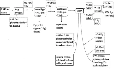
Figure 3. A flow diagram showing the processes used to prepare Ig o f final protein
precipitate used in the preparation o f fibronectin cables.
The physical properties of fibrillar cables of fibronectin, drawn up following protein precipitation from solution, have been characterised by Underwood et al (1999). Underwood's work went on further to produce hand spun cables of fibronectin, and to undertake pilot scale production of fibronectin cables on a purpose designed
either increasing the protein content or increasing the alginate content respectively. A 98mg/ml protein solution containing no alginate exhibited Newtonian behaviour between shear rates of 30-1007 s'^ and had a viscosity o f 55mPa s. By increasing the protein concentration to 140mg/ml, and with the addition of 1% sodium alginate, a shear thinning solution was formed with an apparent viscosity of 413 mPa s at a shear rate of 1007s ', and had a better spinning quality. Compared with this solution, with the same shear rate the spinning quality was increased further and had a 3-fold higher viscosity by increasing the alginate addition to 4.8% with a reduced protein concentration of 46mg/ml. The high protein cables were stronger than the high alginate cables, with maximum tensile strength values of 28 N/mm^ and 6 N/mm^ respectively. The high protein cables had an average diameter of 563 pm ± 33 and a tenacity of 0.054 g/denier. The high alginate cables had an average diameter of
635pm ±17 and a tenacity of 0.017 g/denier. (Underwood et al submitted).
The hand spun and drawn cables (Underwood et al 1999) developed prior to the work outlined above, form the basis for the functional testing of fibronectin in this
study.
1.6 Aims of the study
The aims of this study were to investigate the phenomenon of cell alignment next to individual fibronectin fibres, and quantitate the various culture parameters involved leading to defined extents o f alignment, thus developing a quantitative test system. This
was with a view to the culture o f continuously aligned fibroblast sheets that could be implanted into a cutaneous wotmd and result in a more organised granulation structure
with reduced scarring and wound contraction. I aimed to prepare fibronectin hollow tubes, suitable for use as nerve regeneration conduits and as scaffolding for vascular grafts. The tubes were to be tested for mechanical and cell attachment properties, to give insight into
2.0 MATERIALS AND METHODS
2.1 Fibronectin material preparation and characterisation
2.1.1. Fibronectin material preparation
Fibronectin was obtained as a gift from the Scottish National Blood Transfusion Service (SNBTS, Protein Fractionation Centre, Edinburgh, EH17 7QT) following isolation from human plasma by cryoprecipitation. Most of the fibrinogen was removed from protein liquor (cryoprecipitate dissolved in O.IM phosphate buffer (0.0IM Na2HP0 4, 0.0IM NaH2?0 4 . 2H2O, 0.15M NaCL, pH 7.0, in the ratio 1:5
w/w) by a two-step precipitation (37^C) starting with the addition of 4% (v/v) polyethyleneglycol (PEG) for Ihr. The precipitate was discarded following centrifugation at 4500 rpm (Centaur 2 centrifuge 4222mkll, Camlab Ltd., Cambridge) for 15 min. The PEG concentration (v/v) was then raised to 10% for 2 hr to form precipitate. Fibronectin formed pellets following centrifugation at 4500 rpm for 15 min. The pellets, comprising of approximately 65% fibronectin, 35% fibrinogen, (termed fibronectin subsequently) were suspended in O.IM phosphate buffer containing 25mM trisodium citrate, to a final concentration in solution of 3 mg/ml. This solution was used in all subsequent experiments for the production of drawn fibronectin cables (See section 2.1.5), or kept in solid precipitate form for spinning (Section 2.1.6). Fibronectin solutions and precipitates were stored at -20°C and thawed at 37®C prior to use. Batches o f fibronectin were prepared and used from
mJi
2.1.2. Total protein assay
A total protein assay was used to measure the total protein content of the fibronectin precipitate obtained from PEG precipitation. Total protein was measured using The Bradford (Bio-Rad) protein assay reagent (Bio-Rad, Munich, Germany), diluted by 1:5 with distilled water. Protein standards (albumin/globulin standards. Sigma J68571) were diluted with distilled water to concentrations of 0.1 to 1.0 mg/ml and
assayed alongside fibronectin samples of dilution 1:100 in duplicate. lOpl of samples
plus 250j l i1 of assay reagent were added to 97 well plates (Sterilin Ltd. Feltham, UK).
The colour generated was recorded against distilled water blanks with a plate reader
(Dynatech 7000) at 570nmÀ. A standard curve of absorbance (y) against protein standard concentration (x) was plotted using the Cricket Graph package (Computer associates, Microsoft Corporation, Redmond, WA, USA). A 'simple' fit was applied, yielding a line equation (y = a + bX). The sample absorbance value, once averaged and with the blank value subtracted, was put into the equation to find the protein concentration in mg/ml (Sample -a/b x dilution).
2.1.3. Fibronectin (Fn) and fibrinogen (Fgn) assay
Accurate Fn and Fgn assays were undertaken at the Protein Fractionation Centre,
biochemical services department (Edinburgh). In these analyses immunoabsorbant techniques were used for Fn and Fgn quantitation. As a preliminary guide, the total protein was measured (method 2.1.2) and the Fgn content determined by a clotting assay. As the remainder of the protein is fibronectin, this too could be estimated. The fibrinogen content of the total protein was assayed against a reference sample (Sigma Cat. no. 880-10) diluted in distilled water to generate a calibration curve from 0.2-2.5 mg/ml Fgn. Protein samples were diluted by 1: 2, 1: 5 and 1:10, and 100 pi of sample
was transferred to a 96 well plate, with lOOpl clotting reagent (20mM Tris, 40mM tri-sodium citrate dihydrate, pH 7.5). The plate was wrapped in foil and heated at
curve was constructed and the absorbance converted into mg/ml Fgn as in method
2.1.2.
2.2 Scanning electron microscopy (S.E.M)
In order to view the surface structure of Fn cables and cells cultured on them, scanning electron microscopy was used. Dry samples were gold sputter coated for 3 min under vacuum (0.07 Torr) with a current of 15-20 mA. They were viewed with a Jeol 5400LV model scanning electron microscope (Tokyo, Japan). Wet samples, following fixation in 4% paraformaldehyde in phosphate buffer pH 7.4 (4°C) for 2 hr, were transfered to O.IM phosphate buffer pH 7.4 for 5 min (twice), and distilled water for 5 min. The samples were dehydrated in an ethanol series progressively from 50-100% ethanol (20 min at each %). They were then surface covered with hexamethyldisilizane (HMDS, Taab labs, Berks.) and allowed to air dry for 30 min. The samples were gold sputter coated (Polaron sputter coater, SC500, Kent, UK) and viewed on the S.E.M.
2.3 Fibronectin cable preparation
2.3.1 Drawn fibronectin cable preparation
The first fibronectin cables made were prepared by the drawing of protein from solution (method by Sarah Underwood 1999). They were used to investigate human dermal fibroblast alignment alongside fibronectin cables, and compared with cell alignment data obtained using different preparations of fibronectin cable (method 2.3.2). Fibronectin was precipitated out of solution (3 mg/ml, prepared from method 2.1.1) by adding O.IM citric acid (pH 3.5) in the ratio (v/v) of 2:1 (Fn solution:acid). This resulted in protein aggregates at pH 4.5 which were drawn up into cables with
2.3.2 Hand spun fibronectin cable preparation
Fibronectin cable development undertaken by Sarah Underwood led to the preparation of hand spun cables. Cables were spun from fibronectin precipitate (prepared from method 2.1.1) To a Ig aliquot of precipitate, approximately 1ml of 6M urea was added to dissolve the fibronectin and result in a viscosity ' loose' enough to extrude through an orifice diameter of 0.5mm without clogging. The final protein concentration was approximately 8.6% (w/v) (Appendix 7), up to a volume of 2ml. The solution was rolled on a mechanical rotator (Denley mechanical rotator, Jencons Ltd., Bedfordshire, UK) for 1 hr to dissolve the protein. Air bubbles were removed from the dissolved solution by vacuum at 2x10'^ Torr for 20 min. Fibronectin solution was extruded from a 1ml syringe through a hypodermic needle (0.5mm x 16mm) barrel into an acid bath (0.25M HCl 2% CaCl2) to coagulate the protein. This
resulted in the precipitation of dissolved fibronectin into solid cable. The cable was then transferred to phosphate buffered saline (PBS) (pH 7.4) and was washed by mechanical rotation for 10 min.
Fibronectin cable containing 1% alginate was prepared by the addition of 1% solid sodium alginate (per solid protein weight) prior to dissolving the fibronectin in 6M urea as above.
2.4. Fibronectin tube preparation
Tubes of fibronectin were prepared and mechanically tested for potential uses in vivo for peripheral nerve regeneration (work done by Barker G., Prof Standring 1998, Division of Anatomy, Human and Cell Biology, Guys Campus, GKT, London, SEl 9RT) and in vitro for the luminal culture o f endothelial cells, to mimic a capillary-type structure.
2.4.1. Fibronectin tube preparation in longitudinal configuration
Figure 4. (2.4.1) The preparation o f longitudinal fibronectin tubes:
1.
4cm
V
Steel wire 0.75-1.0mm diameter
2.
1ml syringe
Acid bath
0.25M H cl2% C acl 2
Putty rubber
A w ire is fixed inside a syringe w ith p u tty . T h e syringe is th en filled w ith acid
3.
\ /
A second syringe is filled with fibronectin solution and extruded over the wire into the acid
Acid displacement by fibronectin
Acid displacement by fibronectin
S h e a r as fib ro n ectin falls over th e w ire p ro d u ces lon g itu d in al layers. A tu b e
is form ed w ith an in tern al d ia m e te r 0.75-1.0m m a n d a wall thickness o f 1.0-1.25m m .
The tube inside the syringe is frozen
(12hr -2(5C), and freeze dried 12 hr.
4. The freeze d ried tu b e is removed from th e w ire by pulling the w ire from th e syringe an d pushing the tu b e from the w ire
2.4.2. Preliminary tube preparation in spiral configuration
Spinning solution of fibronectin or fibronectin containing 1% alginate was prepared as in method 2.3.2. Fibronectin solution was extruded from a 1ml syringe into an acid
Figure 5. (2.4.2.) Preparation o f hollow tubes in spiral configuration:
1. Spinning solution extruded
from a 1ml syring into
an acid bath to form a
flattened cable
0.25M HCl 2%Cacl2 Flattened Fn /I % Alg -Fn cable
\ /
2. Cable wash in PBS
3. Cable lifted out o f
solution and spiral wrapped
around wire wire
PBS washing bath
2.4.3 Fibronectin tube preparation in spiral configuration-modified method
The method for spiral hollow tube preparation (2.4.2) was revised due to preparation difficulties. To improve the method, Fn cable that was hand spun through an orifice was used instead of flattened cable. Hand spun cable (method 2.3.2) was wrapped around a hypodermic needle (0.8x40mm) to result in increased control of stmctural dimensions and to make the method reproducible. A single cable was used to form
each tube (ie. no breakage’s and additions) and each spiral was closely butted against the next. The tube was lefl; to air dry and was then freeze dried. The tube was removed from the needle by gentle finger pressure. Fn tubes prepared from this method were mechanically tested and used for in vivo peripheral nerve regeneration studies and in vitro endothelial cell attachment studies.
2.5 Mechanical testing of fibronectin tubes
2.5.1 Tensile tests of freeze dried tubes
/■
A crylic cro ss pieces B
Fibronectin tube
Force
u
n:s
1 u
G au ge length.I
Figure 6. M echanical testing fra m e f o r Fn tubes
2.5.2 Tensile tests of fully hydrated tubes
The same test procedure for the freeze dried tubes was used for this test. However, prior to testing, the tube was allowed to hydrate fully. This was achieved by wrapping cotton wool saturated in unsupplemented culture media (Dulbeccos Modified Eagles Medium (DMEM), Gibco, Scotland) around the tube. Force was measured with a ION load cell, and the specimen tested at an extension rate of 10mm min '. The faster rate was used as the tubes were expected to stretch to a degree, and it was felt that the higher rate would be more accurate in assessing the strain to failure rate. A force/extension curve was obtained on an X/Y plotter for each tube tested.
2.5.3 Burst pressure
bath of unsupplemented growth media (DMEM, Gibco, Scotland, UK). A hydrostatic pressure o f 10mm Hg was applied and the tube was allowed to swell to its maximum diameter, this usually t^kes" about 1 hr. The external diameter was then measured using a travelling microscope and pressure was increased in steps of 10 mm Hg every 2 minutes until the tube burst. The experiments were conducted at room temperature. From the burst pressure, the circumferential and longitudinal stress of the fibronectin tube was calculated (Appendix 8).
2.6 Fibronectin cable characterisation
Hand spun fibronectin cable was characterised with regard to orientation (1), hygroscopic (2) and solubility (3) properties, coagulation time relating to structure (4) and strength (5), and dehydration methods relating to strength (6). As tubes are made up of individual cables, points (2-6) were undertaken on cables alone.
2.6.1 Polarisation microscopy and S.E.M. to determine Fn cable and tube orientation
Drawn fibronectin cables were found to be highly fibrillar and orientated down the
w t i
length of the cable (Underwood et al 1998). Spun cable in contrast isrhon fibrillar and lool^sim ilar to a solid 'rod' shape. Cable wound into tube was assessed for orientation in the tube format.
2.6.1.1 Polarisation microscopy
2.6.1.2. Fn tube orientation viewed by S.E.M
Fibronectin tube was prepared as in method 2.4.3. Following freeze drying the tube was rehydrated in distilled water (Ihr), and sliced longitudinally with a scalpel down the centre of the tube. The tube halves were prepared for S.E.M and viewed on a scanner (method 2.1.4).
2.6.2 Hygroscopic properties of fibronectin cables
For drawn, hand spun, preliminary machine spun Fn cable and pure alginate cable, the extent of water uptake as % of the dry weight was measured. Fn cable (0.8g freeze dried) was added to 5ml of distilled water in a petri dish. The dish was covered and left at room temperature for an hour to allow full hydration. The cable was then dried by gentle paper tissue application and re-weighed. Results of % weight increase were plotted. The experiment was repeated twice in duplicate.
2.6.3. Coagulation time versus cable structure in cross section
Fibronectin cables viewed in cross section are composed of a number of bands' of coagulated protein.
Cross section o f Fn cable indicating the appearance o j bands o f protein
series system, Apple Computers Inc., Ca, USA).
2.6.4. Coagulation time versus cable tensile strength
To investigate cable tensile strength in relation to coagulation time in acid, fibronectin cables were prepared as in method 2.3.2, with coagulated times in acid that were used in method 2.6.4. The cables were washed in 200mM Tris buffer pH7.4 (20 min), in distilled water (Imin), were allowed to air dry (12hr) and then were freeze dried (2hr). To ensure the cables were straight (as needed for tensile testing), they were air dried over a metal frame after being pulled straight. Cables was cut to a length o f 2cm and tested for maximum tensile strength (section 2.5.1).
2.6.5 Dehydration method versus cable tensile strength
Fn cable was prepared as in method 2.3.2 and transferred from distilled water into either 70% ethanol (10 min), 70% acetone (10 min) or were just air dried. All cables were air dried (12 hr), cut to 2cm in length and tested for tensile strength (method 2.1.8.1). Cable prepared from the above was (1) viewed by S.E.M (section 2.2), and (2) stuck onto glass coverslips for gamma irradiation and subsequent cell culture to see if they would support cell attachment. Cables at a spacing of 4mm on glass coverslips were seeded with 30k cells/cm^ in 1ml medium for 24hr (37°C, 2.5%
CO2).
2.7 Cable de-acidification
2.8 Primary cell culture
For the functional testing in vitro of Fn cables and tubes, a number of cell types were used. They were obtained from tissue donated from surgery (Middlesex Hospital) with the exception of pig aortas which were delivered from a nearby abattoir and gained via Prof Salvador Moncada, The Cruciform Project, UCL.
2.8.1 Human dermal fibroblasts (HD.F's)
H.D.F's were harvested to use in alignment studies by fibronectin with a view to potential use in skin replacement therapy.
Human dermal fibroblasts were obtained from whole skin taken from abdominoplasty and breast reduction surgery. The skin was scraped free of fat, cut into thin strips (3-4mm diameter), agitated briefly in 70% ethanol to wash free of blood and transferred to sterile PBS. Small squares were then cut (3-4 mm by 3-4 mm) and transferred to 25cm^ culture flasks (Coming, Nottingham, UK), epidermis facing upwards. The explants were incubated at 37°C for 1 hr for skin - flask adherence and then covered in Dulbeccos modified Eagles medium (DMEM) (Gibco, Paisley, Scotland), supplemented with 10% fetal calf serum (FCS) (First Link Ltd. West Midlands, UK), penicillin (Gibco, Paisley, Scotland), and streptomycin
(lOOpg/ml) (Gibco, Paisley, Scotland), and L-glutamine (2pg/ml) (Gibco, Paisley, Scotland), and was termed “complete”. The explants were cultured (37°C, 2.5% CO2) for 3-4 weeks. The fibroblasts generated from the explants grew migrating
2.8.2 Endothelial cells
Endothelial cells were used to investigate cell attachment within fibronectin hollow tubes. Cells were harvested from human and porcine sources, and bought from a human source.
2.8.2.1.Human umbilical vein endothelial cells (HUVEC's)
HUVEC's were obtained from veins of whole umbilical cords taken from normal vaginal birth. The cords were used within 12 hr of birth, following storage in sterile Hepes -buffered saline (HBS, pH 7.4) at 4°C. The cords were transferred to a foil covered cork board and into one end of the vein, a canula was inserted. It was tied and sutured into place with wax covered silk suture cord, (Pearsalls Sutures, Somerset, England), and a sterile surgical needle. The vein was aspirated free of blood clots with HBS at 37°C extruded from a 20ml syringe. The syringe was not fully emptied, so that when the syringe was left in the canula, air was not introduced to the vein. A second canulae was affixed similarly to the other end of the vein. Sterile filtered (0.2pm filter) collagenase type I (1 mg/ml) (CLSl, M5P858, Worthington Biochemical Corps, N. Jersey) in HBS (37^C) was introduced (10ml). Depression of the syringe containing collagenase for vein entry was accompanied by release of the plunger from the syringe at the other end simultaneously. This was to maintain steady perfusion pressure and eliminate the possibility of air bubbles forming. Air in the vein was not desired as it would decrease the surface area of endothelium available for the collagenase to act on. The cord was then incubated at 37^C for 15 min and massaged vigorously to liberate endothelial cells. The vein was aspirated with DMEM (complete) into centrifuge tubes. The cells were centrifuged at 180g for 7 min to form a pellet. The supernatant was poured off, the pellet was dispersed in 5ml DMEM (complete, with 15% FCS) and plated into 25cm^ flasks. The flasks were incubated for cell growth (37^C, 2.5% CO2). Following 24 hr
microscopy), and were used in preliminary cell attachment studies only.
2.8.2.2 Human microvascular endothelial cells-adult (HMVECA)
HMVECA cells (ZHC-2111) were bought from TCS Biologicals Ltd. (Buckingham, UK). They were fed with the recommended media (ZHM-2955), passaged with the recommended passage pack (ZHR-9941) and maintained as per the detailed instructions given.
2.5.2.3 Pig aorta endothelial cells
Pig aortas were used within 24hr of arrival from the abattoir. They were lifted with sterile (autoclaved) forceps, washed and aspirated with sterile Dulbeccos PBS (Gibco, Scotland) at 37^C. Surplus muscle, tissue and blood were cut away with sterile surgical scissors. The intercostal arteries were tied off or sewn closed with suture cord (Pearsalls Sutures, Somerset, England). The base (thin end) of the aorta
2.9 Alignment function testing of single cables of fibronectin
With a view to cables of Fn being of potential use in skin replacement therapy, experiments were undertaken to study the phenomenon of cell alignment to single Fn cables.
2.9.1. Alignment testing of human dermal fibroblasts (HDFs) around drawn fibronectin cables
Drawn cable of fibronectin was prepared as described in section 2.3.1, mounted onto glass coverslips (two cables per coverslip, at a distance apart of approximately 4mm)
and Y irradiated (1.5 M.R 48 hr). Coverslips were placed with cable facing upwards in culture dishes. HDF's were seeded in 10ml DMEM ('complete', supplemented with 1% amphoterocin B) at concentrations ranging from 14K HDFs/cm^ to 54K HDFs/cm^. The cells and cables were incubated (37^C, 2.5% CO2) for seven days,
and fixed in 2.5% glutâraldehyde in 0.1 M phosphate buffer (pH 7.4) at 4^C for 12 hr. The fixed samples were histologically stained with hematoxylin and eosin (BDH, Poole UK, Appendix 1), or prepared and viewed by S.E.M. (section 2.2). The histologically stained samples were image analysed (section 2.10.1) and an orientation index applied (section 2.10.2). Alignment studies on etched surfaces were undertaken as a control. The experiment was repeated twice with 20 cables in each experiment, for each cell concentration studied.
2.9.2. Alignment testing of human dermal fibroblasts (HDF's) around hand spun fibronectin and 1% alginate-Fn cables
The alignment of HDF's around hand spun cable of fibronectin and fibronectin containing 1% alginate was investigated to compare with alignment properties of drawn cables. Fibronectin and 1% alginate-Fn cable was spun as in section 2.3.2,
drawn cables. Samples were incubated for seven days (37°C, 2.5% CO2), then fixed
in 2.5% gluteraldehyde in O.IM phosphate buffer pH 7.4 (4°C) for 12 hr. Samples were histologically stained with hematoxylin and eosin as in Appendix 1 and image analysed as described in section 2.10.1. The orientation index (S) described in 2.10.2 was applied. The experiment was repeated twice with 20 cables in each experiment for each cell concentration studied.
2.9.3. Alignment testing of human dermal fibroblasts (HDFs) around de-acidified, hand spun fibronectin cables
Fn cable, de-acidified using TBS (2.7) was tested for alignment induction to compare to cables washed in PBS (methods 2.9.1, 2.9.2). Fibronectin solution containing 1% alginate was prepared (method 2.3.2) and cable was spun into an acid bath as previously described. Cable was transferred into universal tubes containing 200mM TBS (pH 7.4) and washed by mechanical rotation for 15 min. The cables were mounted onto glass coverslips (two cables per coverslip at a separation of 4mm), left to air dry and were y irradiated. The cables were seeded with HDFs in DMEM ('complete' with 1% amphoterocin B) at concentrations used in methods 2.9.1 and 2.9.2. Samples were histologically stained (Appendix 1), image analysed (method 2.10.1) and the orientation index applied (method 2.10.2). The experiment was repeated twice with 20 cables in each experiment for each cell concentration studied.
2.10 Image analysis
Image analysis was used to quantitate the alignment of fibroblasts to fibronectin cables.
2.10.1 Human dermal fibroblast (HDF) alignment to fibronectin cable