[email protected] Abstract— Agriculture machinery
driven by engines generate vibrations that are substantial audible as noise and painful to hand. This reduces efficiency of farmers or farm labor. Hence it is necessary that the vibrations generated by engine be reduced or isolated from the handle or body of application, so that the operator was feel lesser fatigue. Hand-arm vibration (HAV) is transmitted from a work processes into workers’ hands. It is caused by operating hand-held tools, hand-guided equipment or by holding materials processed by machines. Multiple studies has shown that regular and frequent exposure to HAV can lead to permanent adverse effects, which are mostly occur when contact with a vibrating tool or work process is a regular and significant part of a person job. Hand-arm vibration cause a range of conditions collectively known as hand-arm vibration syndrome (HAVS), as well as specific diseases such as white finger, carpel tunnel syndrome. It has adverse circulatory and neural effects in the hand. The symptoms include numbness, pain, and blanching (turning pale and ashen).
Index Term- Elliptical Leaf Spring, Vibration,Vibration Isolation, HAV
I. INTRODUCTION
An engine mount is a application component that attaches the engine bracket to the chassis or frame of engine application implement. The engine is connected to the application body by several mounts, which are important for smooth operation of the application. An engine mount should isolate the body from engine-generated noise and vibration. The engine mount must also hold the engine in place and restrict it from moving. Engine vibrations have two major sources: (1) intermittent pulsing due to ignition in the engine cylinders, and (2) inherent unbalances in the reciprocating components of the engine. The frequency of the vibration depends on the number of cylinders, stroke number, and
engine speed. Higher frequency range is commonly observed in handheld agriculture machine driven by two stroke petrol engines that run at 5500 rpm and above. These high frequency vibration are major source of discomfort when these machinery such as agriculture sprayers hedge trimmers, routers, grass cutters etc are hand held or shoulder mounted or back held. Significant work has being done in area of vehicle engine vibration damping but not much research is found in these low cost machinery..hence in our attempt we shall develop an composite half elliptical spring mount and to a comparative study to conventional spring mounts available in market for same application. Different types of engine mounts are used in vehicles. Rubber mounts (or elastomeric mount) are low cost and the simplest type of mounts .
II. PROBLEM DEFINITION
A rubber mount consists of a bulk rubber, casted on a metal casing, and a mounting rod. These mounts suppress engine force/torque and vibrations through thermal dissipation. A rubber mount can provide the required stiffness for the resonance control and shock absorption, but the rubber damping in low frequencies is not sufficient. Moreover, the isolating characteristic of the rubber mount is not good because the transmitted force increases in higher frequencies due to the constant damping (high stiffness and high damping force in the isolation zone). Composite elliptical spring mount is a vibration and shock isolator designed specifically for mobile applications and is suitable to protect the application user against shock and vibration in the hand / arm held agricultural application such as grass cutter or weeder. Material selected for the form spring is SS316 ( 0.4 to 0.7 mm) thick and Polyurethane material as filler in the sandwich spring. Both materials are impervious to corrosion and will operate efficiently under wide range of temperature.
A Review on Design Development & Analysis of
Elliptical Leaf Spring Mount Vibration Isolation
1
Sandip S. Nehe, 2 Dr. Sanjay B. Zope
1
Department of Mechanical Engineering, Savitribai Phule Pune University, Sahyadri Valley College of Engineering & Technology,
Rajuri, Junnar, Pune[MS],India,412411
2
Department of Mechanical Engineering, Savitribai Phule Pune University, Sahyadri Valley College of Engineering & Technology,
Basic design employs two high tensile stainless steel SS 316 formed leaves on each side with the polymer sheet of 6 to 8 mm thickness sandwiched between them. The result include 1) Isolate the vibrations in the tool from the grip surfaces. 2) Make the tool less sensitive to the vibrating forces. 3) Control the magnitude of the vibrating forces.
III. DESIGN APPROACH
Designing a vibration isolation solution is a dynamic process where concepts continuously evolve through vibration testing process and evaluation. No every vibration problem can be approached in the same fashion. A single technology alone will solve this project‟s vibration problem perfectly. Vibration isolation can be passive or semi-active. Passive vibration isolation is implement by proper structural design to make sure the optimal dynamic properties namely the mass, stiffness can be achieved. Active vibration isolation can be performed by measuring the sources of vibration and generating controllable forces to compensate for the vibration. This approach results in less power consumption with a more compact design and it also requires innovative materials such as magnetically active fluids. Among the types of three branches of vibration isolation techniques, passive vibration isolation is the best method for project. Edward‟s engineers agree that passive vibration isolation can yield solutions with simplicity, low maintenance and potential for a compact design.
IV. COMPOUND MASS SYSTEM
Fig1: Model of the compound mass system. The upper mass (M1) represents the pump‟s mass, and the lower
mass (M2) represents the frame. The stiffness ratio must
follow the equation above to ensure optimum isolation (John C. Snow don, 1979).
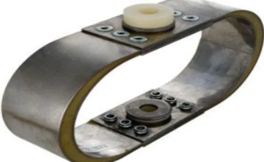
Fig 2: Elliptic Leaf Spring Mounts from Advanced Anti-vibration Components. The static loads for these springs range from 10 to 500 Kg per mount and have a natural frequency of 5~10 Hz (vibrationmounts.com).
V. LITERATURE REVIEW
Mohammed MathenullaSharif, N. SreenivasaBabu, Dr. JaithirthaRao[1]
The aim of this paper is to design and analyze composite mono leaf spring of constant width and thickness having the same bending stiffness of semi-elliptical laminated leaf spring. Stress analysis was done by using analytical method and results obtained by analytical methods are compared with ansys. The results obtained by analytical methods showed good agreement with ansys results.
T. Bhanuprasad, A Purushotham[2]
If number of layers are increased for same thickness the vibrations are less. In this paper we are concluding that using composite S - Glass Epoxy is advantageous. The major disadvantages of composite leaf spring are the matrix material has low chipping resistance when it is subjected to poor road environments which may break some fibers in the lower portion of the spring. This may result in a loss of capability to share flexural stiffness. But this depends on the condition of the road.
Ghodake A.P., Patil K.N[3]
This paper describes design and FEA analysis of composite leaf spring made of glass fibre reinforced polymer. The dimensions of an existing conventional steel leaf spring of a light commercial vehicle are taken for evaluation of results. The 3-D modeling of both steel and composite leaf spring is done and analyzed A comparative study has been made between composite and steel leaf spring with respect to Deflection , strain energy and stresses.
Vijaya Lakshmi, I. Satyanarayana[4]
The objective of this paper is to compare the load carrying capacity, stiffness and weight savings of composite leaf spring with that of steel leaf spring. The design constraints are stresses and deflections. The dimensions of an existing
conventional steel leaf spring of a Heavy commercial vehicle are taken Same dimensions of conventional leaf spring are used to fabricate composite multi leaf spring using material unidirectional laminates. Pro/Engineer software is used for modeling and COSMOS is used for analysis. Static & Dynamic analysis of Leaf spring is performed using COSMOS.
Edward Nikhil Karlus, Rakesh L. Himte, Ram Krishna Rathore[5]
The automotive manufacturer tends to enhance soothe of user and achieve appropriate stability of comfort riding virtues and economy. The researchers are very fascinated in the replacement of steel leaf spring by some composite leaf spring because of high strength to weight ratio. On the other hand, there is a restriction for the amount of applied loads in springs. The amplification in applied load creates complexity at geometrical arrangement of vehicle height and erodes other parts of vehicle.
S. Rajesh, G.B. Bhaskar[6]
A three layer parabolic leaf spring of EN45 has been taken for his work. The CAD modeling of parabolic leaf spring has been done in CATIA V5 and analysis was done by ANSYS -11. The finite element analysis (FEA) of the leaf spring was carried out initially discretizing the model into finite number of elements and the nodes by applying the boundary conditions.
R D V Prasad , P.Venkatarao, P.Venkatarao[7]
Leaf Spring is a critical load bearing element that connects wheel to the chasis in an automobile application. The Suspension leaf spring of one of the potential items for weight reduction in automobiles in order to achieve increased fuel efficiency and improved ride characteristics. The introduction of fiber reinforced plastics (FRP) made it possible to reduce weight of the product without any reduction in load carrying capacity and stiffness.
M. Raghavedra , Syed AltafHussain, K. PalaniKumar[8] This paper describes design and analysis of laminated composite mono leaf spring. Weight reduction is now the main issue in automobile industries. In the present work, the dimensions of an existing mono steel leaf spring of a Maruti 800 passenger vehicle is taken for modeling and analysis of a laminated composite mono leaf spring with three different composite materials namely, E-glass/Epoxy, S-glass/Epoxy and Carbon/Epoxy subjected to the same load as that of a steel spring.
Spring Mounts – Elliptic Leaf Type (Naval "X" Type)[9] This type of vibration and shock isolator was designed specifically for shipboard or mobile applications. They are
particularly suitable to protect delicate shipboard equipment from shock due to underwater explosions or sudden stoppage of vehicles for vehicle-mounted equipment.
VI. OBJECTIVE
1) Design and development of elliptical spring mounts for 2-stroke Petrol 35 cc petrol engine.
2) Fabrication of elliptical spring mounts from spring steel (EN 48D) and SS-304 material
3) Testing of the developed elliptical spring mounts of EN 48D & with SS-304 material on the 35 CC engine to determine the Overall damping coefficient & RMS values for respective springs
4) Comparative analysis of the performance of the engine with both damper systems as to vibration parameters and recommendation of application for each spring .
VII. METHODOLOGY
1. In all cases forces are the source of vibration. This leads to the three basic methods to control vibration:
2. Control the magnitude of the vibrating forces. Examples are the balancing unit on a grinder or the differential piston in a chipping hammer.
3. Make the tool less sensitive to the vibrating forces. Examples can be when the mass of the guard on a grinder is rigidly connected to the tool to increase the inertia of the tool. 4. Isolate the vibrations in the tool from the grip surfaces. Examples are vibration dampening handles on grinders or pavement breakers, the air-spring behind the blow mechanism in a riveting hammer or the mass spring system in a chipping hammer.
5. In our approach to design we have adopted the third method of isolating the vibrations in the tool from the grip surface using elliptical leaf spring mounts
VIII. WORKING STEPS
Typical working steps involved in the proposed work are mentioned as below
Step 1: Literature Review
In this phase literature survey of damper systems, hand held power agriculture machinery vibrations etc. will be carried out by referring journal like SAE journal, International papers, European patents ,US patents etc. Step 2: System design & Mechanical design of the elliptical leaf spring mounts for engine of following specifications Prime mover selection Make: Crompton Greave Model: IK-35
Engine is Two stroke Spark ignition engine with following specifications:
Stroke: 35 mm Capacity: 34 cc
Power out pu : 1.2 BHP at 5500 rpm Torque: 1.36 N-m @ 5000 rpm Dry weight: 4.3 kg
Ignition: Magneto ignition
Direction of rotation: Clockwise .looking from driving end Carburetor: ‟B‟ type
Cooling: Air Cooled engine
Step 3: Mathematical model development of system for elliptical spring mount configuration
Step 4: Selection of materials of spring mount to sustain the vibrations, justification as to selection of EN48 D and SS304 as spring materials
Step 5: System design for mechanical component like the engine connection, Main rubber bracket, coupler bracket Leaf profile geometry, Number of leaf springs, chassis connection for given system of operation. This phase includes the planning of system as per the sketch above Step 6: Mechanical design of all components of the set up using theoretical formulae .for mechanical component engine connection , Main rubber bracket , De-coupler chamber coupler bracket, chassis connection rod, damper head, mount shaft etc for given system of forces
Step 7: 3-D modeling of set-up using Unigraphix.
Step 8: CAE of critical component and meshing using Hypermesh /Ansys.
Step 9: Mechanical design validation using ANSYS …critical components of the system will be designed and validated
Step 10: Validation of strength calculations of critical components viz, engine connection , Main rubber bracket , De- coupler bracket, mounting shaft , Compensation chamber , chassis connection rod , damper head , mount shaft using ANSYS.
Step 11: Results and Discussion based on experimentation. Testing of the developed system with and without the elliptical spring mounts to determine the Overall damping coefficient & RMS values at two operating speeds. The values will be determined using a graphical method by plotting the amplitude and frequency of vibration and Comparative analysis of the performance of the system with elliptical spring mounts made from EN48D & SS 304 materials
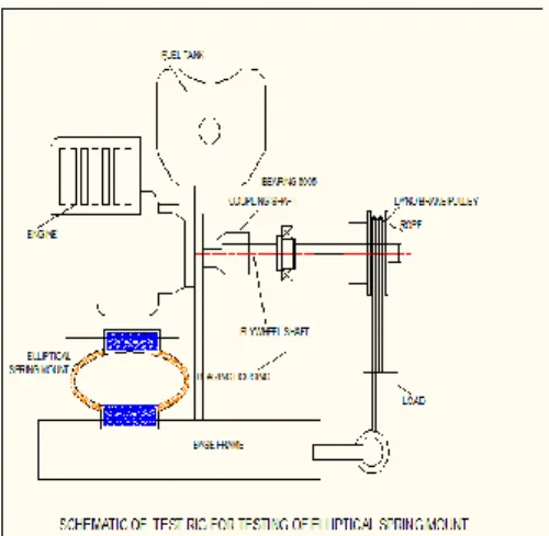
Fig 3: Test Rig For Elliptic Leaf Spring Mount
IX. PROCEDURE FOR DESIGN &TESTING
Set up consist of agriculture sprayer using two stroke petrol engine coupled to a interchangeable conventional spring mount / Composite half elliptical leaf spring engine isolation mount. Load cell is connected to the engine that will determine the vibrations reduced terms of value of load displayed on the load cell display. A suitable arrangement will be added to log the data of load after predetermined number of cycles. The data thus obtained will be processed to determine the nature and extent vibration reduction for each case of rubber mount / Composite half elliptical leaf spring engine isolation mount for ¼ , ½ , ¾ & full throttle openings
IX. PROCEDURE: 1) Start engine by turning
2) Let mechanism run & stabilize at certain speed (say 1300 rpm)
3) Place the pulley cord on dynamo brake pulley and add 100 gm weight into , the pan , note down the out put speed for this load by means of tachometer.
4) Add another 100 gm cut & take reading of vibration amplitude and frequency by graph and stylus method. 5) Tabulate the readings in the observation table 6) Plot amplitude Vs speed characteristic Frequency Vs speed characteristics
X. EXPECTED OUTCOME OF THE PROJECT-
Testing of the developed system with and without the elliptical spring mounts to determine the Overall damping coefficient & RMS values at two operating speeds. The values will be determined using a graphical method by
plotting the amplitude and frequency of vibration and thereby derivation of ahw in m/s2 where (h means hand transmitted and w means weighted) Comparative analysis of the performance of the system with elliptical spring mounts made from EN48D & SS 304 materials
XI. SCOPE
3-D modeling of set-up using Unigraphix Nx-8.0 CAE of critical component and meshing using Ansys --ie the preprocessing of part. Mechanical design validation using ANSYS …critical components of the system will be designed and validated. Validation of strength calculations of critical components viz, drive eccentric crank , connecting rod , damper piston , orifice plate etc using ANSYS. i.e the post processing part. Testing of the developed system with and without the elliptical spring mounts to determine the Overall damping coefficient & RMS values at two operating speeds. The values will be determined using a graphical method by plotting the amplitude and frequency of vibration and thereby derivation of ahw in m/s2 where (h means hand transmitted and w means weighted) .Comparative analysis of the performance of the system with elliptical spring mounts made from EN48D & SS 304 materials .Conclusion will be drawn on the basis of theoretical and experimental results.
REFERENCES
1) Mohammed MathenullaShariff ,N. SreenivasaBabu, Dr. JaithirthaRao “Analysis of Glass Epoxy Reinforced Monolithic Leaf Spring” International OPEN ACCESS Journal Of Modern Engineering Research (IJMER), ISSN: 2249–6645 , Vol. 4, Iss. 8, pp-Aug. 2014
2)T. Bhanuprasad, A Purushotham “Performance Comparative Analysis of S-Glass Epoxy Composite leaf spring with M. S. LEAF SPRING” IOSR Journal of Mechanical and Civil Engineering (IOSR-JMCE) ,Volume 10, Issue 4, pp-38-41, Nov. - Dec. 2013.
3) Ghodake A.P., Patil K.N. “Analysis of Steel and Composite Leaf Spring for Vehicle” IOSR Journal of Mechanical and Civil Engineering (IOSR-JMCE), Volume 5, Issue 4 , pp 68-76, Jan. - Feb. 2013
4) B. Vijaya Lakshmi, I. Satyanarayana “ Static And Dynamic Analysis On Composite Leaf spring In Heavy Vehicle” International Journal of Advanced Engineering Research and Studies, (IJAERS) Vol.II, ISSN2249–8974, pp-80-84E, Oct.-Dec., 2012.
5) Edward Nikhil Karlus, Rakesh L. Himte, Ram Krishna Rathore “Optimization Of Mono Parabolic Leaf Spring” International Journal of Advances in Engineering & Technology, Vol. 7, Issue 1, pp 283-291 ISSN- 22311963, Mar. 2014
6) S. Rajesh, S. Nakkeran , G.B. Bhaskar “ A Survey of GFRP Composite leaf spring” International Journal of Engineering & Technology, pp.135-193, Feb-2014. 7) R D V Prasad1, R.SaiSrinu , P.Venkatarao “Design & Analysis of Mono Composite Leaf Spring” International Journal of Scientific Research Engineering & Technology (IJSRET) , Volume 2, Issue2, pp 103-107, May2013 . 8) Mr. Anandkumar A. Satpute Prof. S. S. Chavan “Mono Composite Leaf Spring – Design and Testing” Volume - 3, ISSN - 2249-555X , July 2013.
9) Spring Mounts – Elliptic Leaf Type (Naval " X " Type)” Rev: 9-11-07 SS, www.vibrationmounts.com
AUTHOR PROFILE
Sandip S. Nehe received the D.M.E. and B.E. degrees in
Mechanical Engineering from Amrutvahini College of Engineering by MSBTE & Pune University in 2010 and 2013, respectively and appear in M.E. degree in Design Engineering from Sahyadri Valley College of Engineering, Junnar by Pune university in 2015.