PRODUCT DESCRIPTION
The PREZONE2 is a professional audio device designed to accept audio signals from multiple sources and supply two distinct zones of audio outputs from these sources. The device may be controlled from the front panel user interface, wall control panels, Ethernet capable devices with a web browser, or an external control system using RS232 or TCP.
FEATURES
• Emergency Input • 2 Mono Mic/Line Inputs • 2 Stereo Output Zones• 2 Zone Selective Paging Input with Chime • 4 Stereo Line Inputs
• Wall Panel Control • Auto Standby • Ethernet and RS232 • Control Priority Output
• Includes Adhesive Labels for Zone & Source Identification • Webapp Control
• CE marked, UL listed and RoHS compliant
IMPORTANT SAFETY / COMPLIANCE INFO
Class 2 wiring: to reduce the risk of electric shock, the external wiring connected to the terminals marked with “class 2 wiring” requires installation of class 2 wiring by an authorized/trained person or by using ready-made leads or cords.
This unit has NOT been designed for use in mobile applications, such as: mobile discobars, mobile PA systems, live bands and audio rental systems. Using it in such applications will lead to product damage and safety risks. Do not remove or defeat the ground prong on the power cord, as this will constitute a shock hazard. Equipment should be connected to a mains socket outlet with a protective earthing connection. This plug is the main disconnecting device and should remain readily operable. There are no user interchangeable parts. Please contact Biamp Technical Support or your local distributor for all service requirements.
Further safety and compliance information may be found at:
www.biamp.com/compliance
Warranty information may be found at:
www.biamp.com/legal/warranty-information
PREZONE2
5. Zone 2 Volume Control
Rotary volume controls and mute button for microphones A/B in Zone 2 6. LED Status Indicators
LED DESCRIPTION GREEN ORANGE RED
S/C Z1 Zone 1 Signal Present/
Clip Signal Present N/A Clipping Condition Present S/C Z2 Zone 2 Signal Present/
Clip Signal Present N/A Clipping Condition Present
EMG Emergency Mode N/A Active N/A
PAG Paging Mode Active N/A N/A
VOX Mic A VOX Override
Active Active N/A N/A
PREZONE2 FRONT PANEL
12
3 4
5
PREZONE2 Front Panel Controls
The PREZONE2 front panel features a power/standby button, controls for two distinct zones of audio outputs and an array of LEDs that give status of numerous functions of the device. Rotary encoders (volume controls) feature LED indication of the actual volume level. Adhesive labels may be applied to indicate zone sources and outputs.
1. Standby
Initiates or disables manual standby mode. Indicates status of standby mode. 2. Zone 1 Volume Control
Rotary volume controls and mute button for microphones A/B in Zone 1 3. Zone 1 Input Source Selection & Volume Control
Rotary volume control for 4 audio input source selection in Zone 1. User-defined labels for audio source and output.
4. Zone 2 Input Source Selection & Volume Control
Rotary volume control for 4 audio input source selection in Zone 2. User-defined labels for audio source and output.
PREZONE2 BACK PANEL
PREZONE2 Back Panel Connections
The back panel features numerous inputs and outputs as well as equalizers for both zones, connections for wall controllers, Ethernet and RS232. All inputs are designated by priority level (1 - 4). For specific instructions on controls, connections and wiring, see "Back Panel Wiring and Connections" on page 5.
1. Emergency Input
The Emergency Input has the highest priority level of the inputs and will mute all other audio when active.
When the emergency mode is active, it is indicated by the front panel LED (EMG), the EMG indicator on the webapp and a RS232 or Ethernet notification. Activating the emergency input will disable standby mode and activate the priority output for both zones.
The emergency input may be activated by a contact closure or an audio signal that exceeds the VOX threshold level. If an audio signal is applied and VOX mode active, it will also be sent to both audio zones.
2. Paging Mic Input
The Paging Mic input has the 2nd highest priority of all inputs. Paging is zone-specific and each zone may be paged independently or simultaneously. Paging overrides all audio in the active zones except the Emergency Input.
A paging chime may be set to activate prior to the paging mic being active. Paging mic status is indicated by front panel LED (PAG), the PAG indicator on the webapp and a RS232 notification. Activating the paging mode will also activate the priority output of the selected zone(s).
3. MIC A Input
MIC A input has the 3rd highest* priority of all inputs. The input connection accepts a balanced microphone or line level audio signal via the Euroblock connector and a stereo line level via RCA connectors. A pushbutton allows switching between MIC and LINE (Euroblock).
NOTE: MIC A priority level may be disabled by turning the VOX level to the OFF position. If disabled, MIC A is summed with the MIC B / Line Inputs.
The RCA input is stereo, but a mono sum will be fed to the stereo zone output. GAIN and HI LO EQ may be adjusted via control knobs. An LED indicates any clipping condition.
Phantom power (48 V) may be applied to the balanced Euroblock via the phantom power pushbutton switch.
VOX, when activated, will attenuate all lower priority sources (MIC B and Inputs 1-4) by 30 dB.
4. MIC B Input
MIC B input has the 4th (lowest) priority of all inputs. The input connection accepts a balanced microphone or line level audio signal via the Euroblock connector and a stereo line level via RCA connectors. A pushbutton allows switching between MIC and LINE (Euroblock).
The RCA input is stereo, but a mono sum will be fed to the stereo zone output. GAIN and HI LO EQ may be adjusted via control knobs. An LED indicates any clipping condition.
Phantom power (48 V) may be applied to the balanced Euroblock via the phantom power pushbutton switch.
1 2 3 5 10 14 6 4 7 9 11 13 12 8
5. Input 1
The input connection accepts a stereo balanced line or line level audio signal via the Euroblock connector and a stereo line level via RCA connectors.
Gain may be adjusted via a control knob. An LED indicates any clipping condition. Both input connections may be used at the same time and will be summed together.
6. Input 2-4
These input connections accept stereo inputs using unbalanced RCA connectors. Gain may be adjusted via a control knob. An LED indicates any clipping condition. 7. Zone 1&2 EQ
Audio equalization (HI and LO tone controls) for Zone 1 and 2 outputs. 8. Zone 1&2 OUT
Stereo audio output for zones 1 and 2. The mono/stereo switch allows the output to be configured as a mono or stereo output. Balanced Euroblock and unbalanced RCA connectors are available and active at the same time.
9. Wall Control
Allows connecting two DIWAC or D-DIWAC wall panels, one for each zone, to allow control of source selection and volume control for each zone.
10. Ethernet
RJ45 connector that allows Ethernet access, control and configuration. This may be connected to a network or an individual device using standard CAT5e (or better) cable.
11. Auto Standby
Enables/Disables auto standby mode. 12. Priority Out
3-pin Euroblock connector with two 24 VDC priority signals. Active when either the Emergency Input or Paging is active to the zone connected. Overrides external volume controls present on speaker lines so emergency or paging messages are audible, regardless of physical volume control status.
13. RS232
3-Pin Euroblock connector that allows the PREZONE2 to be controlled from an external device.
14. Main Power Input Switch & Fuse
3-prong mains power cord connection, power on/off switch and mains fuse (T1AL/250V glass tube).
Installation and Connections
The PREZONE2 may be rack-mounted (requires 2RU of rackspace) or placed on a flat surface to meet design/space requirements as needed.
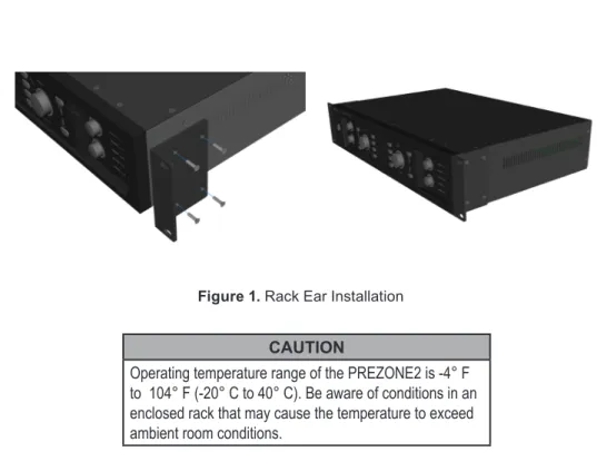
For rack-mounting, the PREZONE2 comes with two removable rack-ears (Figure 1).
For surface mounting, the PREZONE2 is equipped with removable rubber feet.
When installing in a rack, always install the lower attachment hardware first to
avoid damaging equipment.
CAUTION
Operating temperature range of the PREZONE2 is -4° F to 104° F (-20° C to 40° C). Be aware of conditions in an enclosed rack that may cause the temperature to exceed ambient room conditions.
NOTE: When installing in a rack space, leaving a 1/2 rack gap at top and bottom of the unit will help ensure adequate ventilation and prevent overheating.
6. If the Chime level is set to OFF, the paging mic will be live immediately upon activation. Otherwise the chime will play in the selected zone(s) at the volume set prior to the mic going live.
Wiring - MICPAT-2 & MICPAT-D to Paging Mic Input
If connecting a MICPAT-2 paging station to a PREZONE2, users may send paging messages to both zones, either together or independently.
MICPAT-2 Wiring
1. Connect the MICPAT-2 to the PREZONE2 as shown in Figure 4a. 2. The MIC/LINE switch is typically set to LINE, however it may be set to
MIC for greater sensitivity, but take care to avoid clipping.
If connecting a MICPAT-D paging station to a PREZONE2, users may send paging messages to both zones together.
MICPAT-D Wiring
1. Connect the MICPAT-D to the PREZONE2 as shown in Figure 4b. 2. The MIC/LINE switch is typically set to LINE, however it may be set to
MIC for greater sensitivity, but take care to avoid clipping.
NOTE: Refer to the appropriate MICPAT manual for further details on set up and use of the paging stations.
Back Panel Wiring and Connections
The section that follows gives information about wiring/connecting and operation of select inputs and outputs on the back panel.
Wiring - Emergency Input
1. See Figure 2. Connect a balanced 0 dBV line level emergency input audio signal to the Euroblock connector.
2. If available, connect the emergency contact to the “mute all” connection. The contact must be “potential free” (a relay or switch contact that does not carry any voltage.)
3. Alternatively, activate the VOX circuitry by turning the VOX control until there is an audible “click”. 4. Turn the VOX control up while playing music until
the VOX circuit is activated. The VOX and the 'mute all' switch have the same function: they will mute all other sources and "wake" the unit from standby (auto standby and manual button standby). 5. The emergency level can be set with the volume control.
6. Lower the level of the emergency signal at the source to avoid distortion if the clip LED illuminates when the emergency signal is present.
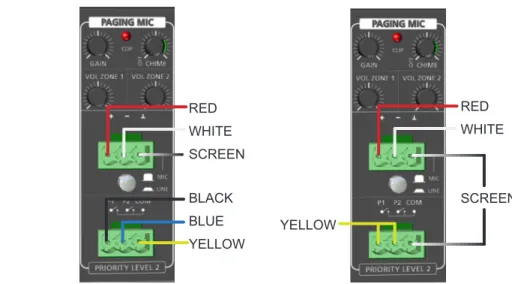
Wiring - Paging Mic Input
1. See Figure 3. Connect the microphone - the Euroblock accepts balanced microphone or line level signals.
2. Set the MIC / LINE switch accordingly.
3. Adjust the gain control so the clip LED does not illuminate when the signal is at the highest level. 4. Adjust zone volume controls as required.
5. When paging is active, all other sources except Emergency Input are muted.
Figure 2. Emergency In
Figure 3. Paging Mic
RED WHITE SCREEN BLACK BLUE YELLOW
Figure 4a. MICPAT-2 Wiring
RED WHITE
SCREEN YELLOW
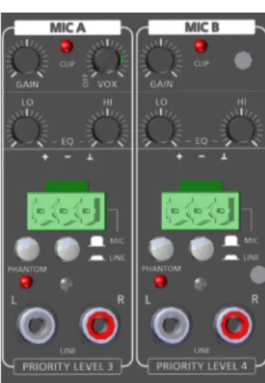
Wiring - MIC A Input/MIC B Input
1. See Figure 5. Connect the microphone - the Euroblock accepts balanced microphone or line level signals; the RCA jacks accept line level signals. 2. Set the MIC/LINE switch accordingly.
NOTE: if the balanced input is left open, LINE should be selected to eliminate input noise.
3. The stereo unbalanced input signals are mono, summed and merged with the balanced input into one signal which may be sent to all zone outputs. 4. Phantom power (48 V) may be applied to the balanced Euroblock by
pushing the phantom power switch.
5. Adjust the gain control so the clip LED does not illuminate when the signal is at the highest level.
6. Adjust EQ as needed.
7. If necessary, activate the VOX circuitry by turning the VOX level control until there is an audible “click” (MIC A Input only).
8. When activated, the VOX circuit will attenuate all lower priority sources (MIC B, Input 1-4) by 30 dB in the zone(s) where MIC A is enabled. 9. Volume may be set using the front panel level control. MIC Input A or B
may be activated by pressing the respective MIC A or B select switch on the front panel.
Wiring - Inputs 1-4
1. See Figure 6. Connect source inputs as required. Input 1 has Euroblock connectors that
accept balanced line level signals and RCA jacks that accept line level signals. Inputs 2-4 accept RCA only.
NOTE: the balanced and unbalanced signals are summed, while keeping the stereo signal. Both inputs (Input 1) may be used at the same time.
2. Adjust the gain control so the clip LEDs do not illuminate when the signal is at the highest level.
Wiring and EQ - Zones 1 and 2
1. See Figure 7. Connect stereo outputs to either the balanced
Euroblock or unbalanced RCA connectors for Zones 1 or 2. Stereo or Mono may be selected.
2. LO and HI tone controls may be adjusted via EQ knobs for either zone.
Figure 6. Inputs 1 - 4
Figure 7. Zone Outputs & EQ Figure 5. Mic A & B
Figure 8. Wall Control & Ethernet
Back Panel Wiring and Connections (continued)
Wiring - D-DIWAC and DIWAC Wall Controls
1. The PREZONE2 is compatible with the D-DIWAC and DIWAC wall controls. Connect wall controls from the appropriate zones via connectors on the back panel as shown in Figure 8.
2. The maximum cable length per wall control is 1640 ft. (500m) using CAT6 cable (half the conductors used at each pin of the connector) or 16 AWG, 2 Conductor (16/2) loudspeaker cable.
3. Volume and audio source selection may be controlled
independently for Zones 1 and 2 via the wall controllers. Only one wall control panel may be connected per
zone.
NOTE: Data and power are carried across both wire
connections, therefore there is no specific polarity on the
2-pin Euroblock connectors. Wiring - Ethernet
1. See Figure 8. Connect the PREZONE2 to a network via a router or directly to an individual device with CAT5e or better cable.
2. Once connected, users have several options to access a fully-responsive webapp to operate the PREZONE2. See "Network Connections" for more
information on network configuration and
accessing the webapp control page.
Wiring - Priority Out
1. See Figure 9. Connect the 3-pin Euroblock to the override relay in any in-line volume controls wired in the loudspeaker line for Zones 1 and/or 2, as required.
2. These signals will become active when either the emergency system or paging is active to the zone controlled.
3. A priority signal overrides the external volume control so emergency/paging messages are heard, regardless of the physical state of the volume control. NOTE: Do not use the priority output continually at full power.
Wiring - RS232
1. See Figure 9. Connect an external device to the PREZONE2 via the RS232 connection. RS232 serves as a text command interface with the following port parameters:
• baud rate: 115200 • 8 data bits
• 1 stop bit • no parity
2. See "RS232 Control" for more information on using text command protocol with the PREZONE2.
Figure 9. Priority Out & RS232
Back Panel Wiring and Connections (continued) Standby Modes
The PREZONE2 has two standby modes: Manual and Auto.
Manual Standby Mode
If auto standby is set to DISABLED on the back panel, push the on/standby button to enter standby mode. When in standby mode, the front panel on/ standby button will pulse. The webapp will indicate the device is in standby mode and the displays of any connected DIWAC wall panels will turn off. The device will exit standby mode if:
• Any front panel button is pushed • Emergency Mode is activated • The back power switch is cycled
on/off (or mains power is otherwise interrupted)
NOTE: the device will enter standby mode by pushing the front panel standby button, regardless of the auto standby setting. Auto Standby Mode
See Figure 10. If auto standby is set to ENABLED on the back panel, the PREZONE2 will enter standby if no audio is present (less than -40dB) on all selected inputs for 10 minutes. The device will not enter standby if Emergency or Paging modes are active.
When auto standby is active, the front panel On/Standby button LED will pulse on and off. Any connected DIWAC wall panels will indicate that auto standby is active as will the webapp.
The device will exit auto standby mode if:
• An audio signal above -40dB is applied to a previously-selected input • Any front panel button is pushed (including the On/Standby button) • A connected DIWAC wall panel button is pushed
• Emergency or Paging Mode is activated
• The back power switch is cycled on/off (or mains power is interrupted) • An external SET command is received via RS232 or TCP
• Webapp is accessed
Network Connections
The PREZONE2 may be operated via the built-in webapp or text commands by connecting the PREZONE2 to a controlling device via a network connection. The PREZONE2 will automatically obtain an IP address and configure. In a routed network, the PREZONE2 will obtain an IP address via DHCP. In a switch network or direct connection to a controlling device, the PREZONE2 will auto-generate a link-local address. A manual IP may also be set.
Factory default hostname is 'prezone2,' which may be changed in the webapp (connecting via hostname is the most reliable way to connect to the PREZONE2) Further information on PREZONE2 connections and Zero Network Configurations can be found on support.biamp.com.
Connect to the Webapp via Switched or Routed Network
The PREZONE2 webapp may be accessed via PC/Laptop or mobile device, depending on the network configuration. PREZONE2 uses a standard called ‘Zero Configuration Networking,’ which allows the device to fully configure itself.
1. See Figures 11-13 for connection options. Use the configuration suitable
to design and network requirements.
2. Once the PREZONE2 is connected in one of the configurations shown,
open a web browser on a PC or mobile device and enter the hostname in the address bar.
a. Regardless of the connection type (wired/wireless), the controlling device must be on the same network infrastructure as the PREZONE2. 3. If a DNS server is available, enter the hostname in the browser as follows:
"prezone2/". Press enter.
4. If no DNS server is available or the PREZONE2 is connected to a switched network, use mDNS to connect by entering the hostname in the browser bar as follows: "prezone2.local/". Press enter.
5. Another option to connect is by entering the IP address directly into the
browser bar (use of a 3rd party application can be used to find the IP
address).
6. The PREZONE2 webapp will now be available via the connected device. Multiple devices may connect to the PREZONE2 simultaneously.
NOTE: Android devices do not allow ".local" searches from the browser. If using an Android device, use a local DNS server to resolve the hostname to the IP address. If no DNS server is available, enter the IP address directly into the web browser bar.
Network Diagrams
The following diagrams give basic information about network connections.
Figure 11 shows a direct Ethernet connection from the PREZONE2 through the router to a PC. PREZONE2 will auto-configure and automatically obtain an IP address.
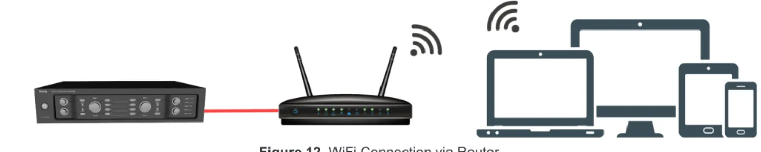
Figure 12 shows a direct connection from the PREZONE2 through the router and wireless connections of various devices. PREZONE2 will auto-configure and automatically obtain an IP address.
Figure 13 shows a direct connection from the PREZONE2 to a PC via Ethernet. This connection does not require any manual IP settings (link-local - both devices auto negotiate).
Figure 13. Direct Ethernet Connection Figure 11. Direct Ethernet Connection via Router
PREZONE2 Webapp
Once the PREZONE2 is connected to a network and is accessible via PC or mobile device, the webapp may be used to control features and functions of the PREZONE2.The primary components of the webapp are the control page and the settings page.
The table that follows gives device, operating system and browser combinations that have been tested and are supported. Other configurations not listed here are likely to function properly but have not been tested.
Device Operating System Web Browser
Windows PC Windows 7 & 10 Chrome & Firefox Android phone & tablet Android 8, 9 & 10 Chrome & Firefox iPhone, iPad & iPad Pro iOS 12 & 13 Chrome & Safari Note: Microsoft Edge is currently not supported.
Webapp Passwords
The Webapp may be password-protected in two locations (with different passwords) to allow different access levels to users. Both the Control Page and the Settings page may be password-protected. It is also permissible to set a password for either, both or none. This allows an administrator allow or limit access to certain functions of the PREZONE2, which are detailed in the sections that follow.
By default, no passwords are set. Control Page
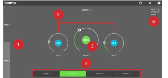
The Control page provides Zone, MIC and Source controls as well as status indications such as clipping, paging and emergency mode status. The Control Page may be password-protected.
See Figure 14 on the following page for an example of the Control page
1. Zone Selection Tabs
The zone selection tabs enable control of either Zone 1 or 2. Both zone tabs have controls for mic volume, source selection and volume and give status of clipping, paging and emergency mode status.
2. MIC A and B Controls
The MIC A and B rotary dials control the level of the respective microphone input of the zone selected. The loudspeaker icon in the middle of the dial turns the microphone on or off.
3. Line Level Control
This rotary level control adjusts the volume of the selected source. The loudspeaker icon in the middle of the dial turns the source audio on or off. 4. Line Source Selection
Allows selecting the input for the current zone; only one source may be selected at a time.
5. Power, Night Mode and Settings
• Power Button - puts the PREZONE2 in Standby Mode.
• Night Mode - changes the color scheme so the PREZONE2 display is more suitable (dimmer) for dark locations (Fig. 14 shows Night Mode). • Settings - enters the settings page. See "Settings Page" for information.
Figure 14. Webapp Settings Page 1 2 3 4 6 5
PREZONE2 Webapp - Control Page (continued)
6. Status Indicators
• Signal / Clip - illuminated green when a signal is present; illuminated red when the signal is clipping in the selected zone.
• Paging - illuminated green when a paging announcement is active in the selected zone.
• Emergency - illuminated green when emergency mode is active LEDs on the front panel will reflect the level, selection and status in the webapp and vice-versa. For example, when adjusting the volume control for Zone 1 in the webapp, the LED around the Zone 1 knob will adjust accordingly.
Control Page Password
The Control Page password may be set from the Settings Page. If created, all users will be required to enter a password to access the controls listed above. Settings Page
The Settings page is accessed by clicking the gear icon at the top of the Control page. Users are presented with the screen shown in Figure 15.
1. Device Info
• Gives general device information like device name, hostname, IP address, software version, serial number and MAC address. 2. Labels
• Allows editing the names of each zone, microphone or input from their default value. Letters, numbers, hyphens and spaces are allowed (ASCII character set).
3. IP
• Allows toggling between automatic and manual IP modes. See IP Mode section later in this document for more information.
4. Hostname
• Allows changing the hostname by changing the device name. Note that identical hostnames on a local network are not allowed; if a conflict is present, the hostname will automatically be appended with '-a' or '-b' etc., until the conflict is resolved. Therefore it is possible the device name and hostname may not match.
5. Volume Limits
• Allows adjusting minimum and maximum level controls for MIC A, MIC B and Line music levels for each zone via a volume limit slider. There must be a minimum 10% difference between the minimum and maximum volume levels.
6. Passwords
• Passwords can be created for both the Settings panel and Control page to limit access to PREZONE2. An admin may choose to restrict access to either or both of these interfaces depending on the specific requirements or preferences of the organization, administrator, etc. 7. Factory Reset
• This allows a full factory reset of the device. All settings will be erased and returned to the factory default settings and the device will automatically restart when performing a factory reset.
NOTE: A factory reset may also accomplished via RS232 or TCP/IP command and a button sequence. See Factory Reset in the section that follows for more information.
PREZONE2 Webapp - Settings Page (continued) Factory Reset
Resetting the PREZONE2 to its factory default settings may be accomplished via the webapp as described previously, an RS232 or TCP/IP command, or by the button sequence that follows:
Power on the device while holding the following buttons: • MIC A Selection Zone 1
• MIC B Selection Zone 1 • Front Standby Button
A factory reset will occur when the buttons are released (the device will reboot).
RS232 Control
The RS232 control port allows controlling the PREZONE2 via an external device using text command protocol.
The protocol uses SET and GET as the first part of the command structure. SET may be used to change values in the device while GET may be used to gather information about the device.
GET and SET must be followed by details of the items to be controlled or queried. Basic rules and tips for successful RS232 communication are below. <CR> indicates a carriage return. <LF> indicates a line feed.
• A valid command is always answered with Ok <CR> <LF> • An invalid command is always answered with Error <CR> <LF>
• All commands must end with <CR>, <LF> or <CR> <LF> depending on the controlling device and program being used.
• Only ASCII characters are allowed (UTF-8 is not supported). • Keywords are not case-sensitive.
• The commanding device must wait for a response (Ok <CR> <LF> or Error <CR> <LF>) before sending a command that changes the same setting.
TCP/IP Control
The PREZONE2 may also be controlled via TCP/IP; the unit will listen for TCP commands on port 4999.
TCP command structure is similar to RS232 as covered in the previous section.
Some differences and functions unique to TCP are covered in the paragraphs that follow.
• Each TCP packet may contain a single or multiple commands.
• A total of four simultaneous hosts are allowed; attempting to connect a fifth host will be denied.
• The PREZONE2 will combine text as much as possible in responses. • The command 'set factory reset' is executed immediately.
• Sending the same GET command numerous times in one packet will only result in one notification.
• Sending the same SET command numerous times in one packet will only result in one notification. Each set command will get its corresponding Ok, yet the notification will only show the latest state of the last command. Note that sending a command of 'set ip mode' that changes the current setting will result in no response to the host device as the connection will be closed (all Ethernet connections are closed if changing the IP address). If 'set ip mode' is included with other commands, all commands in the packet will be executed prior to the 'set ip mode' command.
Text Command Examples
Text Command Action/Response
set zone 2 selected input 3 <CR><LF> Selects a source in Zone 2 set zone 1 input volume 60 <CR><LF> Changes the audio level in Zone 1 set zone all mica inc volume 5
<CR><LF> Increments the MIC A level in both zones get zone 2 micb onoff <CR><LF> Checks the status of MIC B in Zone 2. Response
will indicate if the mic is on or off.
get system info <CR><LF> Gets all settings of the PREZONE2. Response will be a list of all current device settings and other info.
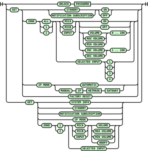
Figure 16. RS232 and TCP Text Command Diagram
Figure 16 gives possible text commands. By following the connections from the left to right, valid commands may be created.
Note that although the commands in Figure 16 will work for RS232 and TCP/IP, the structure is designed for RS232.
RS232 & TCP Notifications
Once a connection is made, the host is subscribed to all notifications. An unsubscribe command will stop notifications as will a lost connection or if the unit is power-cycled. When unsubscribing, an 'Ok' and 'Error' message will follow.
External devices will receive PREZONE2 state notifications via RS232 &TCP.
If a device parameter changes, a message will be sent out over RS232 to the external device. This can be a volume update or a signal / clip LED change. These notifications are normal ASCII text and are similar to the text commands except they do not contain the SET or GET keyword. All notifications will end with <CR> <LF>.
Using the notifications is highly recommended over polling the PREZONE2 from the external device via get messages.
Password Protection
If a password is created for the Webapp settings, the TCP text command interface will be password-protected as well. A new, 'out of the box' PREZONE2 will not have a password set, therefore the TCP interface is unlocked by default.
If a password is set in the Webapp settings:
• Any open TCP connections will be locked and the following notification sent: "PREZONE2 is locked <CR> <LF>".
• New connections will open in a locked state and must be unlocked to be used. • Connections may be unlocked with the command "unlock password <CR>
<LF>".
• Successful unlocking of the PREZONE2 will result in the following response: "PREZONE2 is unlocked <CR> <LF>".
• Any commands sent to the unit in a locked state will result in "PREZONE2 is locked <CR> <LF>".
If a connection is locked, it will be closed after three minutes if not unlocked via the previously mentioned password-entry command. If attempting to open a fifth connection, this connection will take priority over any locked connections - the oldest locked connection will be closed and the new connection accepted if this is requested during the three-minute timeout period.
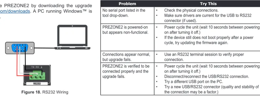
Figure 18. RS232 Wiring
Figure 19. Select Serial Port
IP Mode
The PREZONE2 allows users to manually configure an IP address. By default, the unit is set to discover an IP automatically with no configuration required. Users may change the IP Mode (Manual or Automatic) from three locations:
• Settings page of the Webapp • Text command interface • Sequence on startup
In Automatic mode, it is best to have the router set to always give the same IP address.
Setting the device to Manual IP mode will require the user set the IP, netmask and gateway (if no gateway is present, set it to 0.0.0.0).
From the webapp, the IP mode is changed in the Settings page. Text commands to change the IP mode are as follows:
• set ip mode automatic <CR> <LF>
• set ip mode manual <IP address> <Netmask> <Gateway> <CR> <LF> If the IP mode is set incorrectly, the PREZONE2 may be started in a special mode to reset the IP mode. Power the PREZONE2 on while holding all four Zone 1 input buttons to reset to Automatic IP mode.
Firmware Upgrade
Firmware may be updated on the PREZONE2 by downloading the upgrade package located on www.biamp.com/downloads. A PC running Windows™ is required (32 and 64 bit supported).
The PC must be connected to the PREZONE2 via the RS232 port on the back of the device. The user will need an RS232 connector (if the PC has an RS232 port) or a USB to RS232 connector. See Figure 18 for a connection diagram.
1. Click this link to automatically
run the firmware upgrade
tool.
2. Click Run to install the .exe file on the PC that will be connected to the
PREZONE2. A shortcut will be installed on the desktop by default. 3. Connect the PC to the PREZONE2 RS232 port via an appropriate
connector as shown in Figure 18. 4. Power on the PREZONE2.
5. Double-click the Firmware upgrade application on the PC.
6. Choose the serial port that the USB to RS232 is connected to as shown in Figure 19.
7. Click 'Connect' and follow the on-screen instructions.
8. Once the upgrade is complete, power down the PREZONE2 and disconnect the USB to RS232 connector.
Firmware Upgrade Troubleshooting
Common problems and solutions are listed in the table below.
Problem Try This
No serial port listed in the
tool drop-down. • • Check the physical connections. Make sure drivers are current for the USB to RS232 connector (if used).
PREZONE2 is powered-on
but appears non-functional. • Power cycle the unit (wait 10 seconds between powering on after turning it off.) • If the device still does not boot properly after a power
cycle, try updating the firmware again.
Connections appear normal,
but upgrade fails. • Use an RS232 terminal session to verify proper connection.
PREZONE2 is verified to be
connected properly and the upgrade fails.
• Power cycle the unit (wait 10 seconds between powering on after turning it off.)
• Disconnect/reconnect the USB/RS232 connection. • Try a different USB port on the PC.
• Try a new USB/RS232 connector (quality and stability of the connection may be a factor.)
PREZONE2 Block Diagram
Figure 17, below gives a signal flow block diagram of the PREZONE2. The key at the bottom right shows which blocks are located on the front and back panels, respectively.
A: 9300 S.W. Gemini Drive Beaverton, OR 97008 USA W: www.biamp.com
Note: Every effort has been made to ensure that the information contained in this manual was
complete and accurate at the time of printing. However, due to ongoing technical advances,
changes or modifications may have occurred that are not covered in this manual. The latest
version is available at www.biamp.com.
CONTACT US
Web