Sharif University of Technology
Scientia IranicaTransactions B: Mechanical Engineering www.scientiairanica.com
Viscoelasticity eects on hydrodynamic characteristics
of electrokinetically driven ow in rectangular
microchannels
M.M. Heydari
Propulsion Group, Aerospace complex, Malek-Ashtar University of Technology, Tehran, Iran. Received 10 July 2014; received in revised form 6 October 2014; accepted 1 December 2014
KEYWORDS Electroosmotic ow; Microuidics; Numerical modeling; PTT model;
FENE-P model.
Abstract. The biomicrouidic devices utilizing electroosmosis for ow actuation are usually encountered with non-Newtonian behavior of working uids. Hence, studying the ow of non-Newtonian uids under an electroosmotic body force is of high importance for accurate design and active control of these devices. In this paper, mixed electroosmotically and pressure driven ow of two viscoelastic uids, namely PTT and FENE-P models, through a rectangular microchannel is examined. The governing equations in dimensionless form are numerically solved through a nite dierence procedure for a non-uniform grid. It is observed that although the Debye-Huckel linearization fails to predict the velocity prole for viscoelastic uids, this approximation holds even at high zeta potentials, provided the velocity eld is normalized with the mean velocity. It is also revealed that the dependency of the mean velocity on the level of elasticity in the uid is linear. This functionality results in a Poiseuille number independent of the level of elasticity in the uid. Moreover, the pressure eects are pronounced for higher values of the channel aspect ratio. In addition, both the mean velocity and the Poiseuille number are increasing functions of the channel aspect ratio.
© 2015 Sharif University of Technology. All rights reserved.
1. Introduction
Electrokinetics is a term classically used for referring to any motion which is created due to the interaction of ionic clouds, charged surfaces, and electric elds. With the exploration of dielectrophoresis, this classical denition has encountered a real challenge, because this phenomenon is a result of applying non-uniform electric elds and does not require ionic solutions to take eect [1]. Given the characteristics of dielectrophoresis, a better denition of electrokinetics may be given to be any kind of motion which is created due to the presence of macroscopic electric elds.
Having been explored more than two centuries
*. Tel.:+98 21 66065030;
E-mail address: [email protected]
ago [2], electroosmosis is one of the rst electrokinetic phenomena to be discovered. Electroosmosis refers to ow actuation by applying an electric eld to an electrolyte solution in contact with a surface. The contact of the surface with the electrolyte solution results in the formation of an Electric Double Layer (EDL), shown in Figure 1, within which there is a net charge density. Therefore, the application of an external electric eld can result in a net ow toward the cathode or anode, depending on the sign of the charge density.
In spite of a long history, it took a long time for electroosmosis to be widely used in practice. The main diculty associated with the commercialization of electroosmosis was that it requires small length scales to take eect. Hence, considerable progresses, in this respect, were only become possible after major
Figure 1. Schematic of the physical problem along with the coordinate system. EDLs are the regions between the dashed lines and the channel wall [21].
advancements in microfabrication technology in the late 20th century which led to the development of various microuidic devices. Among these microde-vices are various types of microthrusters including miniaturized electrokinetic thrusters [3] developed for space propulsion. Another microdevice in which elec-troosmosis plays an important role is a Lab-On-a-Chip (LOC) system. Lab-on-chip devices are microscale laboratories on a microchip that can perform medical diagnoses. The main advantages of these devices are ease of use, speed of analysis, and low sample con-sumption. Electroosmosis is the main mechanism for ow generation in lab-on-chip devices. Electroosmotic micropumps have many advantages over other types of micropumps. For example, though the head produced by conventional pumps should increase with decreasing the channel diameter to overcome the extra pressure drop, the maximum electroosmotic velocity is not de-pendent upon the channel diameter. Furthermore, the electroosmotic pumps are bidirectional, can generate constant and pulse free ows with ow rates well suited to lab-on-chip devices, and can be readily integrated with them [4].
The study of liquid ow in microchannels with consideration of electrokinetic eects can be traced to 1960s. The early analytical works on electroosmotic ow report the electrokinetically driven fully developed ow in slit and cylindrical microchannels [5-7]. More recently, Tsao [8] analyzed the hydrodynamic features of electroosmotic ow in a microannulus. He developed analytical solutions for potential and velocity distribu-tions, using the Debye-Huckel linearization. The above work was extended to high zeta potentials by Kang et al. [9], using an approximate method. Analytical solutions for fully developed electroosmotic ow in rectangular and semicircular microchannels were pre-sented by Yang [10] and Wang et al. [11], respectively. Wang and Chang [12] developed an ecient Ritz method from the variational principle to solve the
Poisson-Boltzmann equation under the Debye-Huckel approximation for studying the electroosmotic ow in microchannels. The method was then applied to the family of super elliptic cross sections which includes the elliptic and rectangular channels as limiting cases. More complex geometries were considered by Goswami and Chakraborty [13] and Vocale et al. [14].
An understanding of the ow characteristics of common biouids is crucial in design and active control of LOCs. Because of complex structure, common biouids such as blood, saliva, and synovial uid usually show non-Newtonian rheological behaviors. Therefore, any related study should account for these complex behaviors. The available literature indicates a growing interest in modeling of the non-Newtonian electroosmotic ow in recent years. One of the rst attempts in this context was carried out by Das and Chakraborty who derived analytical solutions for the transverse distributions of velocity, temperature and solutal concentration in electroosmotic ow of power-law uids through a slit by means of an approximate method [15]. Zhao and coworkers [16,17] obtained expressions for the Helmholtz-Smoluchowski electroos-motic velocity of power-law uids at small and high zeta potentials. By means of the same non-Newtonian model, Vasu and De [18] analyzed the electroosmotic ow in a slit microchannel at high zeta potentials. Lattice Boltzmann based numerical studies of the electroosmotic ow of power-law were conducted by Tang et al. [19,20]. In a recent study, Vakili et al. [21] studied the electroosmotic ow of power-law uids in a rectangular microchannel.
The viscoelastic constitutive equations have also received much attention in electrokinetics studies. Park and Lee [22] devised a simple method based on the concept of the Helmholtz-Smoluchowski velocity to nd the volumetric ow rate of viscoelastic electroosmotic ows through microchannels. The electroosmotic ow of viscoelastic uids through parallel plate microchan-nels was analytically investigated by Dhinakaran et al. [23]. Analytical solutions were presented by Afonso et al. [24] for the ow of viscoelastic uids through parallel plates and pipes under the combined inuence of electrokinetic and pressure forces. In addition, these authors recently reported a nite volume based numerical study on electroosmotic ow in a cross slot using the same rheological model [25]. Another work of this research group is dealing with the two uid electroosmotic ow of viscoelastic uids [26]. Sousa et al. [27] derived analytical solutions for mixed electroosmotic and pressure driven ow of viscoelastic uids by taking into account the near-wall depletion of macromolecules. More recent works have also been reported regarding electroosmotic ow of viscoelastic uids [28-31].
etching on a substrate, so that the channel cross-sections are generally trapezoidal or rectangular in shape [32]. However, to the author's best knowledge, no study has been undertaken on electroosmotic ow of viscoelastic uids in either of these geometries. The objective of this paper is to extend the previous studies on electroosmotic ow of viscoelastic uids by considering a rectangular geometry. Through this line, both PTT and FENE-P models are being considered, assuming a hydrodynamically developed ow. The governing equations are rst made dimensionless and then transformed into new ones based on the com-putational parameters which provide mesh clustering near the wall. Afterward, the transformed equations are discretized using a nite dierence procedure. After iteratively solving the discretized equations and validating the results using available literature data, a complete parametric study is done in order to nd out the eects of the channel aspect ratio, the zeta potential, the dimensionless Debye-Huckel parameter, the Weissenberg number, and the velocity scale ratio on the hydrodynamic features of the ow.
2. Problem formulation 2.1. Problem denition
Consideration is given to combined electroosmotic and pressure driven ow of a viscoelastic uid through a long rectangular microchannel with dimensions given in Figure 1. The rheological behavior of the uid is assumed to be represented by either PTT or FENE-P models. The ow is considered to be steady, laminar, and fully developed. It is assumed that the liquid contains an ideal solution of fully dissociated symmetric salt. Moreover, the channel wall is considered to be subject to a constant zeta potential.
2.2. Electrical potential distribution
The electrostatic potential, ', at any point in the chan-nel will be described by superposition of the externally applied potential, , along the channel axis, and the double layer potential, . Under the hydrodynamically developed conditions = (x; y), so:
'(x; y; z) = (z) + (x; y): (1) The electrostatic potential is related to the local net charge density, e, at certain point in the solution by
the Poisson equation: r2' = e
"; (2)
where " is the permittivity constant of the solution. In general, the Nernst-Planck equations should be used to relate the electric charge density to the electrostatic potential. However, at the hydrodynamically devel-oped conditions, the spatial distribution of the electric
charge density is described by the Boltzmann equation, in spite of the fact that it assumes thermodynamic equilibrium [33]. This is due to the fact that, at the fully developed conditions, the velocity vector and the ion concentration gradient are orthogonal to each other. Using the Boltzmann distribution, the electric charge density for an ideal symmetric electrolyte of valence z is given by [34]:
e= 2ezn0sinh
ez kBT
; (3)
where n0 is the ion density, e is the proton charge,
kB is the Boltzmann constant, and T is the absolute
temperature. The introduction of the charge density expression into the Poisson equation along with the assumption of a constant voltage gradient in the z-direction results into the following modied version of Eq. (2):
@2
@x2 +
@2
@y2 =
2ezn0
" sinh
ez kBT
; (4)
which can be written in a dimensionless form as given below:
@2
@X2 +
@2
@Y2 = K2sinh( ); (5)
where = ez =kBT , X = x=H, Y = y=H,
and K = H=D is the dimensionless Debye-Huckel
parameter with D = (2n0e2z2="kBT ) 1=2 being the
Debye length, a measure of the extent of EDL. The dimensionless electrical potential (Eq. (5)) is subject to the following boundary conditions:
@ @X
X=0=
@ @Y
Y =0= 0;
jX== jY =1= Z; (6)
in which Z = ez=kBT is the dimensionless zeta
potential and = W=H stands for the channel aspect ratio.
2.3. Constitutive equations
The constitutive equation of PTT model, derived by Phan-Thien and Tanner [35] from network theory arguments, is given by:
(kk) + r= 2 _; (7)
where is the relaxation time of the uid and r
represents the upper convected derivative of the stress tensor , dened as:
r= D
The stress coecient function, (kk), is given by the
linear form:
(kk) = 1 + 2 kk; (9)
where kk= xx+ yy+ zz represents the trace of the
stress tensor, and 2 is a parameter that imposes an upper limit to the elongational viscosity.
The FENE-P model is based on the kinetic the-ory for nitely extensible dumbbells with a Peterlin approximation for the average spring force. For this model, the stress tensor is given by [36]:
(kk) + r
b + 2b nkBT I
D ln
Dt
= 2
b + 5 b + 2
_; (10)
where I is the identity tensor, b is a parameter that measures the extensibility of the dumbbell, and n is a parameter of the model. Here, the stress coecient function, (kk), is given by:
(kk) = 1 + 3
1 b + 2+
3
kk
b + 5
: (11)
For steady fully developed ow in ducts, the material derivatives of all the parameters vanish. Accordingly, the constitutive equation of FENE-P model is reduced to:
(kk) + r= 2
b + 5 b + 2
_: (12)
By carefully inspecting Eqs. (7) and (9) and comparing them against Eqs. (12) and (11), respectively, it is revealed that at fully developed conditions, there is an exact equivalence of both PTT and FENE-P models equations in the sense of a parameter to parameter match, as explained by Afonso et al. [24]. Therefore, for convenience of analysis, it is useful to dene generalized parameters and perform an analysis based on the generalized parameters instead of two analyses for both models. The following generalized parameters are introduced for the FENE-P model:
ge,FENE-P=
b + 5 b + 2
; (13)
ge,FENE-P=
b + 5 b + 2
; (14)
2ge,FENE-P= b + 51 ; (15)
ge,FENE-P= : (16)
For PTT model, the generalized parameters are the same as those belonging to the model, i.e.:
ge,PTT= ; ge,PTT= ;
2ge,PTT=2; ge,PTT= : (17)
The generalized constitutive equations, therefore, be-come:
(kk) + ger= 2ge_; (18)
ge(kk) = 1 + 2gege
ge kk: (19)
2.4. Velocity distribution
Since the ow has been considered to be fully devel-oped, the eects of transverse velocity components are neglected as compared to the axial component. Hence, the velocity vector becomes u = [0; 0; u(x; y)], resulting in the following rate of deformation tensor:
_ =12 2 6 6 6 6 4
0 0 @u @x
0 0 @u @y @u
@x @u@y 0
3 7 7 7 7
5: (20)
Also the upper convected derivative of is obtained as: r= 2 6 6 6 6 4
2xz@u@x xz@u@y+yz@u@x zz@u@x
xz@u@y+yz@u@x 2yz@u@y zz@u@x
zz@u@y zz@u@y 0
3 7 7 7 7 5:(21)
Substitution Eqs. (20) and (21) into Eq. (18) gives rise to the following stress components:
xx= 2ge ge
2
xz; yy= 2ge ge
2
yz; zz= 0; (22)
xz= ge ge
@u
@x; yz= ge
ge
@u
@y: (23) In addition, combining Eqs. (19) and (22) gives:
ge(kk) = 1 + 22ge 2 ge
2 ge
2 xz+ xz2
: (24)
By substituting Eq. (23) into the momentum equation given by:
the following equation is obtained for the z-component of the momentum equation:
ge
ge
@2u
@x2 +
@2u
@y2 ge 2 ge @ge @x @u @x+ @ge @y @u @y
=@p@z + 2EZezn0sinh
ez kBT
;
(26) where p shows the pressure, and the body force in the axial direction, fz, has been replaced with
2EZezn0sinh(ez =kBT ) [21]. Eqs. (23), (24), and
(26) may be written in dimensionless form as: Txz = 1
ge
@U
@X; Tyz= 1 ge
@U
@Y; (27) ge= 1 + 2 2geWe2(Txz2 + Tyz2); (28)
1 ge
@2U
@X2+
@2U
@Y2 1 2 ge @ge @X @U @X+ @ge @Y @U @Y
= 2 KZ2sinh( ): (29) The dimensionless parameters appeared in these equa-tions are given as:
U = u=uHS; uHS= "EZ=ge;
= uPD=uHS; uPD= H2(@p=@z)=2ge;
T = H=geuHS; We = geuHS=H; (30)
where uPD is the pressure driven velocity scale, uHS
is the Helmholtz-Smoluchowski electroosmotic velocity, and We is the Weissenberg number. The momentum equation is subject to the symmetry and no slip boundary conditions. The dimensionless forms of these boundary conditions are written as:
@U @X X=0 = @U @Y Y =0
= 0; UjX== UjY =1= Z:
(31) 2.5. Flow parameters
Once the potential and velocity elds are obtained, the parameters of physical interest can be calculated. One of the important parameters of the hydrodynamics is the friction factor given as:
f =2uw;av
HS ; (32)
where w;avis the average wall shear stress that can be
obtained as:
w;av= W +H1
0 @
W
Z
0
yzjy=Hdx+ H
Z
0
xzjx=Wdy
1 A :
(33)
Replacing the ow parameters with their non-dimensional forms, the friction factor in the form of the Poiseuille number is obtained as:
fRe= 1+2 0 @
Z
0
Tyzjy=HdX + 1
Z
0
TxzjX=dY
1 A ;
(34) where Re = uHSH=ge.
The dimensionless mean velocity is also given as:
Um= 1 1 Z 0 Z 0 UdXdY: (35)
3. Numerical procedure
Due to strong gradients near the wall, it is necessary to have smaller grid sizes in this region. Therefore, transformations are used to cluster the grid points near the channel wall. The X and Y coordinates are transformed into ^x and ^y as [37]:
^x = ln
+ x W x W ln + 1 1 ; (36)
^y = ln
+ y H y H ln + 1 1 ; (37)
where H = H=H = 1, W = W=H = , and is the stretching parameter. With this transformation, the dimensionless forms of Eqs. (5), (27), and (29) can be rewritten in terms of ^x and ^y as:
Q2 1(^x)@
2
@^x2 + Q2(^x)
@
@^x + Q23(^y)@ 2
@^y2
+ Q4(^y)@ @^y = K2sinh ; (38)
Txz = Q1(^x) ge
@U
@^x; Tyz = Q3(^y)
ge
@U
@^y; (39) 1
ge
Q2
1(^x)@ 2U
@^x2 + Q2(^x)
@U
@^x + Q23(^y)@ 2U
@^y2
+Q4(^y)@U@^y
1 ge
Q2
1(^x)@@^xge@U@^x
+Q2
3(^y)@@^yge@U@^y
= 2 KZ2sinh( ); (40) where the functions Qi=14 are given as:
Q1(^x) = e
^x+ e ^x+ 2
2 ;
Q2(^x) = e
2^x+ 2e^x 2e ^x e 2^x
Q3(^y) = e
^y+ e ^y+ 2
2 ;
Q4(^y) = e
2^y+ 2e^y 2e ^y e 2^y
42 ; (42)
where = ln[(+1)=( 1)]. The associated boundary conditions are also transformed, accordingly. Since Eq. (28) does not include any of the x and y coordi-nates, it remains unchanged during the transformation process. Applying the central nite dierence scheme, the discretized forms of Eqs. (38), (39), (28), and (40), developed for the inner points, become:
k0 i;j k1 i+1;j k2 i 1;j
= k3 gi;j+1+ k4 gi;j 1; (43)
Txz;i;j= Q1g(^xi) ge;i;j
Ui+1;j Ui 1;j
2^x ;
Tyz;i;j= Q3g(^yi) ge;i;j
Ui;j+1 Ui;j 1
2^y ; (44) ge;i;j= 1 + 2 2geWe2 Txz;i;j2 + Tyz;i;j2
; (45) k0uUi;j k1uUi+1;j k2uUi 1;j
= k3uUi;j+1g + k4uUi;j 1g + k5u: (46)
The exact forms of the coecients k and ku are
not shown here, in order to save space. Indices i and j denote the grid numbers in x and y directions, respectively. For the grids located on the boundaries, appropriate second order dierence equations are used. Superscript g refers to the previous iteration results, while denoting guess values for the rst iteration. The set of algebraic Eqs. (43) is solved by means of Tridiagonal Matrix Algorithm, considering the overall relative error of 10 7. Afterward, a velocity
distri-bution is guessed based on which the coecients ku
which contain the guessed values of geare computed.
Eq. (46) is then solved using TDMA solver and, after evaluating the shear stress components as well as ge;i;j from Eqs. (44) and (45), the new values
are used to update the coecients. This procedure continues until the required overall relative error of 10 7 is achieved. Once the velocity distribution is
obtained, the ow parameters are evaluated by means of Cavalieri-Simpson method for integration.
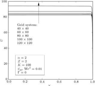
Figure 2. Grid dependency analysis of the velocity prole at the channel center.
4. Results and discussion
First of all, a mesh dependency analysis is performed to nd out the minimum number of grid points that provides suciently accurate results. A mesh depen-dency of the velocity prole is performed in Figure 2. This gure shows that no signicant change is occurred in the results by increasing the number of grid points in each direction from 100 to 120. More precisely, the dierence between the maximum velocity values obtained by these grid systems is only about 1%. The dependency of the Poiseuille number on the number of grid points is also given in Table 1. When the number of grid points in each direction from 100 is increased to 120, only about 0.2% change is occurred in the Poiseuille number. Hence, it seems that a 120 120 grid system can provide suciently accurate results, especially because only the graphical data is presented here.
To estimate the value of 2geWe2 for a typical
microuidic application, a channel height of 100 m is considered. Moreover, the parameter 2ge may be
considered to be at most of the order 0.1, based on 2ge,FENE-P= 1=(q + 5). Assuming an electroosmotic
velocity of 1 mms 1, the parameter 2
geWe2, then, will
have a maximum value of 0.1 for ge = 0:1 [38]. The
minimum value of 2geWe2 is clearly zero,
correspond-ing to a Newtonian behavior. Hence, the range 0-0.1 is considered for 2geWe2.
For validation of the numerical method, the re-sults are compared with existing literature data for
Table 1. Mesh dependency of the Poiseuille number values. Here, the ow parameters are the same as those of Figure 2. Number of
grid points 40 40 60 60 80 80 100 100 120 120
the limiting case of a parallel plate geometry. In this respect, the data reported by Afonso et al. [24] is chosen for comparison. A large aspect ratio of = 50 is considered here for the channel to imitate a slit, and the velocity prole across the channel height at the center of microchannel, that is x = 0, is chosen for a more reasonable comparison. Figure 3 shows the comparison between the velocity proles obtained in the present study with those given by Afonso et al. [24]. As seen, a complete agreement is observed between the results. It should be pointed out that the denitions of the Weissenberg number, We, and the velocity scale ratio, , in Ref. [24], are completely dierent from ours and
Figure 3. Comparison between the velocity proles obtained in the present study at the limiting case of a parallel plate channel and those of Afonso et al. [24].
Table 2. Comparison between the present results and the results of Vakili et al. [21].
K
fRe
Discrepancy (%) Present
study
Vakili et al. [21]
5 8.7237 8.7264 0.031
10 18.7234 18.7267 0.018 50 98.7139 98.7263 0.013 100 198.6985 198.7268 0.014
we have therefore recalculated their data based on the present denitions.
The present Poiseuille numbers are also compared with the results of Vakili et al. [21] in Table 2. This comparison is done assuming a Newtonian uid ow in a channel of square cross section. It can be seen that the results are in complete agreement; the maximum relative error is only about 0.03% which is quite reasonable.
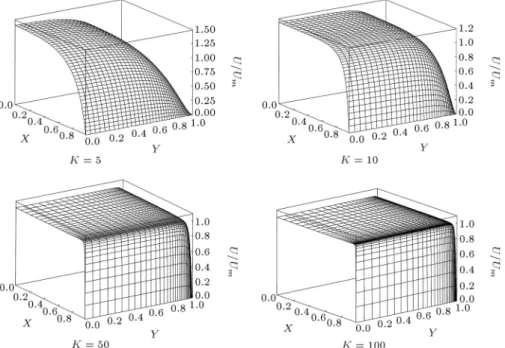
The presentation of the results is continued by giving the distribution of U=Um at dierent values of
K for 2geWe2= 0:1 in Figure 4. It can be seen that for
smaller values of K, such as K = 5, the velocity prole seems nearly parabolic and it becomes more plug-like as K increases. For K = 5, the EDL is relatively thick and the electric body force exists throughout the entire channel. Thus, the velocity variations exist in almost the whole channel domain, which results in a nearly parabolic prole. For higher values of K, such as K = 100, the EDL is conned to a thin layer near the wall. Therefore, the velocity variations exist only in this layer
Figure 4. Distribution of U=Umfor purely electroosmotic ow in a square duct with 2geWe2= 0:01 and Z = 2 at dierent values of K.
Figure 5. Dimensionless velocity at centerline for purely electroosmotic ow at dierent values of Z.
and the outside uid is dragged by the uid within EDL, creating a plug-like prole.
Figure 5 illustrates the proles of the dimension-less velocity at centerline for purely electroosmotic ow of a viscoelastic uid with 2geWe2 = 0:1 at dierent
zeta potentials. The predictions of the Debye-Huckel approximation, which are independent of Z, are also shown with symbols. As expected, an increase in zeta potential leads to an increase in the velocity, because of increasing the electroosmotic body force. Moreover, this gure reveals that the use of the Debye-Huckel linearization may lead to signicant errors in predict-ing the electroosmotic velocity of viscoelastic uids, as compared to the Newtonian uids for which this validation is valid for Z 2 [39]. However, Figure 6 shows that this linearization holds even at high zeta potentials, provided the velocity is normalized with the mean velocity. This means that, the Debye-Huckel linearization can approximately predict the shape of
Figure 6. Normalized velocity at centerline for purely electroosmotic ow at dierent values of Z.
Figure 7. Velocity prole at centerline for purely electroosmotic ow at dierent levels of elasticity.
the velocity prole even at high zeta potentials, even though it fails to obtain the correct velocity magnitude. The eect of elasticity, characterized by 2geWe2,
on the velocity prole, is observed in Figure 7. It is visible that elasticity eects drastically increase the uid velocity. For a better evaluation of the elasticity eects, the normalized velocity at centerline for purely electroosmotic ow at dierent values of 2geWe2 is
given in Figure 8. As seen, an increase in 2geWe2
gives rise to a more uniform velocity prole due to higher elasticity eects. In other words, uid tends to behave more like a solid with the same velocities for its composed particles.
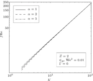
Figures 9 and 10 respectively depict the dimen-sionless mean velocity and Poiseuille number values versus K at dierent channel aspect ratios. It is observed that both of these parameters are increasing functions of K. The variations of fRe with K is expected because, as is clear from Figure 4, an increase
Figure 8. Normalized velocity at centerline for purely electroosmotic ow at dierent levels of elasticity.
Figure 9. Dimensionless mean velocity versus the dimensionless Debye-Huckel parameter.
Figure 10. Poiseuille number versus the dimensionless Debye-Huckel parameter.
in this parameter gives rise to higher velocity gradients at the wall. However, at rst glance, the variations of Um with K seem to be odd as we would expect
that the mean velocity would tend to an asymptotic value at high amounts of K. For interpretation of this odd behavior, let us assume that the Debye length remains unchanged while increasing K. Hence, for increasing K, the channel height should increase. Accordingly, for the Weissenberg number to remain unchanged, the relaxation time should increase. The increase in the relaxation time is to say that the level of elasticity is increased. As we saw, a higher level of elasticity is leading to higher velocities. Therefore, the velocity is an increasing function of K even at high values of this parameter. It is worth noting that by using the Debye length as the length scale in the denition of We the mean velocity will tend to an asymptotic value at high values of K [24]. It is also observed in Figure 9 that a higher channel aspect ratio results in a higher mean velocity. This is due
Figure 11. Umversus 2geWe2 at dierent values of and .
to the fact that, as the channel approaches a square shape, the corner eects become more prominent, leading to smaller amounts of the mean velocity. The aspect ratio dependency of the mean velocity vanishes at higher values of K due to the establishment of a nearly uniform velocity prole. The higher mean velocities for higher values of , as expected, lead to higher Poiseuille numbers, as observed in Fig-ure 10.
As the last illustration, the values of the dimen-sionless mean velocity are depicted versus 2ge We2 in
Figure 11. It can be seen that Um is almost a linear
increasing function of 2ge We2, regardless of and
. In addition, as expected, the mean velocity is an increasing function of the velocity scale ratio, because of increasing the pressure driving force. Another point taken from Figure 11 is that the pressure eects are more pronounced when the channel shape deviates from a rectangular geometry. As increases the distance between the two vertical walls is increased for a given channel height, resulting in smaller sur-face eects at the channel center. This, in turn, prepares the way for a higher eect of the pressure force.
It is worth mentioning that the linearity of Um 2ge We2 graph has an interesting outcome. It
means that the velocity gradient at the wall is almost a linear function of 2ge We2. Combining Eqs. (27)
and (28) with the consideration of the fact that usually ge>> 1, due to huge values of stress near the wall for
an electroosmotic ow, it can be concluded that both Txz and Tyz at the wall are independent of 2ge We2.
This, according to Eq. (34), leads to the disappearance of the dependency of the Poiseuille number on the level of elasticity in the uid. This conclusion is justied by our ndings. The pertinent graphs are not shown here in order to save space.
5. Conclusions
In this paper, the viscoelasticity eects on fully devel-oped electroosmotic ow in a rectangular microchan-nel were being investigated, utilizing both PTT and FENE-P constitutive equations. The problem was handled numerically, using a nite dierence based method for a non-uniform grid. Instead of two separate analyses, an analysis was performed for both models, considering generalized parameters. The obtained results were validated using available literature data. A comprehensive parametric study showed that al-though the validity range of the Debye-Huckel lin-earization may be much narrower for viscoelastic uids as compared to that of Newtonian uids, however, this approximation holds even at high zeta potentials, provided the velocity is normalized with the mean velocity. It was also observed that the mean velocity is almost a linear function of the level of elasticity in the uid. This linearity was found to lead to the disappearance of the dependency of the Poiseuille number on the level of elasticity in the uid. Moreover, the pressure eects are pronounced when the channel shape deviates from a square geometry. Last but not least, both the mean velocity and Poiseuille number are increasing functions of the channel aspect ratio.
References
1. Kirby, B.J., Micro- and Nanoscale Fluid Mechanics; Transport in Microuidic Devices, Cambridge Univer-sity Press, New York (2010).
2. Reuss, F.F. \Charge-induced ow", Proceedings of the Imperial Society of Naturalists of Moscow, 3, pp. 327-344 (1809).
3. Diez, F.J., Hernaiz, G., Miranda, J.J. and Sureda, M. \On the capabilities of nano electrokinetic thrusters for space propulsion", Acta Astronautica, 83, pp. 97-107 (2013).
4. Sadeghi, A., Kazemi, Y. and Saidi, M.H. \Joule heating eects in electrokinetically driven ow through rectangular microchannels: An analytical approach", Nanoscale and Microscale Thermophysical Engineer-ing, 17, pp. 173-193 (2013).
5. Burgreen, D. and Nakache, F.R. \Electrokinetic Flow in Ultrane Capillary Slits", Journal of Physical Chemistry, 68, pp. 1084-1091 (1964).
6. Rice, C.L. and Whitehead, R. \Electrokinetic ow in a narrow cylindrical capillary", Journal of Physical Chemistry, 69, pp. 4017-4024 (1965).
7. Levine, S., Marriott, J.R., Neale, G. and Epstein, N. \Theory of electrokinetic ow in ne cylindrical capillaries at high zeta-potentials", Journal of Colloid and Interface Science, 52, pp. 136-149 (1975).
8. Tsao, H.-K. \Electroosmotic ow through an annulus", Journal of Colloid and Interface Science, 225, pp. 247-250 (2000).
9. Kang, Y., Yang, C. and Huang, X. \Electroosmotic ow in a capillary annulus with high zeta potentials", Journal of Colloid and Interface Science, 253, pp. 285-294 (2002).
10. Yang, D. \Analytical solution of mixed electroosmotic and pressure-driven ow in rectangular microchan-nels", Key Engineering Materials, 483, pp. 679-683 (2011).
11. Wang, C.Y., Liu, Y.H. and Chang, C.C. \Analytical solution of electro-osmotic ow in a semicircular mi-crochannel", Physics of Fluids, 20, p. 063105 (2008).
12. Wang, C.Y. and Chang, C.C. \EOF using the Ritz method: Application to superelliptic microchannels", Electrophoresis, 28, pp. 3296-3301 (2007).
13. Goswami, P. and Chakraborty, S. \Semi-analytical so-lutions for electroosmotic ows with interfacial slip in microchannels of complex cross-sectional shapes", Mi-crouidics and Nanouidics, 11, pp. 255-267 (2011).
14. Vocale, P., Geri, M., Morini, G.L. and Spiga, M. \Electro-osmotic ows inside triangular microchan-nels", Journal of Physics: Conference Series, 501, 012026 (2014).
15. Das, S. and Chakraborty, S. \Analytical solutions for velocity, temperature and concentration distribution in electroosmotic microchannel ows of a non-Newtonian bio-uid", Analytica Chimica Acta, 559, pp. 15-24 (2006).
16. Zhao, C., Zholkovskij, E., Masliyah, J. and Yang, C. \Analysis of electroosmotic ow of power-law uids in a slit microchannel", Journal of Colloid and Interface Science, 326, pp. 503-510 (2008).
17. Zhao, C. and Yang, C. \Nonlinear Smoluchowski veloc-ity for electroosmosis of power-law uids over a surface with arbitrary zeta potentials", Electrophoresis, 31, pp. 973-979 (2010).
18. Vasu, N. and De, S. \Electroosmotic ow of power-law uids at high zeta potentials", Colloids and Surfaces A: Physicochemical and Engineering Aspects, 368, pp. 44-52 (2010).
19. Tang, G.H., Li, X.F., He, Y.L. and Tao, W.Q. \Elec-troosmotic ow of non-newtonian uid in microchan-nels", Journal of Non-Newtonian Fluid Mechanics, 157, pp. 133-137 (2009).
20. Tang, G.H., Ye, P.X. and Tao, W.Q. \Pressure-driven and electroosmotic non-newtonian ows through mi-croporous media via lattice Boltzmann method", Jour-nal of Non-Newtonian Fluid Mechanics, 165, pp. 1536-1542 (2010).
21. Vakili, M.A., Sadeghi, A., Saidi, M.H. and Mozafari, A.A. \Electrokinetically driven uidic transport of power-law uids in rectangular microchannels", Col-loids and Surfaces A: Physicochemical and Engineering Aspects, 414, pp. 440-456 (2012).
22. Park, H.M. and Lee, W.M. \Helmholtz-Smoluchowski velocity for viscoelastic electroosmotic ows", Journal of Colloid and Interface Science, 317, pp. 631-636 (2008).
23. Dhinakaran, S., Afonso, A.M., Alves, M.A. and Pinho, F.T. \Steady viscoelastic uid ow between parallel plates under electro-osmotic forces: Phan-Thien-Tanner model", Journal of Colloid and Interface Science, 344, pp. 513-520 (2010).
24. Afonso, A.M., Alves, M.A. and Pinho, F.T. \Analyt-ical solution of mixed electro-osmotic/pressure driven ows of viscoelastic uids in microchannels", Journal of Non-Newtonian Fluid Mechanics, 159, pp. 50-63 (2009).
25. Afonso, A.M., Pinho, F.T. and Alves, M.A. \Electro-osmosis of viscoelastic uids and prediction of electro-elastic ow instabilities in a cross slot using a nite-volume method", Journal of Non-Newtonian Fluid Mechanics, 179-180, pp. 55-68 (2012).
26. Afonso, A.M., Alves, M.A. and Pinho, F.T. \Ana-lytical solution of two-uid electro-osmotic ows of viscoelastic uids", Journal of Colloid and Interface Science, 395, pp. 277-286 (2013).
27. Sousa, J.J., Afonso, A.M., Pinho, F.T. and Alves, M.A. \Eect of the skimming layer on electro-osmotic-Poiseuille ows of viscoelastic uids", Microuidics and Nanouidics, 10, pp. 107-122 (2011).
28. Bandopadhyay, A. and Chakraborty, S. \Electroki-netically induced alterations in dynamic response of viscoelastic uids in narrow connements", Physical Review E - Statistical, Nonlinear and Soft Matter Physics, 85, p. 056302 (2012).
29. Bandopadhyay, A. and Chakraborty, S. \Giant aug-mentations in electro-hydro-dynamic energy conver-sion eciencies of nanouidic devices using viscoelastic uids", Applied Physics Letters, 101, p. 043905 (2012).
30. Bandopadhyay, A., Ghosh, U. and Chakraborty, S. \Time periodic electroosmosis of linear viscoelastic liquids over patterned charged surfaces in microuidic channels", Journal of Non-Newtonian Fluid Mechan-ics, 202, pp. 1-11 (2013).
31. Ferras, L.L., Afonso, A.M., Alves, M.A., Nobrega, J.M. and Pinho, F.T. \Analytical and numerical study of the electro-osmotic annular ow of viscoelastic uids", Journal of Colloid and Interface Science, 420, pp. 152-157 (2014).
32. Ghosal, S. \Lubrication theory for electro-osmotic ow in a microuidic channel of slowly varying cross-section and wall charge", Journal of Fluid Mechanics, 459, pp. 103-128 (2002).
33. Park, H.M., Lee, J.S. and Kim, T.W. \Comparison of the Nernst-Planck model and the Poisson-Boltzmann model for electroosmotic ows in microchannels", Journal of Colloid and Interface Science, 315, pp. 731-739 (2007).
34. Probstein, R.F., Physicochemical Hydrodynamics, Wi-ley, New York (1994).
35. Thien, N.P. and Tanner, R.I. \A new constitu-tive equation derived from network theory", Journal of Non-Newtonian Fluid Mechanics, 2, pp. 353-365 (1977).
36. Bird, R.B., Dotson, P.J. and Johnson, N.L. \Polymer solution rheology based on a nitely extensible bead-spring chain model", Journal of Non-Newtonian Fluid Mechanics, 7, pp. 213-235 (1980).
37. Anderson, A., Tannehill, J.C. and Pletcher, R.H., Computational Fluid Mechanics and Heat Transfer, Hemisphere, Washington (1984).
38. Thurston, G.B. \Rheological parameters for the viscos-ity, viscoelasticity and thixotropy of blood", Biorheol-ogy, 16, pp. 149-162 (1979).
39. Sadeghi, A., Yavari, H., Saidi, M.H. and Chakraborty, S. \Mixed electroosmotically and pressure-driven ow with temperature-dependent properties", Journal of Thermophysics and Heat Transfer, 25, pp. 432-442 (2011).
Biography
Mohammad Mahdy Heydari is a Professor of Mechanical Engineering at Malek Ashtar University of Technology, Tehran, Iran. He received his BSc at Khajeh Nasiredin University of Technology, Tehran, Iran, in 1994, his MSc at Tarbiat Modares University, Tehran, Iran, in 1996 and his PhD at Sharif University of Technology, Tehran, Iran, in 2007, all in Mechanical Engineering. His research interests involve propulsion, combustion, heat transfer and renewable energy.
![Figure 1. Schematic of the physical problem along with the coordinate system. EDLs are the regions between the dashed lines and the channel wall [21].](https://thumb-us.123doks.com/thumbv2/123dok_us/8384525.2227723/2.892.87.440.154.377/figure-schematic-physical-problem-coordinate-regions-dashed-channel.webp)