Sharif University of Technology
Scientia IranicaTransactions B: Mechanical Engineering www.scientiairanica.com
Research Note
Stabilization of a vibrating non-classical micro-cantilever
using electrostatic actuation
R. Vatankhah, F. Karami, H. Salarieh and A. Alasty
Department of Mechanical Engineering, Sharif University of Technology, Tehran, Iran. Received 1 October 2012; received in revised form 18 March 2013; accepted 14 May 2013KEYWORDS Vibration control; Non-classical micro-beam; Galerkin projection; Electrostatic actuation.
Abstract. A closed-loop control methodology is investigated for stabilization of a vibrating non-classical micro-scale Euler-Bernoulli beam with nonlinear electrostatic actuation. The dimensionless form of governing nonlinear Partial Dierential Equation (PDE) of the system is introduced. The Galerkin projection method is used to reduce the PDE of system to a set of nonlinear Ordinary Dierential Equations (ODE). In non-classical micro-beams, the constitutive equations are obtained based on the non-classical continuum mechanics. In this work, proper control laws are constructed to stabilize the free vibration of non-classical micro-beams whose governing PDE is derived based on the modied strain gradient theory as one of the most inclusive non-classical continuum theories. Numerical simulations are provided to illustrate the eectiveness and performance of the designed control scheme. Also, the results have been compared with those obtained by the classical model of micro-beam.
© 2013 Sharif University of Technology. All rights reserved.
1. Introduction
Many micro-cantilever beams based on MEMS instru-ments have drawn growing attention in modern tech-nology, such as vibration and shock sensors, Atomic Force Microscopes (AFM), micro-switches, mass sen-sors, and chemical sensors [1-3]. One of the most recurrent actuating and sensing methods in MEMS systems is based on electrostatic force because of its high eciency and simple structure and manufactur-ing. The combination of the electrostatic actuation and micro-beam structure has many applications in industrial and scientic elds like mass sensing systems, micro pressure sensors, micro exible joints, micro rate gyros and ink injection printers [4-6].
*. Corresponding author. Tel.: +98 21 66165504; Fax: +98 21 66000021
E-mail addresses: [email protected] (R. Vatankhah); [email protected] (F. Karami); [email protected] (H. Salarieh); [email protected] (A. Alasty)
Some papers were dedicated to derive the gov-erning equation of motion of electrostatically actuated beams, while some others considered the vibration analysis of them [7-9]. Pull-in instability has also drawn much attention in the literature. Several works were also dedicated to predict pull-in voltage and its properties [9-11].
Since mechanical vibration can be a main source of damage and restricts the performance and resolution of micro-scale instruments, the necessity for existence of a high performance control system has emerged in recent decades. Vibration control of a clamped-free micro-beam made of stainless steel was studied by Cunningham et al., and the rst two modes of vibration were actively suppressed [12]. In 1998, Wang considered a feedback control form to suppress mechanical vibration in a micro-cantilever beam by nonlinear electrostatic actuators via a switching con-troller [13]. Active vibration isolation of a stroke scanning probe microscope was accomplished by Yen et al. by using discrete sliding mode control to
treat eectively the unavoidable ground vibration [14]. Zhang et al. used the Rayleigh{Ritz method to reduce the order of the dynamical model of micro-cantilever beams and proposed a rational linearizing feedback controller with a high gain observer to eliminate the unwanted deection of the micro-cantilever beam sys-tem [15]. Many investigations considering feedback control problem of electrostatically actuated micro-systems have used lumped parameters assumption to simplify the governing PDEs of motion. Using this simplication, Vagia designed a switching PID control in 2008 [16]. In 2012, he suggested a sliding mode control to handle nonlinearity and uncertainty in the system parameters [17].
In various applications of MEMS-based micro-beams, the beam thickness is typically on the order of microns and sub-microns. In the recent decades, the size eect in micro-scale beams have been experimen-tally investigated in some metals and polymers such as those reported in [18-20]. These experiments signied that the classical strain-based mechanics theories can-not be used to describe the microstructure-dependent size eect. Hence, conventional continuum mechanics needs to be extended by using higher order continuum theories to interpret the size dependence phenomenon at small scale.
The eects of the strain gradients in linear elas-ticity were rstly investigated by Mindlin in 1964 [21]. As a common type of higher-order continuum theory, an improved version of the strain gradient theory was proposed by Fleck et al. in 1994 [18]. In 2003, a modied strain gradient elasticity theory as one of the most successful and inclusive higher-order continuum theories was elaborated by Lam et al. [22]. Recently, this theory has been broadly used to obtain the new governing equations and boundary conditions of micro-scale beams such as investigations illustrated in [23-25]. Also, a large number of publications and investigations in the eld of micro-scale beams have been devoted to study the static and dynamic behaviors of strain gradient micro-beams [26-29]. It can be seen from the literature that, although several investigations and analyses have been initiated to discuss the static and dynamic behavior and vibration analysis of non-classical strain gradient micro-beams in recent years, vibration control of non-classical micro-beams, such as strain gradient ones, has been excluded absolutely.
The present work intends to investigate the prob-lem of vibration suppression of a non-classical elec-trostatically actuated micro-cantilever using nonlinear control theory. For attaining this goal, rst, the dimensionless form of the governing nonlinear partial dierential equation of an electrostatically actuated Euler{Bernoulli micro-beam is determined based on the modied strain gradient theory introduced by
Lam et al. and then Galerkin projection method is employed to reduce the order of the system. The rst mode of the system is considered in the model of dynamics to design the controller and the rst four modes are chosen to apply the proposed controller and check the performance of the closed loop sys-tem.
2. Dynamic modeling
Based on the modied strain gradient theory pro-posed by Lam et al. [22], for a linear Euler-Bernoulli clamped-free micro-beam with uniform cross-section A and length L, the governing PDE of motion and corresponding boundary conditions are derived with the aid of Hamilton's principle as follows [23,30]:
K1@ 4w
@x4 K2
@6w
@x6 + A
@2w
@t2 = 0; (1)
8 > > > > > > > > > > > < > > > > > > > > > > > :
w (0; t) = @w(0;t) @x = @
2w(0;t)
@x2 = 0
K1@
3w(L;t)
@x3 K2@
5w(L;t)
@x5 = 0
K2@
4w(L;t)
@x4 K1@ 2w(L;t)
@x2 = 0
K2@
3w(L;t)
@x3 = 0
(2)
where x and t represent the independent spatial and time variables, respectively, indicates the beam density and w(x; t) denotes the lateral deection. Fur-thermore,
K1= EI + A
2l2
0+158 l21+ l22
;
K2= I
2l2
0+45l12
; (3)
where I is the area moment of inertia of the beam cross-section, E is the Young modulus and is the shear modulus. Moreover, l0, l1 and l2 appeared in
higher order stresses in the modied strain gradient theory [22], illustrate the additional independent ma-terial parameters.
Here, an electrostatically actuated non-classical strain gradient micro-beam formulation is attained using the Galerkin projection method. The beam is subjected to electrostatic force at its free end as stabilizing force. The electrostatic force is inherently unidirectional and one electrode is not able to exert force in both directions. So we need two opposite electrodes to produce both attracting and repelling forces. The suggested conguration is depicted in Figure 1.
Figure 1. An electrostatically actuated micro-beam.
It must be noticed that it is not mandatory to place electrodes at the tip of the beam; they could be placed in every location along the length of the can-tilever. The proper point for the location of electrodes can be obtained by controllability consideration which is beyond the scope of this study. For convenience, it is assumed that the electrodes are located at the tip.
The following equations show the magnitude of the electrostatic actuation force. When the electric potential is established between the electrode and the beam, a pulling force is founded and the beam is attracted toward the electrode.
Felec;l= 12"b (x)V 2 l (t)
(d w (x; t))2; or:
Felec;u= 12"b (x)V 2 u(t)
(d + w (x; t))2; (4) where d, b and " are initial distances between electrode and the beam, overlapping width of the beam and electrode and vacuum permittivity, respectively. is a spatial weighting function which is aimed to determine magnitude of the electrostatic force with respect to spatial independent variable. In the present work, a step function is used as a spatial weighting function in order to model the discontinuous geometry of electrodes. V is the applied voltage to the electrodes and w is the lateral displacement of the beam which is a function of temporal and spatial independent variables. \u" and \l" notations demonstrate the force that is generated due to upper and lower electrodes, respectively. To produce full control over the tip displacement of beams, each electrode has separate electrical circuit and dierent voltages are applied to each electrode. To avoid exerting opposite forces to the beam at once, each electrode is charged only if the other one is oine. It means that at each instant only one electrode is charged.
Using the modied strain gradient theory in well-known Euler-Bernoulli beam model, and the proposed electrostatic actuation terms, the following equation of motion is obtained.
K1@ 4w(x; t)
@x4 K2
@6w(x; t)
@x6 + bh
@2w(x; t)
@t2 =
1 2"b (x)V2
l (t)
(d w (x; t))2
(x)V2 u(t)
(d + w (x; t))2 !
: (5) The rst term in the right hand side of the equation represents the attracting force of the bottom electrode and the second term is corresponded to the upper elec-trode whose minus sign shows the opposite direction of the force [7].
In the above equation, h demonstrates the beam thickness. The dimensionless form of Eq. (5) can be obtained as below:
^ K1@
4w(^x; ^t)^
@^x4 K^2
@6w(^x; ^t)^
@^x6 +
@2w(^x; ^t)^
@^t2 =
(^x) ^V2 l (^t)
1 w(^x; ^t)^ 2
(^x) ^V2 u(^t)
1 + ^w(^x; ^t)2; (6) where:
^
K1= KEI1; K^2= EILK22; w =^ wd;
^x = Lx; ^t= tL2 s
EI
A; V =^ V q
2d3EI
"bL4
: (7)
The solution of Eq. (6) can be represented by a series of innite terms. Using the decomposition of temporal and spatial parts of the preceding equation solution, the lateral displacement of the beam can be written in the following form:
^
w(^x; ^t) =X1
i=1
ui(^t)i(^x); (8)
where ui is the temporal part of the ith mode of the
solution and i is the assumed mode shape of the ith
mode. The functions is must satisfy dimensionless
form of six boundary conditions of the beam given in Eq. (2) and are preferably orthogonal to decouple thoroughly the linear part of Eq. (6) for dierent modes. To apply classical methods of nonlinear control theory for designing a stabilizing control, the PDE of motion should convert into a set of ODEs in which every equation of this set corresponds to one mode of the system. The Galerkin projection method is used to convert Eq. (6) into a desired set of ODEs. To use the Galerkin method, the actuation terms must be expanded using Taylor series as follows:
^
Felec= ^V 2 l
(1 w)^ 2
^V2 u
^V2
l 1 + 2 ^w + 3 ^w2+ 4 ^w3+ :::
^V2
u 1 2 ^w + 3 ^w2 4 ^w3+ :::
=
^V2 l
1
X
i=1
i ^wi 1 ^V2 u
1
X
i=1
( 1)i+1i ^wi 1: (9)
Substituting Eq. (8) and the result of Eq. (9) into Eq. (6) and using the Galerkin method lead to the next equation:
Z 1
0 j
0 B B B B B @ ^ K1@ ^x@44
1
P
i=1uii
^ K2@ ^x@66
1
P
i=1uii
+@2
@^t2
1
P
i=1uii ^V 2 l
1
P
i=1i (uii)
i 1
+ ^V2 u
1
P
i=1( 1) i+1i (u
ii)
i 1 1 C C C C C A
d^x = 0: (10)
Orthogonality of the mode shapes brings about the decoupling of the linear parts of the equation of motion, but because of the nonlinear terms which correspond to actuation forces, the ODE of each mode contains some temporal terms of the other modes. Integrating Eq. (10) leads to the following ODE:
uj+ uj =
Z 1
0 j ^V 2 l
1
X
i=1
i (uii)
i 1
! d^x
Z 1
o j ^V 2 u
1
X
i=1
( 1)i+1i(u ii)i 1
! d^x;
(11) where is dened as:
= Z 1
0
^ K1j d
4
d^x4j K^2j
d6
d^x6j
d^x: (12)
3. Control system
The objective of this section is deriving a feedback con-trol law to stabilize undesired vibration of the micro-cantilever beam with taking into account the eect of strain gradient phenomenon. The design is based on the set of ODEs of motion which was derived in the previous section. The aim of the control system is to stabilize the advert vibrations of the micro-cantilever and restore it to its rest point. The rst mode of the strain gradient micro-cantilever is considered in the model for controller design. This mode dominates the dynamic response of the beam, and stabilization of this mode would stabilize signicantly the entire vibration of the beam. On the other hand, including the higher modes imposes need of more electrodes to actuate the beam. The actuation force is approximated by its rst four terms of Taylor expansion. This approximation
is used only for controller model, but in the plant model the right hand side of Eq. (11) is integrated directly over spatial domain, without approximation by Taylor expansion. It can be interpreted that the whole terms of the Taylor series are considered in the plant model. This method signicantly improved accuracy of the numerical solution in the expense of increasing calculations. Simulations show that approximation by four terms has enough accuracy and increasing the terms would not improve the response of the system. The equation of motion for the rst mode is depicted as follows:
u1+ u1=
Z 1
0 1
^ V2
l
1 + 2u11+ 3u2121+ 4u3131
d^x: (13) The controller will convert the characteristic equation of the closed loop system into the following form:
u1+ c1_u1+ c2u1= 0; (14)
where c1 and c2 are positive coecients that must be
chosen in a way to ensure the stability of the system. To do so, a feedback linearization method is used to eliminate the nonlinear part of the equation and form Eq. (14). Doing some math the actuating voltage is obtained in the form of:
^ V2
l =a c1_u1 c2u1+ u1
1+ a2u1+ a3u21+ a4u31; (15)
where ais are coecients which are obtained by
inte-grating the left part of Eq. (13) with respect to ^x. They are dened as follows:
a1=
Z 1
0 1d^x; a2=
Z 1
0 2 2 1d^x;
a3=
Z 1
0 3 3
1d^x; a4=
Z 1
0 4 4
1d^x: (16)
Substituting Eq. (15) in Eq. (13) would convert Eq. (13) into Eq. (14). The controller can be tuned by choosing proper c1 and c2 coecients. To generate
force in the opposite side (upward force) one must use the upper electrode as well. From Eq. (15), it is obvious that the left side of the equation must be positive to have physical meaning; this arises from unidirectional nature of the electrostatic actuation. When the left side term becomes negative, it means that upward force is needed. The upper electrode can generate this upward force by applying a voltage that is specied by using the below model:
u1+ u1=
Z 1
0 ^V 2 u
1 2u11+ 3u2121 4u3131
To convert the above equation into asymptotic stable form of Eq. (14), the following voltage is derived:
^ V2
u = a c1_u1 c2u1+ u1
1 a2u1+ a3u21 a4u31; (18)
where ais are dened in Eq. (16). A supervisory control
would decide which control voltage is valid based on the sign of the left parts of Eqs. (15) and (18). The positive sign is the criterion of applying the voltage to electrode.
4. Simulation results
In the previous section, a controller was designed to stabilize the vibration of a strain gradient micro-cantilever. In this part of the present work, numerical simulations are used to validate the proposed feedback control system. The parameters of the micro-cantilever which is modeled as plant of the system are shown in Table 1. To investigate the eect of unmodeled dy-namics on controller performance, the plant is modeled by rst four modes of the beam. So, the robustness of the proposed system will be tested by assuming higher modes and unmodeled fast dynamics of the system in simulations. In this research, it is assumed that all necessary states of the system are available via a proper estimation system, but the observation system is not included in present simulations. In future investigation, the authors will consider a state estimation system by designing a proper nonlinear observer. The observabillity of similar nonlinear system was proved in pervious works [31-32].
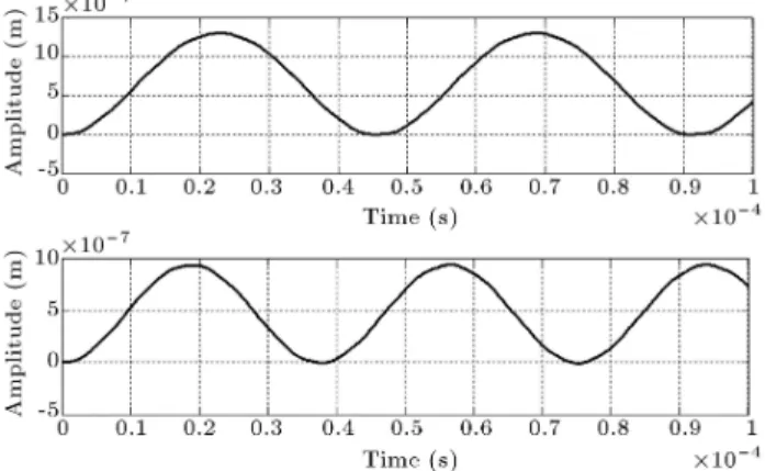
In the rst simulation, the vibration of the beam due to a constant voltage is investigated. The input voltage is applied as a step function. The simulation is carried out for both classical and strain gradient Euler-Bernoulli micro-beam models. Figure 2 shows the result of the simulation in this case.
Comparison between the simulation results of these two models shows signicant dierences in the frequency and amplitude of the time response. The time response of the tip displacement of classical Euler-Bernoulli beam model to the step input exhibits lower frequency which is in contrast to fast response of the strain gradient model. Also, the tip displacement amplitude of the classical model is higher than that of the second one. This matter can be explained by considering the dierence between stiness of the two models. Taking the eect of strain gradient into
Figure 2. Tip displacement response of the beam to a step input voltage for classical (upper) and non-classical (lower) beam models. The thickness of the micro-beam is 17 m.
Figure 3. Tip displacement response of the beam to a step input voltage for classical (upper) and non-classical (lower) beam models. The thickness of the beam is 80 m.
account increases the stiness of the beam. Much thinner the beam is, this added stiness is larger. In Figure 3, the result of the same simulation is carried out but the thickness of the beam is taken to be about 5 times greater than the rst simulation. It is obvious that the dierence in response of the two models is far less than the rst simulation in which the thickness of the beam was lesser. But the dierence in amplitude of the response is again considerable. In the second simulation, the performance of the proposed stabilizing control system is studied. An initial displacement is applied at the tip of the beam and the controller would stabilize the resulted vibration. In the simulation, the parameters of Table 1 are used.
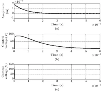
In Figure 4, the result of the simulation for the
Table 1. Parameters of the non-classical micro-cantilever [33]. Length Modulus of
elasticity Width Thickness Density l0 l1 l2
Initial gap 340 m 1.44 GPa 34 m 17 m 1000 kg/m3 17.6 m 17.6 m 17.6 m 3 m
Figure 4. (a) Tip displacement of the beam, (b) lower electrode control voltage, and (c) upper electrode control voltage of the stabilized micro-cantilever with
non-classical beam model.
Figure 5. (a) Tip displacement of the beam, (b) lower electrode control voltage, and (c) upper electrode control voltage of the stabilized micro-cantilever with classical beam model.
beam with stabilizing feedback control laws is depicted. The result shows smooth stabilizing of the beam. In the next simulation, the eect of neglecting strain gradient term in the model, which is used to design the controller, is studied. Classical theory of the Euler-Bernoulli beam is used for controller design, but the plant is simulated as a strain gradient included beam. In Figure 5, the result of simulation is illustrated.
The result demonstrates that the response of the
Figure 6. (a) Tip displacement, (b) lower electrode control voltage, and (c) upper electrode control voltage of the stabilized micro-cantilever with linear PID controller.
beam exhibits increasing in the controller signal which is signicantly higher than the case where the strain gradient is included in the controller model. The mismatch between the actual plant and the controller model leads to the poor controller performance. The maximum control eort in the latter case is about two times greater than the rst case. In addition, the higher order dynamics eects which are neglected in the controller model can be observed in the form of small oscillations in the time response of the system.
The last simulation is dedicated for a comparison between the proposed nonlinear control scheme and a linear controller. A PID controller is used and its performance is indicated in Figure 6. As shown in this gure, the linear controller can stabilize the vibration of the beam using very large control eort in comparison to the proposed nonlinear controller. Also, the eect of the higher order dynamics in the system response is stronger than the case of using nonlinear controller.
5. Conclusion
In this research, the problem of vibration suppression of a clamped-free strain gradient Euler-Bernoulli micro-beam is studied. The nonlinear electrostatic actu-ation is considered to achieve the control objective. Nonlinear PDE of the motion of a strain gradient micro-beam with electrostatic actuation is obtained in dimensionless form. State space representation of the system is instituted by employing the Galerkin method. Then, for the obtained ODE model, a feed-back control law is designed to stabilize the undesired vibration of the micro-cantilever beam with taking into account the eect of strain gradient phenomenon.
Finally, computer simulation is implemented to observe the eectiveness of the proposed control technique. Numerical results obtained by considering the non-classical model are compared with those obtained by the classical one. Numerical simulations show signif-icant dierences between the results of non-classical and classical models. These dierences decrease and diminish by increasing the micro-beam thickness. In this work, the eect of observer errors in estimating the needed states for the controller is ignored, and it is assumed that the whole states are available for feedback. In the future work, this important factor will be studied and considered in the system perfor-mance.
References
1. de Boer, M.P., Luck, D.L., Ashurst, W.R., Maboudian, R., Corwin, A.D., Walraven, J.A. and Redmond, J.M. \High-performance surface-micromachined inchworm actuator", J. Microelectromech. Syst., 13(1), pp. 63-74 (2004).
2. Lun, F.Y., Zhang, P., Gao, F.B. and Jia, H.G. \Design and fabrication of micro-optomechanical vibration sen-sor", Microfab. Technol., 120(1), pp. 61-64 (2006).
3. Batra, R.C., Porri, M. and Spinello, D. \Vibrations of narrow microbeams predeformed by an electric eld", J. Sound Vib., 309(3-5), pp. 600-612 (2008).
4. Ekinci, K.L., Yang, Y.T. and Roukes, M.L. \Ultimate limits to inertial mass sensing based upon nanoelec-tromechanical systems", J. Appl. Phys., 95, pp. 2682-2687 (2004).
5. Yasuda, T., Shimoyama, I. and Miura, H. \Electro-statically driven micro elastic joints", IEEE Computer Society, International Conference on Intelligent Robots and Systems, pp. 242-245 (1995).
6. Chu, L.L., Que, L. and Gianchandani, Y.B. \Measure-ments of material properties using dierential capaci-tive strain sensors", J. Microelectromech. Syst., 11(5), pp. 489-498 (2002).
7. Abdel-Rahman, E.M., Younis, M.I. and Nayfeh, A.H. \Characterization of the mechanical behavior of an electrically actuated microbeam", J. Micromech. Mi-croeng., 12, pp. 759-765 (2002).
8. Brusa, E., De Bona, F., Gugliotta, A. and Soma, A. \Modeling and prediction of the dynamic behaviour of microbeams under electrostatic load", Analog. Integr. Circ. S., 40(2), pp. 155-164 (2004).
9. Mojahedi, M., Moghimi Zand, M. and Ahmadian, M.T. \Static pull-in analysis of electrostatically ac-tuated microbeams using homotopy perturbation method", Appl. Math. Model., 34(4), pp. 1032-1041 (2011).
10. Rezazadeh, G., Tahmasebi, A. and Ziaei-rad, S. \Non-linear electrostatic behavior for two elastic parallel xed-xed and cantilever microbeams", Mechatronics., 19(6), pp. 840-846 (2009).
11. Lakrad, F. and Belhaq, M. \Suppression of pull-in in-stability in MEMS using a high-frequency actuation", Commun. Nonlinear Sci. Numer. Simul., 15(11), pp. 3640-3646 (2010).
12. Cunningham, M.J., Jenkins, D.F.L., Clegg, W.W. and Bakush, M.M. \Active vibration control and actuation of a small cantilever for applications in scanning probe instruments", Sens. Actuators. A., 50(1), pp. 147-150 (1995).
13. Wang, P.K.C. \Feedback control of vibrations in a micromachined cantilever beam with electrostatic ac-tuators", J. Sound Vib., 213(3), pp. 537-550 (1998).
14. Yen, J.Y., Lan, K.J. and Kramar, J.A. \Active vibration isolation of a large stroke scanning probe microscope by using discrete sliding mode control", Sens. Actuators. A., 121(1), pp. 243-250 (2005).
15. Zhang, W., Meng, G. and Li, H. \Adaptive vibration control of micro-cantilever beam with piezoelectric actuator in MEMS", Int. J. Adv. Manuf. Technol., 28(3), pp. 321-327 (2006).
16. Vagia, M., Nikolakopoulos, G. and Tzes, A. \Design of a robust PID-control switching scheme for an elec-trostatic micro-actuator", Control Eng. Pract., 16(11), pp. 1321-1328 (2008).
17. Vagia, M. \A frequency independent approximation and a sliding mode control scheme for a system of a micro-cantilever beam", ISA. Trans., 51(2), pp. 325-332 (2012).
18. Fleck, N.A., Muller, G.M., Ashby, M.F. and Hutchin-son, J.W. \Strain gradient plasticity: Theory and experiment", Acta. Metall. Mater., 42(2), pp. 475-487 (1994).
19. Ma, Q. and Clarke, D.R. \Size dependent hardness of silver single crystals", J. Mater. Res., 10(04), pp. 853-863 (1995).
20. Stolken, J.S. and Evans, A.G. \A microbend test method for measuring the plasticity length scale", Acta Mater., 46(14), pp. 5109-5115 (1998).
21. Mindlin, R.D. \Micro-structure in linear elasticity", Archs Ration. Mech. Analysis, 16, pp. 51-78 (1964).
22. Lam, D.C.C., Yang, F., Chong, A.C.M., Wang, J. and Tong, P. \Experiments and theory in strain gradient elasticity", J. Mech. Phys. Solids., 51(8), pp. 1477-1508 (2003).
23. Kong, S., Zhou, S., Nie, Z. and Wang, K. \Static and dynamic analysis of micro beams based on strain gradient elasticity theory", Int. J. Eng. Sci., 47(4), pp. 487-498 (2009).
24. Ma, H.M., Gao, X.L. and Reddy, J.N. \A microstructure-dependent Timoshenko beam model based on a modied couple stress theory", J. Mech. Phys. Solids, 56(12), pp. 3379-3391 (2008).
25. Xia, W., Wang, L. and Yin, L. \Nonlinear non-classical microscale beams: Static bending, postbuckling and free vibration", Int. J. Eng. Sci., 48(12), pp. 2044-2053 (2010).
26. Vatankhah, R., Kahrobaiyan, M.H., Alasty, A. and Ahmadian, M.T. \Nonlinear forced vibration of strain gradient microbeams", Appl. Math. Model., 37, pp. 8363-8382 (2013).
27. Kahrobaiyan, M.H., Asghari, M., Rahaeifard, M. and Ahmadian, M.T. \Investigation of the size-dependent dynamic characteristics of atomic force microscope microcantilevers based on the modied couple stress theory", Int. J. Eng. Sci., 48(12), pp. 1985-1994 (2010).
28. Zhao, J., Zhou, S., Wang, B. and Wang, X. \Nonlinear microbeam model based on strain gradient theory", Appl. Math. Modell., 36, pp. 2674-2686 (2012).
29. Ansari, R., Gholami, R. and Sahmani, S. \Free vi-bration analysis of size-dependent functionally graded microbeams based on the strain gradient Timoshenko beam theory", Compos. Struct., 94(1), pp. 221-228 (2011).
30. Akgoz, B. and Civarlek, O. \Comment on \Static and dynamic analysis of micro beams based on strain gradient elasticity theory" by S. Kong, S. Zhou, Z. Nie, and K. Wang, (International Journal of Engineering Science, 47, 487-498, 2009)", Int. J. Eng. Sci., 55, pp. 279-281 (2012).
31. Shirazi, M.J., Salarieh, H., Alasty, A. and Shabani, R. \Tip tracking control of a micro-cantilever Timoshenko beam via piezoelectric actuator", J. Vib. Control., Article in Press, D.O.I.: 10.1177/1077546312447837.
32. Karami, F. and Salarieh, H. \Positioning control in micro-beams via electrostatic actuators and incom-plete state feedback", MSc Thesis, Department of Me-chanical Engineering, Sharif University of Technology, Tehran, Iran (2012).
33. Vatankhah, R., Naja, A., Salarieh, H. and Alasty, A. \Boundary stabilization of non-classical micro-scale beams", Appl. Math. Model., 37, pp. 8709-8724 (2013).
Biographies
Ramin Vatankhah received his BS degree in Me-chanical Engineering from Shiraz University, Shiraz,
Iran, in 2007, and his MS and PhD degrees in Me-chanical Engineering from Sharif University of Tech-nology, Tehran, Iran, in 2009 and 2013, respectively. His research interests include cooperative control of multiple autonomous agents, evolutionary computa-tion techniques and their applicacomputa-tions in mechanical engineering, boundary control of partial dierential equations and nonlinear control.
Farzad Karami received his BSc and MSc degrees in Mechanical Engineering from Sharif University of Technology, Tehran, Iran in 1987 and 1989. He is currently a PhD student in Khajeh Nasir Toosi University of Technology. His research interests include nonlinear dynamics and control and estimation theory. Hassan Salarieh received his BSc degree in Mechani-cal Engineering and also Pure Mathematics from Sharif University of Technology, Tehran, Iran in 2002. He graduated from the same university with MSc and PhD degrees in Mechanical Engineering in 2004 and 2008. At present, he is an associate professor in Mechanical Engineering at Sharif University of Technology. His elds of research are dynamical systems, control theory and stochastic systems.
Aria Alasty received his BSc and MSc degrees in Mechanical Engineering from Sharif University of Tech-nology, Tehran, Iran in 1987 and 1989. He also received his PhD degree in Mechanical Engineering from Carleton University, Ottawa, Canada, in 1996. At present, he is a professor of Mechanical Engineering at Sharif University of Technology. He has been a member of Center of Excellence in Design, Robotics, and Automation (CEDRA) since 2001. His elds of research are mainly in nonlinear and chaotic systems control, computational nano/micro mechanics and con-trol, special purpose robotics, robotic swarm concon-trol, and fuzzy system control.