User
Manual
Classic 1785 PLC5
Programmable
Controllers
(1785LT, LT2, LT3, LT4)
The illustrations, charts, sample programs, and layout examples shown in this guide are intended solely for purposes of example. Since there are many variables and requirements associated with any particular installation, Allen-Bradley does not assume responsibility or liability (to include intellectual property liability) for actual use based on the examples shown in this publication.
Allen-Bradley publication SGI-1.1, Safety Guidelines for the Application, Installation, and Maintenance of Solid State Control (available from your local Allen-Bradley office), describes some important differences between solid-state equipment and electromechanical devices that should be taken into consideration when applying products such as those described in this publication.
Reproduction of the contents of this copyrighted publication, in whole or in part, without written permission of Allen-Bradley Company, Inc., is prohibited.
Throughout this manual we use notes to make you aware of safety considerations:
ATTENTION: Identifies information about practices or
circumstances that can lead to personal injury or death, property damage, or economic loss.
Attention statements help you to: identify a hazard
avoid the hazard
recognize the consequences
Important: Identifies information that is critical for successful application
Summary of Changes
This manual has been revised to cover only Classic PLC-5 programmable controllers: PLC-5/10, -5/12, -5/15, and -5/25.
It has also been revised to include the accompanying design worksheets that were formerly available as a separate publication: 1785-5.2. This separate publication is no longer available; see Appendix B for these worksheets.
For information about Enhanced and Ethernet PLC-5 processors, see the Enhanced and Ethernet PLC-5 Programmable Controllers User Manual, publication 1785-6.5.12.
Summary of Changes
. . .
i
Classic PLC5 Programmable Controllers
. . .
iii
Purpose of this Manual . . . iii
Manual Organization . . . iv
How to Use this Manual . . . iv
Understanding Your System
. . .
11
Using this Chapter . . . 11
Understanding the Terms Used in this Chapter. . . 11
Designing Systems . . . 12
Preparing Your Functional Specification . . . 13
Introducing Classic PLC5 Processor Modules . . . 15
Using the Classic PLC5 Processor as a Remote I/O Scanner . . . . 18
Using the Classic PLC5 Processor as a Remote I/O Adapter . . . . 19
Choosing Hardware
. . .
21
Chapter Objectives. . . 21
Selecting I/O Modules. . . 21
Selecting I/O Adapter Modules . . . 24
Selecting I/O Chassis . . . 26
Selecting an Operator Interface . . . 26
Choosing a Classic PLC5 Processor for Your Application . . . 29
Selecting Power Supplies . . . 29
Selecting Memory Modules . . . 213
Selecting a Replacement Battery . . . 213
Selecting Complementary I/O . . . 213
Selecting a PLC5 Processor Backup System . . . 214
Selecting Link Terminators . . . 215
Connecting a Programming Terminal to a Processor Module . . . 215
Choosing Cables . . . 215
Placing System Hardware
. . .
31
Chapter Objectives. . . 31
Determining the Proper Environment . . . 31
Protecting Your Processor . . . 34
Avoiding Electrostatic Damage . . . 34
Laying Out Your Cable Raceway . . . 34
Planning Cabling . . . 35
Placing I/O Modules in Chassis . . . 41
Understanding the Terms Used in this Chapter . . . 42
Choosing the Addressing Mode. . . 43
Assigning Racks . . . 49
Addressing Complementary I/O . . . 412
Choosing Communication
. . .
51
Chapter Objectives. . . 51
Identifying Classic PLC5 Processor Channels/Connectors . . . 51
Configuring Communication for Your Processor . . . 53
Configuring a DH+ Link. . . 53
Connecting a DH+ Link to Data Highway . . . 510
Choosing Programming Terminal Connection . . . 510
Planning Your System Programs
. . .
61
Chapter Objectives. . . 61
Planning Application Programs . . . 61
Using SFCs with PLC5 Processors. . . 61
Preparing the Programs for Your Application . . . 63
Addressing Data Table Files . . . 67
Using the Processor Status File. . . 69
Selecting Interrupt Routines
. . .
71
Chapter Objectives. . . 71
Using Programming Features . . . 71
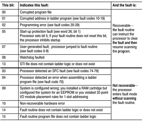
Writing a Fault Routine . . . 73
Understanding ProcessorDetected Major Faults . . . 711
Transferring Discrete and BlockTransfer Data
. . .
81
Chapter Objectives. . . 81
Transferring Data Using Adapter Mode . . . 81
Programming Discrete Transfer in Adapter Mode . . . 84
Programming Block Transfer in Adapter Mode . . . 87
Transferring Data Using Scanner Mode . . . 816
Programming Discrete Transfer in Scanner Mode . . . 816
Programming Block Transfer in Scanner Mode . . . 817
I/O Scanning Discrete and Block Transfer . . . 95
Instruction Timing and Memory Requirements . . . 97
Program Constants . . . 913
Direct and Indirect Elements . . . 913
Maximizing System Performance
. . .
101
Chapter Objectives. . . 101
Components of Throughput. . . 101
Input and Output Modules Delay . . . 101
I/O Backplane Transfer . . . 102
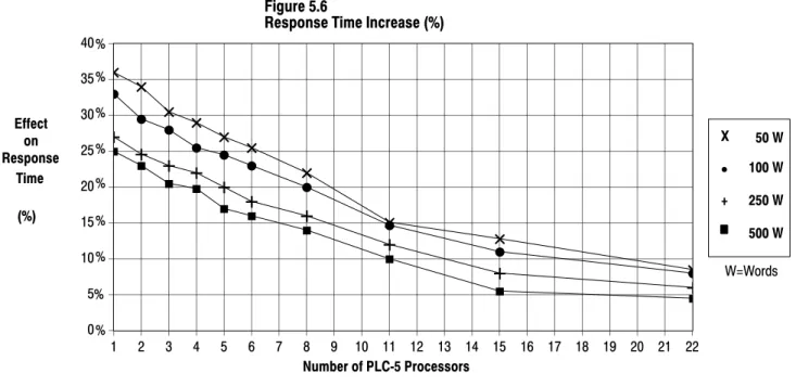
Remote I/O Scan Time . . . 102
Processor Time . . . 106
Calculating Throughput. . . 106
Selecting Switch Settings
. . .
A1
Chassis Backplane with Classic PLC5 Processor. . . A1
Chassis Backplane with Adapter Module . . . A2
Chassis Configuration Plug for Power Supply . . . A3
Remote I/O Adapter Module 1771ASB Series C without
Complementary I/O. . . A4
Remote I/O Adapter Module 1771ASB Series C with
Complementary I/O. . . A6
SW1 . . . A7
AdapterMode Processors SW2 in a PLC5 or Scanner Module. . A8
AdapterMode Processors SW2 in a PLC2/20, 2/30,
or Sub I/O Scanner Module System . . . A9
AdapterMode Processors SW2 in a PLC3 or PLC5/250
System with 8Word Groups . . . A10
AdapterMode Processors SW2 in a PLC3 or PLC5/250
System with 4Word Groups . . . A11
SW3 . . . A12
Design Worksheets
. . .
B1
Conventions Used in These Worksheets . . . B1
Prepare a Functional Specification. . . B2
Determine Control Strategy . . . B4
Identify Chassis Locations . . . B6
Select Module Types and List I/O Points. . . B7
Total I/O Module Requirements . . . B9
Assign I/O Modules to Chassis and Assign Addresses. . . B10
Select Power Supplies . . . B23
Choose a Programming Terminal. . . B24
Select Programming Terminal Configuration . . . B25
Select Operator Interface . . . B26
Classic PLC5 Programmable Controllers
Your Classic PLC-5 Programmable Controllers documentation is organized into manuals according to the tasks you perform. This organization lets you easily find the information you want without reading through information that is not related to your current task. The arrow in Figure 1 points to the book you are currently using.
Figure 1
Classic PLC5 Programmable Controllers Documentation Library
6200 or AI Series Software
Reference Instruction Set Instruction execution,
parameters, status bits and examples
1785 PLC5 Programmable Controllers
Quick Reference Quick access to switches,
status bits, indicators, instructions, SW screens 17857.1 17856.6.1 Classic 1785 PLC5 Programmable Controllers Hardware Installation How to install and set
switches for chassis, PLC5 processor, how
to wire and ground your system 17856.1 Classic 1785 PLC5 Programmable Controllers User Manual 17856.2.1 Explanation of processor functionality, system design, and programming considerations and worksheets
For more information on 1785 PLC-5 programmable controllers or the above publications, contact your local Allen-Bradley sales office, distributor, or system integrator.
This manual is intended to help you design a Classic PLC-5 programmable controller system. Use this manual to assist you in:
selecting the proper hardware components for your system
determining the important features of classic PLC-5 processors and how to use those features
How to Use
Your Documentation
This manual has ten chapters and two appendices. The following table lists each chapter or appendix with its corresponding title and a brief overview of the topics covered in it.
Chapter /
Appendix Title Topics Covered
1 Understanding Your System Provides an overview of Classic PLC5 processors in different system configurations. Provides an introduction to Classic PLC5 processors and their primary features and configurations. Also provides information on using a Classic PLC5 processor as a remote I/O scanner or a remote I/O adapter.
2 Choosing Hardware Provides information on your hardware choices when you design a Classic PLC5 processor system.
3 Placing System Hardware Describes proper environment, Classic PLC5 processor protection, and prevention of electrostatic damage for your Classic PLC5 programmable controller system. Also covers raceway and cable layout, backpanel spacing, and grounding configurations.
4 Assigning Addressing Mode,
Rack, and Groups Describes the I/O addressing modes that you can choose for your chassis. Explains how youassign group and rack numbers to your I/O chassis. Also covers how you configure complementary I/O by assigning rack and group addresses.
5 Choosing Communication Identifies each Classic 5 processor channel/connector, and explains how to configure your Classic PLC5 processor. Provides additional information about the Data Highway Plust
(DH+t) link, programming software, and programmingterminal connections.
6 Planning Your System Programs Explains the use of sequential function charts (SFCs). Provides guidelines and examples for preparing system programs. Provides a map of data table files and methods to address the data table files. Explains how to use the processor status file.
7 Selecting Interrupt Routines Summarizes the conditions for which you would choose fault routines for your application. Provides a definition of fault routines.
8 Transferring Discrete and
BlockTransfer Data Explains how your CLassic PLC5 processor transfers discrete and blocktransfer data in bothscanner and adapter modes. 9 Calculating Program Timing Provides an overview of processor scan timing. Lists execution times and memory
requirements for bit and word instructions as well as file instructions.
10 Maximizing System Performance Explains how to calculate throughput, and provides methods for optimizing I/O scan time. A Selecting Switch Settings Describes the switch settings for configuring a Classic PLC5 programmable controller system. B Design Worksheets Provides worksheets to help the designer plan the system and the installer to install the system.
The following flow chart demonstrates a thought process that you can use when you plan your Classic PLC-5 programmable controller system.
Manual Organization
System Design Determined Select I/O
modules, terminals Place hardware
Select I/O chassis Select power supply Select PLC5 processor
Select batteries and memory modules Complementary I/O selected? Backup system selected? Configure processor communication Configure Data Highway Plus Select programming software
Data table layout and processor status
Use fault routines Choosing Hardware and Placing System Hardware Choosing Communication Assigning Addressing Mode, Racks, and Groups
I/O update and ladder program scan times
Planning Your System Programs Calculating Program Timing and Maximizing System Performance Transfer data in adapter
and scanner modes
Transferring Discrete and Block Data Design SFCs
Select adapter modules
Assign addressing
Since your decisions cannot always be made as a part of a strictly linear process, you can choose to complete tasks in parallel. When you select your I/O modules, for example, you can also begin to lay out and address your modules. Consult chapter 3, “Placing System Hardware,” to determine environmental requirements, enclosures needed, cable layout, and grounding requirements for your chassis and I/O links. Also, you can choose to assess block-transfer timing when you determine where you will place your block-transfer modules (in the processor-resident local I/O chassis, extended-local I/O chassis, or remote I/O chassis).
Understanding Your System
If you want to read about: Go to page:
Terms used in this chapter 11
Designing systems 12
Preparing your functional specification 13
Identifying Classic PLC5 processor features 15
Using the Classic PLC5 processor as a remote I/O scanner 18
Using the Classic PLC5 processor as a remote I/O adapter 19
Become familiar with the following terms and their definitions.
Term Definition
Processorresident
local I/O chassis the I/O chassis in which the PLC5 processor is installed Processorresident
local I/O I/O modules located in the same chassis as the PLC5 processor Remote I/O link a serial communication link between a PLC5 processor port in scanner
mode and an adapter as well as I/O modules that are located remotely from the PLC5 processor
Remote I/O chassis the hardware enclosure that contains an adapter and I/O modules that are located remotely on a serial communication link to a PLC5 processor in scanner mode
Discretetransfer data data (words) transferred to/from a discrete I/O module
Blocktransfer data data transferred, in blocks of data up to 64 words, to/from a block transfer I/O module (for example, an analog module)
Using this Chapter
Understanding the Terms
Used in this Chapter
You can use Classic PLC-5 processors in a system that is designed for centralized control or in a system that is designed for distributed control.
Classic PLC5 Processor 1771ASB Remote I/O Adapter 1771ASB Remote I/O Adapter
Remote I/O Link
Programming Terminal
Chassis with Chassis with
Centralized control is a hierarchical system where control over an entire process is concentrated in one processor.
HP 9000 or VAX Host Programming Terminal with ControlView Software DH+ Link Pyramid Integrator
Remote I/O Link PanelView Operator Terminal Series 8600 CNC with Remote I/O SLC 5/01 Processor
7slot Modular System with 1747DCM Module DH+ Link
Distributed control is a system in which control and management functions are spread throughout a plant. Multiple processors handle the control and management functions and use a Data Highway or a bus system for communication. 6200 VMS INTERCHANGE Software Programming Terminal ControlView INTERCHANGE Software To DECnet r 18084
Consider the following items as general guidelines when designing your system.
Will your processor(s) be used in a centralized or distributed system? What type of process(es) will be controlled by the PLC-5 system? What processes will be controlled together?
What are the environmental and safety concerns?
Designing Systems
Determine the general criteria for your system. Use the chapters that follow to guide you through the criteria and choices for selecting the major Classic PLC-5 programmable controller system elements, as shown in Figure 1.1.
Figure 1.1
PLC5 Processor System Design Flow
System Design Determined Select I/O
modules, terminals Place hardware
Select I/O chassis Select power supply Select Classic PLC5 processor
Select batteries and memory modules Complementary I/O selected? Backup system selected? Configure processor communication Configure Data Highway Plus Select programming software
Data table layout and processor status
Use fault routines Choosing Hardware and Placing System Hardware Choosing Communication Assigning Addressing Mode, Racks, and Groups
I/O update and ladder program scan times
Planning Your System Programs Calculating Program Timing and Maximizing System Performance Transfer data in adapter
and scanner modes
Transferring Discrete and Block Data Design SFCs
Select adapter modules
Assign addressing
We recommend that you first develop a specification that defines your hardware selection and your programming application. The specification is a conceptual view of your system. Use it to determine your:
control strategy
hardware selection, layout, and addressing sequential function chart (SFC)
special programming features ladder-logic requirements
Preparing Your
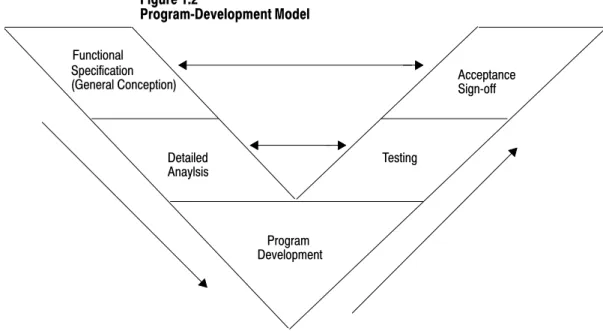
Figure 1.2 illustrates a program-development model that you can use. Figure 1.2 ProgramDevelopment Model Functional Specification Detailed Anaylsis (General Conception) Program Testing Acceptance Development Signoff
This model allows for the interaction of activities at the different levels. Each section represents an activity that you perform. Prepare a functional specification to start; then, prepare the detailed analysis.
Based on the detailed analysis, you can also develop your programs, enter your programs, and test them. When testing is complete, you are ready to implement the programs in your application. The detailed analysis can be used as the basis for developing your testing procedures and requirements. Because the functional specification is well thought out, it can be used as the program sign-off document.
Functional Specification Content
The functional specification represents a very general view of your process or a description of operation. Identify the events and the overall order in which they must occur. Identify the equipment that you will need for your process/operation. Generally indicate the layout of your system. If your application requires a distributed control system, for example, indicate where you will need remote I/O links. Also, you can have a process that is located close to your processor. The process can require faster update time than that provided by a remote I/O link, so you can select an extended-local I/O link for that process.
Important: Choose a communication rate for your remote I/O link at
The program-development portion of your functional specification can be in any form: written statement; flowchart; or rough-draft MCPs, SFCs, and subroutines. Use the form that is most familiar to you. We
recommend, however, that you generate rough-draft SFCs and subroutines so that you have a better correspondence between your beginning diagrams and your finished program.
Detailed Analysis
In this phase, you identify the logic needed to plan your programs. This includes inputs, outputs, specific actions, and transitions between actions (i.e., the bit-level details needed to write your program).
Program Development
You enter the programs either offline into your computer or online into a processor. In the next phase, you test the programs that you have entered. Once testing is complete, your resulting programs should match your functional specification.
Checking for Completeness
When you complete the functional specification and the detailed analysis, review them and check for missing or incomplete information such as:
input conditions safety conditions
startup or emergency shutdown routines alarms and alarm handling
fault detection and fault handling message display of fault conditions abnormal operating conditions
The following is a list of the PLC-5 processors and their catalog numbers.
Processor Catalog Number
PLC5/10t 1785LT4
PLC5/12t 1785LT3
PLC5/15t 1785LT
PLC5/25t 1785LT2
For information on other PLC-5 processors (Enhanced, Ethernet, or ControlNet), see your Allen-Bradley representative.
Introducing Classic PLC5
Processor Modules
Classic PLC5 Family Processor Features
From the family of PLC-5 processors, you can choose the processor(s) that you need for your application. Features common to all Classic PLC-5 processors are:
same physical dimensions
use of the left-most slot in the 1771 I/O chassis
can use any 1771 I/O module in the processor-resident local I/O chassis with up to 32 points per module
same programming software and programming terminals same base set of instructions
ladder programs and SFCs can be used by any of the PLC-5 processors Check with your Allen-Bradley sales office or distributor if you have questions regarding any of the features of your PLC-5 processor.
Subprogram Calls
Use a subroutine to store recurring sections of program logic that can be accessed from multiple program files. A subroutine saves memory because you program repetitive logic only once. The JSR instruction directs the processor to go to a separate subroutine file within the logic processor, scan that subroutine file once, and return to the point of departure.
For detailed information about how you generate and use subroutines, see your programming software documentation set.
Sequential Function Charts
Use SFCs as a sequence-control language to control and display the state of a control process. Instead of one long ladder program for your
application, divide the logic into steps and transitions. A step corresponds to a control task; a transition corresponds to a condition that must occur before the programmable controller can perform the next control task. The display of these steps and transitions lets you see what state the machine process is in at a given time.
For detailed information about how you generate and use SFCs, see you programming software.
Ladder Logic Programs
A main program file can be an SFC file numbered 1-999; it can also be a ladder-logic file program numbered 2-999 in any program file.
Consider using this technique: If you are:
SFC • defining the order of events in a sequential process
Ladder Logic • more familiar with ladder logic than with programming languages such as BASIC
• performing diagnostics • programming discrete control
For detailed information about how you use ladder logic, see your programming software documentation.
Backup System
The following diagram shows a typical PLC-5 backup system:
HSSL 1771P4S Power Supply 1785BCM Module
PLC5
Local I/O Chassis Local I/O Chassis
Remote I/O Link DH+ LInk
DH+ Link
18691 Remote I/O Chassis Remote I/O Chassis
Remote I/O Link Processor 1771P4S Power Supply 1785BCM Module PLC5 Processor
In a PLC-5 backup system configuration, one system controls the operation of remote I/O and DH+ communications. This system is referred to as the “primary system.” The other system is ready to take control of the remote I/O and DH+ communications in the event of a fault in the primary system. This is referred to as the “secondary system.”
See chapter 2, “Choosing Hardware,” to select backup system hardware. See the PLC-5 Backup Communication Module User Manual, publication 1785-6.5.4, for more information on configuring a PLC-5 backup system.
Use scanner mode whenever you want a Classic PLC-5 processor to scan and control remote I/O link(s). The scanner-mode processor also acts as a supervisory processor for other processors that are in adapter mode. The scanner-mode processor scans the processor memory file to read inputs and control outputs. The scanner-mode processor transfers
discrete-transfer data and block-transfer data to/from the processor-resident local rack as well as to/from modules in remote I/O racks.
A PLC-5 processor scans processor-resident local I/O synchronously to the program scan. A PLC-5 processor scans remote I/O asynchronously to the program scan, but the processor updates the input/output image data table from the remote I/O buffer(s) synchronously to the program scan. This occurs at the end of each program scan.
Remote I/O Link Remote I/O Scan ProcessorResident Synchronous to Program Scan Asynchronous to Program Scan Output Input Input Output Remote I/O Buffer Input Output Processor Resident I/O ScannerMode PLC5 Processor Local I/O Scan
The scanner-mode PLC-5 processor can also:
gather data from node adapter devices in remote I/O racks process I/O data from 8-, 16-, or 32-point I/O modules address I/O in 2-, 1-, or 1/2-slot I/O groups
support a complementary I/O configuration support block transfer in any I/O chassis
Configure the PLC-5/15 or -5/25 processor for scanner mode by setting switch assembly SW1.
Using the Classic PLC5
Processor as a Remote I/O
Scanner
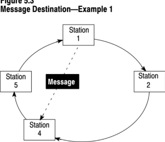
Use a Classic PLC-5 processor (except the PLC-5/10 processor) in adapter mode when you need predictable, real-time exchange of data between a distributed control PLC-5 processor and a supervisory processor. You connect the processors via the remote I/O link (see Figure 1.3). You can monitor status between the supervisory processor and the adapter-mode PLC-5 processor at a consistent rate (i.e., the transmission rate of the remote I/O link is unaffected by programming terminals and other non-control-related communications).
Figure 1.3
AdapterMode Communication
1
Remote I/O Link
1771 I/O DL40Message
Display Remote I/O Link
Supervisory Processor PLC5 Processor in Adapter Mode
1 The following programmable controllers can operate as supervisory processors:
PLC2/20t and PLC2/30t processors PLC3t and PLC3/10t processors
PLC5/11, 5/15, 5/20, 5/25, and 5/30 processors as well as PLC5/VMEt processors PLC5/40, 5/40L, 5/60, 5/60L, and 5/80 processors as well as PLC5/40BVt and PLC5/40LVt processors
PLC5/20Et, 5/40Et
PLC5/250t
All PLC5 family processors, except the PLC5/10, can operate as remote I/O adapter modules.
2
2
The PLC-5 processor in adapter mode acts as a remote station to the supervisory processor. The adapter-mode PLC-5 processor can monitor and control its processor-resident local I/O while communicating with the supervisory processor via a remote I/O link.
The supervisory processor communicates with the PLC-5/12, -5/15, or -5/25 adapter with either eight or four I/O image table words.
A PLC-5 processor transfers I/O data and status data using discrete transfers and block transfers. You can also use block-transfer instructions to communicate information between a supervisory processor and an adapter-mode processor. The maximum capacity per block transfer is 64 words.
Using the Classic PLC5
Processor
Choosing Hardware
Use this chapter to guide you in the selection of system hardware for your application. To select: Go to page: I/O modules 21 I/O adapters 24 Chassis 26 Operator interface 26 PLC5 processor 29 Power supplies 29 Memory modules 213 Batteries 213 Complementary I/O 213 Backup system 214 Termination resistor 215 Cables 215
You select I/O modules to interface your PLC-5 processor with machines or processes that you have previously determined.
Use the following list and Table 2.A as guidelines for selecting I/O modules and/or operator control interface(s).
How much I/O is required to control the process(es)?
Where will you concentrate I/O points for portions of an entire process (when an entire process is distributed over a large physical area)? What type of I/O is required to control the process(es)?
What is the required voltage range for each I/O module? What is the backplane current required for each I/O module? What are the noise and distance limitations for each I/O module? What isolation is required for each I/O module?
Chapter Objectives
Selecting I/O Modules
System Design Determined
Choosing Communication
Transferring Discrete and Block Data
Planning Your System Programs Calculating Program Timing Assigning Addressing Mode, Racks, and Groups Placing System Hardware Choosing Hardware Selecting Interrupt Routines
Table 2.A
Guidelines for Selecting I/O Modules Choose this type of
I/O module: For these types of field devices or operations (examples): Explanation: Discrete input module
and block I/O module1 Selector switches, pushbuttons, photoelectric eyes, limit switches,circuit breakers, proximity switches, level switches, motor starter contacts, relay contacts, thumbwheel switches
Input modules sense ON/OFF or OPENED/ CLOSED signals. Discrete signals can be either ac or dc.
Discrete output module
and block I/O module1 Alarms, control relays, fans, lights, horns, valves, motor starters, solenoids Output module signals interface with ON/OFF orOPENED/CLOSED devices. Discrete signals can be either ac or dc.
Analog input module Temperature transducers, pressure transducers, load cell transducers,
humidity transducers, flow transducers, potentiometers Convert continuous analog signals into inputvalues for PLC processor. Analog output module Analog valves, actuators, chart recorders, electric motor drives,
analog meters Interpret PLC processor output to analog signals(generally through transducers) for field devices. Specialty I/O modules Encoders, flow meters, I/O communication, ASCII, RF type devices,
weigh scales, barcode readers, tag readers, display devices Are generally used for specific applications suchas position control, PID, and external device communication.
1 A 1791 block I/O module is a remote I/O device that has a power supply, remote I/O adapter, signal conditioning circuitry, and I/O connections. A block I/O module does not require a chassis mount. It is used to control concentrated discrete remote I/O such as control panels, pilot lights, and status indications.
Important: Determine addressing in conjunction with I/O module
selection. The selection of addressing and the selection of I/O module density are mutually dependent.
Selecting I/O Module Density
The density of an I/O module is the number of processor input or output image table bits to which it corresponds. A bidirectional module with 8 input bits and 8 output bits has a density of 8. Table 2.B provides guidelines for selecting I/O module density.
Table 2.B
Guidelines for Selecting I/O Module Density Choose this I/O density: If you:
8point I/O module • currently use 8point modules • need integral, separatelyfused outputs • want to minimize cost per module 16point I/O module • currently use 16point modules
• need separately fused outputs with a special wiring arm 32point I/O module • currently use 32point modules
• want to minimize number of modules
• want to minimize the space required for I/O chassis • want to minimize cost per I/O point
Master/Expander I/O Modules
Some I/O modules (called “masters”) communicate with their expanders over the backplane. These master/expander combinations either:
can time-share the backplane, or cannot time-share the backplane
For masters that can time-share the backplane, you can use two masters in the same chassis. For a master/expander combination that cannot
time-share the backplane, you cannot put another master/expander combination in the same I/O chassis.
Example: The stepper-controller module (cat. no. 1771-M1, part of a
1771-QA assembly) and the servo-controller module (cat. no. 1771-M3, part of a 1771-QC assembly) always act as masters and cannot time-share the backplane. Therefore, you cannot put a second master module in the same chassis with either of these modules.
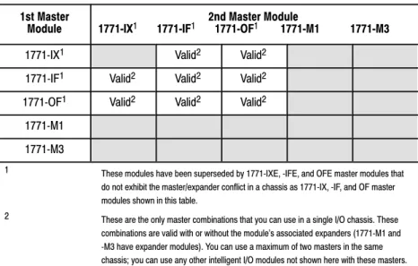
Table 2.C summarizes the compatibility of master modules within a single I/O chassis.
Table 2.C
Compatibility of Master Modules within a Single I/O Chassis 1st Master
Module 2nd Master Module 1771IX1 1771IF1 1771OF1 1771M1 1771M3
1771IX1 Valid2 Valid2
1771IF1 Valid2 Valid2 Valid2 1771OF1 Valid2 Valid2 Valid2
1771M1 1771M3
1 These modules have been superseded by 1771IXE, IFE, and OFE master modules that do not exhibit the master/expander conflict in a chassis as 1771IX, IF, and OF master modules shown in this table.
2 These are the only master combinations that you can use in a single I/O chassis. These combinations are valid with or without the module's associated expanders (1771M1 and M3 have expander modules). You can use a maximum of two masters in the same chassis; you can use any other intelligent I/O modules not shown here with these masters.
Important: Density is not relevant to an expander module because it
communicates only with its master; an expander module does not communicate directly with an adapter.
Select I/O adapter modules to interface your PLC-5 processor with I/O modules. Use Table 2.D as a guide when you select I/O adapter modules.
Table 2.D
Guidelines for Selecting Adapter Modules
Choose: When your requirements are:
1771AS or 1771ASB1 Remote I/O Adapter Module (or 1771AM1, AM2 chassis with integral power supply and adapter module)
a remote I/O link with:
• 57.6 kbps with a distance of up to 10,000 cable feet or
• timing that isn't critical enough to place I/O modules in a processor local I/O chassis or an extendedlocal I/O chassis
1771ALX ExtendedLocal I/O
Adapter Module an extendedlocal I/O link with timing that is critical and all extendedlocalI/O chassis are located within 100 ft of the processor. 11771ASB series C and later have 230.4 kbps communication rate in addition to 57.6 kbps and 115.2 kbps.
17
71AS/ASB Remote I/O Adapter Modules
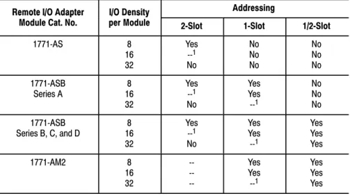
Table 2.E shows the I/O density per module and addressing modes you can use with I/O chassis and remote I/O adapter modules.
Table 2.E
I/O Chassis/Adapter Module Combinations
Remote I/O Adapter I/O Density Addressing
Remote I/O Adapter
Module Cat. No. I/O Densityper Module 2Slot 1Slot 1/2Slot
1771AS 8 16 32 Yes 1 No No No No No No No 1771ASB Series A 168 32 Yes 1 No Yes Yes 1 No No No 1771ASB Series B, C, and D 168 32 Yes 1 No Yes Yes 1 Yes Yes Yes 1771AM2 8 16 32 Yes Yes 1 Yes Yes Yes 1 Conditional module placement; you must use an input module and an output module in two
adjacent slots (even/odd pair) of the I/O chassis beginning with slot 0. If you cannot pair the modules this way, leave the adjacent slot empty.
Using the 1771-ASB Series C or D adapter module, you can choose one of three communication rates: 57.6 kbps, 115.2 kbps, or 230.4 kbps.
Selecting I/O Adapter
Modules
ALX ASB
1771ALX ExtendedLocal I/O Adapter Module
Table 2.F shows the I/O density per module and addressing modes you can use with I/O chassis and extended-local I/O adapter modules.
Table 2.F
I/O Chassis/Extended Local I/O Adapter Module Combinations
Module Cat No I/O Density Addressing
Module Cat. No. per ModuleI/O Density
2Slot 1Slot 1/2Slot
1771ALX Series A 168 32 Yes 1 No Yes Yes 1 Yes Yes Yes 1 Conditional module placement; you must use an input module and an output module in two adjacent slots (even/
odd pair) of the I/O chassis beginning with slot 0. If you cannot pair the modules this way, leave the adjacent slot empty.
Other Devices on an I/O Link
Other devices that you can use on a remote I/O link are: PLC-5 processor in adapter mode
PLC-5/250 remote scanner in adapter mode PLC interface module for digital ac and dc drives remote I/O adapter for Bulletin 1336 drives RediPANELt pushbutton and keypad modules Datalinert
PanelView (see operator interface)
F30D option module (for T30 plant-floor terminal) 8600 or 9/SERIES CNC with remote I/O adapter option CVIMt in adapter mode
Pro-Spect 6000 Fastening System with remote I/O adapter option 1747-DCM module (to SLC-500 rack)
1771-DCM module
1771-GMF robot (remote I/O interface module)
See the appropriate Allen-Bradley product catalog for more information on these devices.
An I/O chassis is a single, compact enclosure for the processor,
power-supply modules, remote and extended-local I/O adapter modules, and I/O modules. The left-most slot of the I/O chassis is reserved for the processor or adapter module. Consider the following when selecting a chassis:
When you determine the maximum number of I/O in your application, allow space for the I/O slots dedicated to power-supply modules, communication modules, and other intelligent I/O modules. You must use series B or later chassis with 16- and 32-point
I/O modules.
Allow space for future addition of I/O modules to chassis.
I/O chassis available are: 4-slot (1771-A1B) 8-slot (1771-A2B)
12-slot—rack mount (1771-A3B), panel mount (1771-A3B1) 16-slot (1771-A4B)
You can also choose a chassis with an integral power supply and remote I/O adapter (show at left). The two types are:
1-slot (1771-AM1) 2-slot (1771-AM2)
PanelView and ControlView are operator interface products or packages that communicate with a PLC-5 processor. Use Table 2.G as a guideline when selecting either PanelView or ControlView for your PLC-5 programmable controller system. Use Table 2.H for a comparison of PanelView and ControlView features.
Selecting I/O Chassis
4-Slot 1771A1B 1771AM1 1771AM2
Selecting an Operator
Interface
Table 2.G
Guidelines for Selecting an Operator Interface Choose this
operator interface: For these types of operations (examples): Explanation: PanelView1 Starts/stops, auto/manual operations,
setpoints, outputs, alarms Used as an operator window to enter commands that make process adjustments suchas starts/stops and loop changes. Can also be used for alarming operations. Can communicate with a single PLC5 processor on a remote I/O link. Has a fixed number of devices and amount of data that it can handle. Has builtin error checking. Is an industrialhardened CRT with pushbuttons, solid state memory and processor, and no moving parts (i.e., disk drive).
Utilizes pass through, which is the ability to download/upload via DH+/remote I/O links. ControlView1 Store, display, and manipulate data
on process performance (i.e., trends, process graphics, formulas, reports, and journals)
Used as an operator window that communicates with a PLC5 processor on Data Highway Plus (DH+) link. Designed for use as an information link. Can communicate to multiple PLC processors. ControlView is a software package that runs on an IBMr
DOSbased personal computer. 1Refer to your local AllenBradley sales office or AllenBradley distributor for more information on PanelView and ControlView.
Table 2.H
Comparison of PanelView and ControlView Features
Category PanelView ControlView
Communication with
PLC processor Remote I/O5 block transfers per terminal maximum (32 words per transfer) 1 discrete transfer per terminal (64 words maximum, one way) This is 8 racks of transfer
DH+ link Data Highway
Data Highway II Native Mode Graphics Character graphics
Create screens with PanelBuilder software
Monochrome or color (8 of 16 colors displayed at a time)
Pixel Graphics
Create screens with Mouse Grafix editor option or C Toolkit EGA, VGA, or equivalent with 256K RAM
Monochrome or color monitor Number of
Screens per Terminal/Workstation
8 to 12 screens of medium complexity typical 200 objects maximum per screen
Limited by terminal memory size: 128 Kbytes
Limited only by hard disk capacity 50 data entry locations per screen 50 tags per command list per screen 300 tags/points maximum per screen Data Capacity 200 objects maximum per screen 10,000 points maximum in database Communication
Rate Limited by blocktransfer and discretetransfer timing Depends on PLC processor and remote I/O link size
8 scan classes, each with userconfigurable foreground and background update times; limited by performance of Data Highway, DH+, or Data Highway II link
Hardware Keypad or Touchscreen terminals, color or monochrome AllenBradley, IBM, or compatible computer required for PanelBuilder software
AB, IBM, or compatible computer with 286 or 386 processor, math coprocessor, hard disk required at each operator station
Programming PanelBuilder software
Menudriven with fillintheblank information entry Use PanelBuilder to create application file that defines screens, messages, alarms, then download application file to PanelView terminal
Create data base online via the menu. Menudriven, fillintheblank information entry, or import data via the ASCII import capability
Create screens with the mouse GRAFIX editor option or C toolkit option
Messages 496 maximum per terminal Not Applicable
Alarms 496 maximum per terminal 2000 points with Alarming option
Security 8 levels 16 levels with individual operator login capability
Individual objects with security Screen lockout
For more information on selecting and configuring PanelView, see: PanelView Operator Terminal and PanelBuilder Development Software
User Manual, cat. no. 2711-ND002 version C, PN40061-139-01— request latest revision
Replacing Node Adapter Firmware for PanelView Terminals Installation Data, PN40062-236-01—request latest revision
For more information on selecting and configuring ControlView, see: ControlView Core User Manual, publication 6190-6.5.1
ControlView Allen-Bradley Drivers User Manual, publication 6190-6.5.5
ControlView Networking User Manual, publication 6190-6.5.9
Other Operator Interfaces
You can use the following as operator interfaces in your PLC-5 processor system:
RediPANEL pushbutton and keypad modules Dataliner
1784-T47 and 1784-T53 programming terminals
See the appropriate Allen-Bradley product catalog for more information on these operator interfaces.
Choose from the following PLC-5 processors. Table 2.I
Classic PLC5 Processor Selection Chart Part 1 Processor/
Cat. No. Maximum UserMemory Words
EEPROM Module Memory (Words) &
Module Number Total I/O Maximum(any mix) AnalogI/O Max Program Scan Time / K Word
I/O Scan time/Rack (in a single Chassis, extlocal or remote) Multiple MCPs / Quantity PLC5/10 (1785LT4) 6 K 8 K (1785MJ) •512 (32I/O modules) •256 (16I/O modules)
•128 (8I/O modules) 256 2 ms (discrete logic)8 ms (typical) N/A No / 1
PLC5/12
(1785LT3) 6 K 8 K (1785MJ)
•512 (32I/O modules)
•256 (16I/O modules)
•128 (8I/O modules) 256 2 ms (discrete logic)8 ms (typical) •10 ms @ 57.6 kbps(remote) No / 1
PLC5/15
(1785LT) 6 K expandableto 10 K or 14 K 8 K (1785MJ)
•512 (any mix) or
•512 in + 512 out
(complementary) 512 2 ms (discrete logic)8 ms (typical) •10 ms @ 57.6 kbps(remote) No / 1
PLC5/25 (1785LT2) 13 K expandable to 17 K or 21 K 8 K (1785MJ) or16 K (1785MK) •1024 (any mix) or •1024 in + 1024 out
(complementary) 1024 2 ms (discrete logic) 8 ms (typical) •10 ms @ 57.6 kbps(remote) No / 1
Table 2.J
Classic PLC5 Processor Selection Chart Part 2 Processor/ Number of Remote I/O Extended Local MaximumNumber of
Maximum Number of I/O
Chassis Number ofRS232/
422/ 423 Remote I/OTransmission BackplaneCurrent Processor/
Cat. No. Number of Remote I/O, ExtendedLocalI/O, and DH+ Ports Number ofI/O Racks Total Ext Local Remote 422/ 423ports TransmissionRates1 CurrentLoad PLC5/10
(1785LT4) •1 DH+ 1 1 0 0 0 2.5A
PLC5/12
(1785LT3) ••1 DH+1 Remote I/O (Adapter Only) 4 1 0 0 0 57.6 kbps 2.5A
PLC5/15
(1785LT) ••1 DH+1 Remote I/O (Adapter or Scanner) 4 13 0 12 0 57.6 kbps 2.5A PLC5/25
(1785LT2) ••1 DH+1 Remote I/O (Adapter or Scanner) 8 17 0 16 0 57.6 kbps 2.5A
Use the following steps as guidelines for selecting a power supply for a chassis that contains a PLC-5 processor, a 1771-AS or -ASB remote I/O adapter module, or a 1771-ALX extended-local I/O adapter module.
1. Determine the input voltage for the power supply.
2. Calculate the total backplane current draw for I/O modules by adding together the backplane current draw for each I/O module in that chassis.
Choosing a Classic PLC5
Processor for Your
Application
3. Add to the total of the I/O module backplane current draw either:
a. 3.3 Amps when the chassis will contain a PLC-5 processor (maximum current draw for any PLC-5 processor) or b. 1.2 Amps when the chassis will contain either a remote I/O
1771-AS or -ASB module or a 1771-ALX extended-local I/O adapter module
4. If you leave slots available in your chassis for future expansion:
a. list backplane current draw for future I/O modules
b. add the total current draw for all expansion I/O modules to the total calculated in step 3.
5. Determine whether the available space for the power supply is in the
chassis or mounted external to the chassis.
Choose your power supply from Table 2.K or Table 2.L using the input voltage requirement and the total backplane current draw as determined in the previous steps, 1 through 5.
See the Automation Products Catalog, publication AP100, for more information on power supplies.
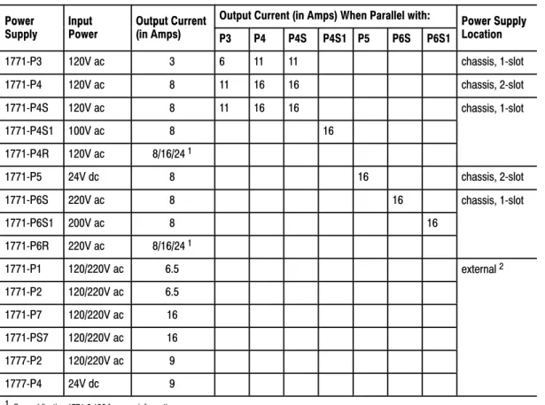
Powering a Chassis Containing a PLC5 Processor
Table 2.K lists the power-supply modules that you can use with a Classic PLC-5 processor.
Table 2.K
Powering a Chassis Containing a Classic PLC5 processor
Power Input Output Current Output Current (in Amps) When Parallel with: Power Supply Power
Supply Input Power Output Current(in Amps) P3 P4 P4S P4S1 P5 P6S P6S1 Power SupplyLocation
1771P3 120V ac 3 6 11 11 chassis, 1slot 1771P4 120V ac 8 11 16 16 chassis, 2slot 1771P4S 120V ac 8 11 16 16 chassis, 1slot 1771P4S1 100V ac 8 16 1771P4R 120V ac 8/16/241 1771P5 24V dc 8 16 chassis, 2slot 1771P6S 220V ac 8 16 chassis, 1slot 1771P6S1 200V ac 8 16 1771P6R 220V ac 8/16/241 1771P7 120/220V ac 16 external2 1771PS7 120/220V ac 16 1See publication 17712.136 for more information.
2 You cannot use an external power supply and a slotbased power supply module to power the same chassis; they are not compatible.
Powering a Remote I/O Chassis Containing a 1771AS or 1771ASB or
an ExtendedLocal I/O Chassis Containing a 1771ALX
Table 2.L lists the power supply modules that you can use with a remote I/O chassis or an extended-local I/O chassis.
Table 2.L
Powering a Remote I/O Chassis (Containing a 1771AS or ASB) or an ExtendedLocal I/O Chassis (Containing a 1771ALX)
Power Input Output Current Output Current (in Amps) When Parallel with: Power Supply Power
Supply Input Power Output Current(in Amps) P3 P4 P4S P4S1 P5 P6S P6S1 Power SupplyLocation
1771P3 120V ac 3 6 11 11 chassis, 1slot 1771P4 120V ac 8 11 16 16 chassis, 2slot 1771P4S 120V ac 8 11 16 16 chassis, 1slot 1771P4S1 100V ac 8 16 1771P4R 120V ac 8/16/24 1 1771P5 24V dc 8 16 chassis, 2slot 1771P6S 220V ac 8 16 chassis, 1slot 1771P6S1 200V ac 8 16 1771P6R 220V ac 8/16/24 1 1771P1 120/220V ac 6.5 external 2 1771P2 120/220V ac 6.5 1771P7 120/220V ac 16 1771PS7 120/220V ac 16 1777P2 120/220V ac 9 1777P4 24V dc 9
1 See publication 17712.136 for more information.
2 You cannot use an external power supply and a slotbased power supply module to power the same chassis; they are not compatible.
Select a memory module from Table 2.M for your PLC-5 processor. Table 2.M
PLC5 Processor Memory Modules
Nonvolatile Memory Backup (EEPROM) RAM Memory (CMOS)
Words Catalog Number (and Processor) Words Catalog Number (and Processor)
8 K 1785MJ 4 K 1785MR (PLC5/15 and 5/25)
16 K 1785MK (PLC5/25) 8 K 1785MS (PLC5/15 and 5/25) A battery ships with your PLC-5 processor. Select a replacement battery using Table 2.N and Table 2.O. See the Allen-Bradley Guidelines for Handling Lithium Batteries, publication ICCG-5.14, for more information.
Table 2.N
Processor Batteries
Processor Battery1 Function
PLC5/10, 5/12, 5/15,
and 5/25 1770XY, AAlithium Retains the processor memory and thememory in an optional CMOS RAM module if the processor is not powered.
1 The 1770XY is a 3.6 Volt AA size lithium thionyl chloride battery manufactured by Tadiran as their part number TL 5104 and type AEL/S.
Table 2.O
Average Battery Life
Battery Temperature Power Off 100%
(Average) Power Off 50%(Average) 1770XY 60° C
25° C 329 days 2 years 1.4 years3.3 years
You configure complementary I/O by assigning an I/O rack number of one I/O chassis (primary) to another I/O chassis (complementary). You
complement I/O functions in the primary chassis with opposite functions in the complementary chassis. Use chapter 4, “Assigning Addressing Mode, Racks, and Groups,” in conjunction with the following selection of complementary I/O hardware.
Selecting Memory Modules
Selecting a Replacement
Battery
Selecting
Use the following modules in either primary or complementary I/O chassis opposite any type of module:
Communication Adapter Module (1771-KA2) Communication Controller Module (1771-KE)
PLC-2 Family/RS-232-C Interface Module (1771-KG) Fiber Optics Converter Module (1771-AF)
DH/DH+ Communication Adapter Module (1785-KA) DH+/RS-232C Communications Interface Module (1785-KE)
Use the following modules in either primary or complementary I/O chassis opposite any type of module. However, these modules do not work as standalone modules; each one has an associated master module. Use care when placing the master modules in the I/O chassis (refer to the paragraph on Master/Expander I/O modules):
Analog Input Expander Module (1771-E1, -E2, -E3) Analog Output Expander Module (1771-E4)
Servo (Encoder Feedback) Expander Module (1771-ES) Pulse Output Expander Module (1771-OJ)
A PLC-5 processor backup system contains two of each of the following hardware components:
Classic PLC-5 processor module Processor Catalog Number PLC5/15 1785LT Series B PLC5/25 1785LT2
1785-BCM Series C Backup Control Module (for 2 channels) 1785-BEM Backup Expansion Module (for 2 additional channels) Power supply
Local chassis
Important: The PLC-5 backup system does not back up I/O in the resident local chassis. Do not install I/O in the processor-resident local chassis of a backed up system.
Refer to the PLC-5 Backup Communication Module User Manual, publication 1785-6.5.4, for more information on configuring a PLC-5 processor backup system.
Selecting a PLC5 Processor
Backup System
Terminate remote I/O links by setting switch assembly SW3. If you cannot use an 82-Ohm terminator because of devices that you place on your I/O link (see the table below for a list of these devices), you must use 150-Ohm terminators. Using the higher resistance reduces the quantity of devices to 16 that you can place per remote I/O link. Also, this limits your
communication rates to 57.6 kbps and 115.2 kbps.
DH+ Network Terminator
Terminate your DH+ network with a 150-Ohm, 1/2-watt terminator. If you have this processor: Terminate a DH+ link by:
PLC5/10, 5/12, 5/15, or 5/25 Setting switch assembly SW3 of the PLC5 processor (refer to your Classic 1785 PLC5 Family Programmable Controllers Hardware Installation Manual, publication 17856.6.1).
Connect the programming terminal directly to the processor through the D-shell DH+ COMM INTFC connector on the front panel. You can also connect the programming terminal remotely to a DH+ link through the 3-pin connector or at a remote station.
Select cables from the options listed below. See chapter 3, “Placing System Hardware,” to determine the lengths that you will need for cables in your system.
Remote I/O Link
Use Belden 9463 twinaxial cable (1770-CD) to connect your PLC-5 processor to remote I/O adapter modules.
Connect your I/O devices using:
single-conductor wire (analog and some discrete applications) multi-conductor cable (analog and some discrete applications) multi-conductor shielded cable (some specialty I/O modules and
low-voltage dc discrete modules)
Selecting Link Terminators
Connecting a
Programming Terminal to a
Processor Module
See the Classic 1785 PLC-5 Programmable Controllers Hardware Installation Manual, publication 1785-6.6.1, and the installation data for the I/O modules that you have selected for more information on I/O wiring. Also, see Allen-Bradley Programmable Controller Wiring and Grounding Guidelines, publication 1770-4.1, and Control, Communication and
Information Reference Guide, publication ICCG-1.2, for more information.
Programming Terminal
The cable that you use to connect a processor to a programming terminal depends on the communication device used. Table 2.P lists the cables that you need for different configurations.
Table 2.P
Cables for Connecting a Classic PLC5 Processor and Programming Terminal
If you have this device: With this
communication device: Use this cable: PLC5/10, 5/12, 5/15, 1784KT, KT2 1784CP PLC 5/10, 5/12, 5/15, or 5/25 1784 KT, KT21784KL, KL/B 1784 CP 1784KTK1 1784CP5 1784PCMK 1784PCM5 6160T60, 6160T70, 6121
IBM PC/AT (or compatible) 1785KE 1784CAK 1784T47, 6123, 6124
IBM PC/XT (or compatible) 1785KE 1784CXK
6120, 6122 1785KE 1784CYK
You can also use a 1770-KF2/B communication interface to connect to a PLC-5 processor. You build your own cables to connect your
programming terminal via the COM1 or COM2 serial ports to the 1770-KF2/B. For the cable pin assignments, see the Classic 1785 PLC-5 Programmable Controller Hardware Installation Manual, publication 1785-6.6.1.
Placing System Hardware
A well-planned layout is essential to the proper installation of your Classic PLC-5 programmable controller system. Read this chapter for information on placing hardware.
If you want to read about: Go to page:
Proper environment 31 Protecting your system 34
Avoiding electrostatic damage 34
Planning your raceway layout 34
Planning your cabling 36
Grounding your system 37
Place the processor in an environment with conditions that fall within the guidelines described in Table 3.A.
Table 3.A
Proper Environmental Conditions For Your Processor Environmental Condition Acceptable Range
Operating temperature 0 to 60° C (32 to 140° F) Storage temperature 40 to 85° C (40 to 185° F) Relative humidity 5 to 95% (without condensation)
Separate your programmable controller system from other equipment and plant walls to allow for convection cooling. Convection cooling draws a vertical column of air upward over the processor. This cooling air must not exceed 60° C (140° F) at any point immediately below the processor. If the air temperature exceeds 60° C, install fans that bring in filtered air or recirculate internal air inside the enclosure, or install air-conditioning/heat-exchanger units.
Chapter Objectives
Determining the Proper
Environment
System Design Determined Choosing Communication Transferring Discrete and Block DataPlanning Your System Programs Calculating Program Timing Assigning Addressing Mode, Racks, and Groups Choosing Hardware Placing System Hardware Selecting Interrupt Routines
To allow for proper convection cooling in enclosures containing a
processor-resident chassis and remote I/O chassis, follow these guidelines.
Area reserved for disconnect. transformer, control relays, motor
starters or other user devices.
13081
Minimum spacing requirements for a processorresident chassis: • Mount the I/O chassis horizontally.
• Allow 153 mm (6 in) above and below the chassis.
• Allow 102 mm (4 in) on the sides of each chassis.
• Allow 51 mm (2 in) vertically and horizontally between any chassis and the wiring duct or terminal strips.
• Leave any excess space at the top of the enclosure, where the temperature is the highest.
102mm (4") 153mm (6") 51mm (2") 102mm (4") Wiring Duct 153mm (6") 51mm(2")
(4")
Wiring Duct Wiring Duct
(6")
1 8 7 4 9
Minimum spacing requirements for a remote I/O chassis:
• Mount the I/O chassis horizontally.
• Allow 153 mm (6 in) above and below all chassis. When you use more than one chassis in the same area, allow 152.4 mm (6 in) between each chassis.
• Allow 102 mm (4 in) on the sides of each chassis. When you use more than one chassis in the same area, allow 101.6 mm (4 in) between each chassis.
• Allow 51 mm (2 in) vertically and horizontally between any chassis and the wiring duct or terminal strips.
• Leave any excess space at the top of the enclosure, where the temperature is the highest.
Area reserved for disconnect. transformer, control relays, mot or
starters or other user devices.
102mm 153mm 51mm (2") 51mm (2") 153mm (6") (4") 102mm (4") 102mm 153mm (6")
You provide the enclosure for your processor system. This enclosure protects your processor system from atmospheric contaminants such as oil, moisture, dust, corrosive vapors, or other harmful airborne substances. To help guard against EMI/RFI, we recommend a steel enclosure.
Mount the enclosure in a position where you can fully open the doors. You need easy access to processor wiring and related components so that troubleshooting is convenient.
When you choose the enclosure size, allow extra space for transformers, fusing, disconnect switch, master control relay, and terminal strips.
ATTENTION: Under some conditions, electrostatic
discharge can degrade performance or damage the processor module. Read and observe the following precautions to guard against electrostatic damage.
Wear an approved wrist strap grounding device when handling the processor module.
Touch a grounded object to discharge yourself before handling the processor module.
Do not touch the backplane connector or connector pins. When not handling the processor module, keep it in its
protective packaging.
The raceway layout of a system reflects where the different types of I/O modules are placed in I/O chassis. Therefore, you should determine I/O-module placement prior to any layout and routing of wires. When planning your I/O-module placement, however, segregate the modules based on the conductor categories published for each I/O module so that you can follow these guidelines. These guidelines coincide with the guidelines for “the installation of electrical equipment to minimize electrical noise inputs to controllers from external sources” in IEEE standard 518-1982.
Protecting Your Processor
Avoiding Electrostatic
Damage
Laying Out Your
Cable Raceway
To plan a raceway layout, do the following: categorize conductor cables
route conductor cables
Categorize Conductors
Segregate all wires and cables into categories as described in the Industrial Automation Wiring and Grounding Guidelines, publication 1770-4.1. See the installation data for each I/O module that you are using for information about its classification.
Route Conductors
To guard against coupling noise from one conductor to another, follow the general guidelines for routing cables described in the Industrial
Automation Wiring and Grounding Guidelines, publication 1770-4.1. You should follow the safe grounding and wiring practices called out in the National Electrical Code (NEC, published by the National Fire Protection Association, in Quincy, Massachusetts), and local electrical codes.
DH+ Link Cabling
At a DH+ transmission rate of 57.6 kbps, do not exceed 3,048 cable-m (10,000 cable-ft) for a trunkline cable length or 30.5 cable-m (100 cable-ft) for a dropline cable length.
Remote I/O Link Cabling
Refer to Table 3.B for remote I/O link trunkline cable length restrictions. Table 3.B
Maximum Cable Lengths per Communication Rate Transmission Rate Maximum Cable Length
57.6 kbps 3,048 m (10,000 ft) 115.2 kbps 1,524 m (5000 ft) 230.4 kbps 762 m (2500 ft)
Important: All devices on the remote I/O link must be communicating at
the same transmission rate.
Use 6.35 mm (0.25 inch) mounting bolts to attach the I/O chassis to the enclosure backpanel.
Figure 3.1
Chassis Dimensions (Series B)
315mm (12.41") Power Connector 254mm (10") Side 193mm1 (7.60") 591mm (23.25") 464mm (18.25") 337mm (13.25") 210mm (8.25") 171mm (6.75") 610mm (24.01") 483mm (19.01") 356mm (14.01") 229mm (9.01") 16slot 1771A4B 12slot 1771A3B1 8slot 1771A2B 4slot 1771A1B 16slot 1771 12slot 8slot 4slot 1771A1B 1771A2B 1771A3B1 1771A4B Front 12450I 217mm1 (8.54") 339mm (13.53") 465mm (18.31") 484mm (19") 9mm(.34") 26mm (1.02") 178mm (7") 130mm (5.10") 1Total maximum depth dimension per installation will be dependent upon module wiring and connectors. 1771A3B
Side
Laying Out the
Backpanel Spacing
Figure 3.2
I/O Chassis and 1771P2 Power Supply Dimensions
315mm (12.41") 610mm (24.01") 16-slot 1771-A4B 483mm (19.01") 356mm 12-slot 1771-A3B1 (14.01") 229mm (9.01") 8-slot 1771-A2B 4-slot 1771-A1B 254mm (10") 12-slot 8-slot 4-slot 16-slot 1771P1 1771P2 1771P7 1771PS7 Power Supply Use .25" dia mounting bolts (4 places) 12451I 91mm (3.6") 591mm (23.25") 464mm (18.25") 337mm (13.25") 210mm (8.25")
Clearance depth is 204 mm (8 in) for 8 I/O connection points per module.
See Figure 3.3 for the recommended grounding configuration for remote I/O systems.
Figure 3.3
Recommended Grounding Configuration for Remote I/O Systems
Enclosure
Grounding Electrode Conductor To Grounding
Electrode System Ground
Bus
I/O Chassis Wall
Ground Lug Nut Star Washer Ground Lug
Grounding Configuration
Assigning Addressing Modes,
Racks, and Groups
This chapter conveys basic hardware addressing concepts and gives you guidelines with which to choose the addressing modes (including complementary I/O), racks, and groups to use in your system.
If you want to read about: Go to page:
Placing I/O modules in chassis 41 Understanding terms 42
Choosing I/O addressing mode 43
Rack number assignments 49
Addressing complementary I/O 412
Place I/O modules in a chassis depending on the electrical characteristics of the modules. The placement is made left to right, with the left-most position being closest in the chassis to the PLC-5 processor or the I/O adapter module. The placement order is as follows:
1. block-transfer modules (all types)
2. dc input modules, placed left to right from lowest to highest voltages 3. dc output modules, placed left to right from lowest to highest voltages 4. ac input modules, placed left to right from lowest to highest voltages 5. ac output modules, placed left to right from lowest to highest voltages
Chapter Objectives
Placing I/O Modules
in Chassis
System Design Determined Choosing Communication Transferring Discrete and Block DataPlanning Your System Programs Calculating Program Timing Assigning Addressing Mode, Racks, and Groups Choosing Hardware Placing System Hardware Selecting Interrupt Routines
The following guidelines are for placing block-transfer modules. Place as many modules as possible for which you need fast
block-transfer times in your processor-resident local I/O chassis . Place modules that need fast block-transfer times (but space is not
available in processor-resident local I/O chassis) in an extended-local I/O chassis.
Place modules in which timing is not as critical as in other block-transfer modules in remote I/O chassis.
ac output modules should always be the furthest I/O modules from any block-transfer modules in the same chassis.
Become familiar with the following terms and their definitions: An I/O group is an addressing unit that corresponds to an input
image-table word (16 bits) and an output image-table word (16 bits). An I/O group can contain up to 16 inputs and 16 outputs; and it can occupy 2-, 1-, or 1/2-module slots for addressing purposes.
00 01 02 03 04 05 06 07 10 11 12 13 14 15 16 17 00 01 02 03 04 05 06 07 10 11 12 13 14 15 16 17 00 01 02 03 04 05 06 07 10 11 12 13 14 15 16 17 13073 (I/O Group #0) (I/O Group #0) 2Slot I/O Module Group 1Slot I/O Module Group Input
Terminals OutputTerminals
Output or Input Terminals
Understanding the Terms
Used in this Chapter
An I/O rack is an addressing unit that corresponds to 8 input image-table words and 8 output image-table words. A rack contains 8 I/O groups.
13074
0 1 2 3 4 5 6 7
I/O Group Numbers.
Depending on I/O chassis size and I/O group size, an I/O rack can occupy a fraction of an I/O chassis, a full I/O chassis, or multiple I/O chassis.
Select an addressing mode for each chassis independently, based on the type and density of the I/O modules contained therein. When you select addressing mode, limit the number of remote I/O adapters and I/O modules to the maximum number that the PLC-5 processor can support.
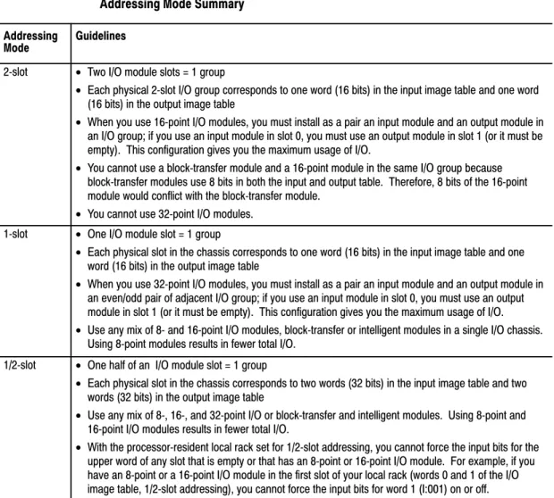
Using 2Slot Addressing
When you select 2-slot addressing, the processor addresses two I/O module slots as one I/O group. Each physical 2-slot I/O group corresponds to one word (16 bits) in the input image table and one word (16 bits) in the output image table. The type (unidirectional or bidirectional) and density of a module that you install determines the number of bits that are used in each word.
Important: You cannot use 32-point I/O modules with 2-slot addressing.
Choosing the
8-Point I/O Modules
Eight-point digital discrete I/O modules have a maximum of eight inputs or up to eight outputs. Because they do not interfere with each other’s I/O image, you can place any mix of 8-point I/O modules (including bidirectional modules, such as block-transfer modules) in any order.
00 01 02 03 04 05 06 07 10 11 12 13 14 15 16 17 17 16 15 14 13 12 11 10 07 06 05 04 03 02 01 00 17 16 15 14 13 12 11 10 07 06 05 04 03 02 01 00 14965
2Slot I/O Group with One 8pt Input Module and One 8pt Output Module
This I/O group uses 8 bits of the input image table and 8 bits of the output image table.
Output Terminals Input Terminals 2-Slot I/O Group
Output ImageTable Word Corresponding to the I/O Group.
Input ImageTable Word Corresponding to the I/O Group. Unused
Output Bits Used
Input Bits Used Always 0 00 01 02 03 04 05 06 07 10 11 12 13 14 15 16 17 17 16 15 14 13 12 11 10 07 06 05 04 03 02 01 00 17 16 15 14 13 12 11 10 07 06 05 04 03 02 01 00 2-Slot I/O Group 11867
2Slot I/O Group with Two 8pt Input Modules
This I/O group uses 16 bits of the input image table.
Input
Terminals InputTerminals
Output ImageTable Word Corresponding to the I/O Group.
Input ImageTable Word Corresponding to the I/O Group. Unused
16-Point I/O Modules
Sixteen-point digital discrete I/O modules have up to 16 inputs or up to 16outputs. A 16-point I/O module uses a full word in the input or output image table. 17 16 15 14 13 12 11 10 07 06 05 04 03 02 01 00 17 16 15 14 13 12 11 10 07 06 05 04 03 02 01 00 00 01 02 03 04 05 06 07 10 11 12 13 14 15 16 17 00 01 02 03 04 05 06 07 10 11 12 13 14 15 16 17 15559
This I/O group uses 16 bits of the input image table and 16 bits of the output image table.
2Slot I/O Group with One 16pt Input Module and One 16pt Output Module
Output Terminals Input Terminals 2-Slot I/O Group
Output ImageTable Word Corresponding to the I/O Group.
Input ImageTable Word Corresponding to the I/O Group.
Because each 16pt module uses a full word in the image table, the only type of module that you can install in a 2slot I/O group with a 16pt input module is an 8 or 16pt output module that performs a complementary function (inputs and outputs complement each other). Since all blocktransfer modules are bidirectional, they cannot be used to complement either input or output modules. I O I O I O I O I O I O I O I O 0 1 2 3 4 5 6 7 0 1 2 3 4 5 6 7
0 1 2 3 4 5 6 7 I/O Group Designation
Input/Output Designation I/O Chassis Containing 16pt Modules
Output Image Table
Input Image Table Word #