Privacy Preservation with Scaled Channel–based
Jamming for Data Aggregation in Smart Grids
Chan Dai Truyen Thai, Jong Yeol Ryu, Jemin Lee, Tony Q.S. Quek
Singapore University of Technology and Design, Singapore
Email:
{
thai truyen, jongyeol ryu, jemin lee, tonyquek
}
@sutd.edu.sg
Abstract—In smart grid, the local data aggregator of an area collects the total electrical consumption of the area by aggregating the measurements of smart meters (SMs). A great number of schemes based on the cryptography have been proposed to guarantee the privacy of the individual measurements of the SMs. However, the cryptographic systems require the compli-cated computations and key-management infrastructural support as well as introduce information leaking risks. Therefore, in this paper, we propose a novel physical channel-based scheme for privacy preservation in data aggregation, which can work without a cryptographic system. The SMs preserve the privacy of the measurements by adding the jamming signals, which are constructed by scaled channels.The jamming signals are designed to be cancelled with each other at the aggregator. Concurrently, our scheme can resist different types of attacks such as eavesdrop-ping, compromising, and differential attacks even in the case that they are colluding. The simulation results show that the mean squared error (MSE) of the total measurements is significantly lower than that of the traditional scheme while the privacy of the individual measurements is high.
Index Terms—Smart grid, data aggregation, smart meter, privacy preservation
I. INTRODUCTION
The key characteristic of the smart grid, the next generation of the electrical power grid, is the two–way flow of both electricity and control information. The smart grid is expected to provide reliable, efficient, and sustainable electrical sources with decentralized controlling and consumer involvement [1], [2]. In order to balance the supply and demand as well as efficiently troubleshoot the instantaneous problems in the network, the information exchange and supervision must be guaranteed in an almost real-time manner. Advanced Metering Infrastructure (AMI), which is one of the most important component to realize this function in smart grid, is responsible to collect, measure, and analyze energy consumption [3].
Recently, in the AMI, the SMs have been extensively studied in several disciplines of both academia and industry. The governments of several countries in Europe and North America have recommended to use SMs for households [4], [5]. All electrical appliances in a residential unit (RU) are usually connected to a SM, which acts as a central element to pe-riodically report the power consumption to a local aggregator. This aggregator collects the reports of the RUs in the area and calculates the total consumption of the area and they reports the total consumption to the controller of the network for further analysis and processing. Collected information is used for timely monitoring and analyzing the health of the
electrical grid e.g., making real-time power pricing decisions, and detecting power fraud, or leakage [3], [6], [7].
In a data aggregating system, when the SMs send reports to the local aggregator, the malicious agents can eavesdrop the transmissions and analyze the behaviors and habits of the people living in a certain RU. The security issue becomes one of the most challenging issues of the smart grid. A myriad of electric appliances (e.g., bulb lights, water heaters, hot furnaces, refrigerators, and air conditioners) can be easily analyzed by appliance load monitoring without using any advanced tool [5]. For example, a murderer can determine whether a person is cooking in the kitchen based on his habitual electrical consumption and the current SM’s report [8]. As a result, guaranteeing the privacy of the individual meter readings and, in the mean time, allowing the operation centers to obtain overall information are two important tasks for security in smart grid [4], [9], [10].
In smart grid, the privacy preservation for data aggregation has been studied for years. A great number of works use Paillier cryptosystem, which is a homomormic encryption technique [6]. It allows one to compute the encryption of
s1+s2given only the public-key and the encryption ofs1and s2. Nevertheless, a cryptographic solution, in which Paillier
cryptosystem is an example, normallly requires a complicated initialization phase to exchange the information among the nodes for building the pre-shared keys [4] and an infrastructure to manage these keys. Therefore, the process of cryptosystem not only is computationally expensive but also exposes to information leaking risks.
S1
E2
S3
S5
Aggregator S4
(compromised)
Wireless channel Wireless channel with reporting direction
E1
S2
Compromised data Eavesdropped data
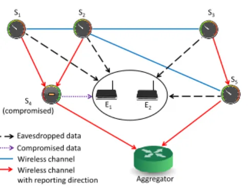
Fig. 1. The system model
eavesdropping from estimating the individual measurement of the target SM. Even in the case that the adjacent SMs of the target SM are compromised, the measurement of the target SM is still confidential since it is still masked by the jamming signals which are based on the channels between the target SM and its non-compromised linked SMs.
II. SYSTEMMODEL
We consider an area with N residential units (RUs) and a single aggregator as shown in Fig. 1. There is one SM in each RU denoted as Si, i ∈ {1,2, ..., N}. We refer
Si (i = 1,· · · , N) and the aggregator as legitimate nodes,
where the aggregator is the (N + 1)-th node and denoted by SN+1. The set of all indices of the legitimate nodes is
defined by S = {1, ..., N + 1}. For the period of t sec, which is referred to the reporting resolution, the electricity consumption of the i-th RU is defined bysi. We assume that
the electricity consumptions of all RUs are distributed with the same distribution and the same variance of ξ2. The local aggregator collects the total electricity consumption of all RSs in the area,sS=P
N
i=1si, but not the individual consumption
of each RU, si,i= 1,· · ·, N.
In the data aggregating system, the malicious agents try to get the electricity consumption of a certain SM, called target SM, denote by sχ, χ∈ {1, ..., N}. For the malicious agents,
we consider two cases of adversary as follows:
• Colluding eavesdroppers: NE colluding eavesdroppers, Ei,i∈ E, whereE is the set of the indices of the
eaves-droppers, listen to all transmissions from the legitimate nodes. The eavesdroppers jointly estimate sχ from all
received signals.
• Colluding eavesdroppers with compromised SMs: NC SMs are compromised by the malicious agent and thus, the eavesdroppers can access to the compromised SMs and obtain their measurements, the information of the linked channels with the compromised SMs, and the received signals at the compromised SMs. The eaves-droppers jointly estimate sχ based on the information
obtained from NC compromised SMs as well as the received signals of NE eavesdroppers. We assume that the target SM is not compromised, i.e., χ /∈ SC, where
SCis the set of the indices of the compromised SMs.
In the data aggregating system, we assume that SMs and eavesdroppers are uniformly distributed in a square of a×a
(m2)and the aggregator is located in the center of the square. We also assume that if the distance between Siand Sj,di,j, is
shorter than a threshold distance given bydo, i.e., di,j ≤do,
then Si and Sj can communicate with each other via a direct
channel given by hi,j = f d− l/2
i,j , where f ∈ CN(0,1) is a
fading coefficient andlis a path-loss exponent. The set of the indices of the legitimated nodes that can directly communicate with Si is defined by Li = {j|di,j ≤ do,∀ j 6= i}.
Otherwise, they cannot directly communicate with each other and hence, the channel between them can be negligible due to the large distance. The channel from Si to Ej is defined
by gi,j = fd˜ −l/2
i,j , where d˜i,j is the distance between Si
and Ej. As the worst case, we assume that the eavesdroppers
can perfectly collude and hence, they can jointly estimate the data based on the received signals of all eavesdroppers. Each legitimate node is assumed to perfectly estimate the directly connected channels. The distances between legitimate nodes are publicly known by all nodes including the eavesdroppers. We only consider the connected network, i.e., there exists at least one path from all SMs to the aggregator and thus, the reports of all SMs can be forwarded to the aggregator The expected transmit power of all nodes is 1 and all transmissions are conducted with a 1-Hz bandwidth.
III. PRIVACYPRESERVING WITHSCALED
CHANNEL–BASEDJAMMING
The proposed privacy–preserving scheme for the data ag-gregation consists of two phases, which is the initialization phase and data aggregation phase with added scaled channels.
A. Initialization Phase
In the initialization phase, each SM determines the data routing path to the aggregator and the channel variances and routing path of all SMs are disseminated to all nodes. The disseminated information can also be received at the eavesdroppers. For the data aggregating system, the schedule of the data reporting of SMs is obtained based on the routing paths of SMs. This phase is performed only when a network of SMs is newly installed. The details of the initialization phase is given as follows:
• Step 1) Each SM determines the linked nodes that can directly communicate with each other such as di,j ≤
do,∀ i= 1,· · · , N.
• Step 2) For each SM, the routing path, which has the least number of hops to the aggregator, is determined based on Dijkstra algorithm [12], [13]. Instead of the original Dijkstra algorithm, which finds the shortest path, we modify the weight of a link to 1 +di,j, where is
a small value such as 1. We can use to find the shortest path among the paths that have the same number of hops.
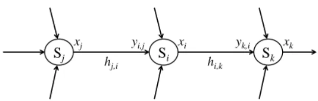
Sj Si Sk
xj yi,j xi yk,i xk hj,i hi,k
Fig. 2. A part of the reporting tree where Sjand Siare respectively child
nodes of Siand Sk.
node of Sj and Sj is a parent node of Si. An example
of reporting tree is shown in Fig. 1 with branches of red arrows. In Fig. 1, S1 sends s1 to S4; and S4 relays it
towards the aggregator. Hence, S1is the child node of S4
and S4 is the parent node of S1.
• Step 4) For the data aggregating system, the reporting schedule is determined by the reporting tree. The main scheduling rule is that a parent node cannot transmit data before its child node transmits data. This rule guarantees that all reports from the SMs are forwarded to the root node using the minimum number of time slots. For example, in Fig. 1), S4 cannot transmit data to the
aggregator before S1 and S2 transmit their data to S4.
Similarly, S5 cannot transmit data earlier than S3. Since
the reporting schedule obtained by this rule is not unique (eg. 1-2-4-3-5 and 3-5-1-2-4 in Fig. 1), we can choose any one of them.
When a node joins or leaves the network, the initialization phase has to be updated for the successful data aggregating.
B. Data Aggregation Phase with Scaled Channel based Jam-ming
After the initialization phase, each SM reports its data at each time slot based on the reporting schedule. Without loss of generality, we assume that the reporting schedule for SMs is 1-2-3-...-N.
In order to preserve the privacy of the reporting data, we propose the scaled channel–based jamming scheme at each SM. Different from the perturbation schemes, which add the random noise, to guarantee the privacy, each SM adds the scaled sum of the connected channels to the measured data. Since the jamming signals, which are the scaled sum of the connected channels, are designed to be cancelled with each other at the aggregator, the aggregator can obtain the total reported data of SMs without jamming signals. However, the eavesdroppers receive the signals, which include the jamming signals.
Let Sj be a child node of Si and Si be a child node of Sk
as shown in Fig. 2. In the j-th time slot, Sj transmits xj to
Si. Then, the received signal at Si is given by
yi,j=hj,ixj+zi,j, (1)
wherezi,jis the noise at Si in thej-th time slot. Siestimates
the data of Sjfrom the received signal, then the estimated data
of Sj at Si is given by
ˆ
uj= √
αjh−j,i1yi,j = √
αj xj+h−j,i1zi,j
, (2)
whereαjis the transmit power scaling factor at Sjto guarantee
that the expected transmit power of Sj is 1.
In the i-th time slot, Si designs the transmit signal ui to
relay the received data and transmit its own data,si, as
ui=si+
X
v∈Ci
ˆ
uv+Ji, (3)
where Ci is the set of the indices of all child nodes of Si.
Here, Si adds the jamming signalJi to the transmit signal to
preserve privacy. The jamming signal at Si is designed by
Ji=β
X
v∈Li
(−1)τ(i,v)hi,v, (4)
where Li is the index set of linked nodes to Si, β is a
coefficient for adjusting the power of the jamming signals created by the channels, and
τ(i, v) =
0, ifi < v,
1, ifi > v, . (5)
Based onτ(i, v), the jamming signal at Sj,Jj contains−hi,j
and Ji contains hi,j. Hence, they can be cancelled at the
aggregator. After power scaling, the transmit signal of Si is
given by
xi= 1
√
αi
ui. (6)
Then, the received signal at Sk is given by
yk,i=hi,kxi+zk,i, (7)
and the estimated data of Si at Sk is given by
ˆ
ui= √
αih−i,k1yk,i= √
αi
xi+h−i,k1zk,i
(8)
=si+
X
v∈Ci
ˆ
xv+Ji+ √
αih−i,k1zk,i. (9)
The transmit signal of Sk is given by
uk=sk+
X
v∈Ck
ˆ
uv+Jk. (10)
LetDk be a set of the indices of all descendant nodes of Sk,
(e.g., child nodes of Sk and child nodes of Sk’s child nodes
and so on), and referred to as the descendant set of Sk. Then,
substituting (8) into (10), the transmit signal in (10) can be rewritten by
uk =
X
v1∈Dek
sv1+β
X
v2∈Dek,v3∈/Dek
I(v2, v3)
| {z }
residual jamming signals
+ X
v4∈Dk √
αv4h
−1
v4,p(v4)zp(v4),v4
| {z }
distortion of estimation
, (11)
where I(k, v), (−1)τ(k,v)h
k,v, Dek = Dk ∪ {k} andp(v4)
is the index of the parent node of thev4-th SM. In (11), the
second term denotes the residual jamming signal at Si. Ifv2∈
e
and −hv2,v3. Hence, they are cancelled out at Sk. However,
if v2 ∈Dek andv3 ∈/ Dek, the jamming signal contains only
hv2,v3 or−hv2,v3 and thus, it cannot be cancelled and remains
as the residual jamming signal at Sk. The third term of (11)
is the distortion of estimation, which is caused by noise. The transmitted signal of Sk is given byxk = √1α
kuk where the
power scaling factor is given by
αk =
Dek
ξ
2+β2 X
v2∈Dek,v3∈/Dek
1
dl v2,v3
+σ2 X
v4∈Dk
αv4 |hv4,p(v4)|
2.
(12)
Since the report tree is known by all legitimate nodes, the power scaling factors of all nodes are known and used to estimate in each step.
Consequently, since the jamming signals are cancelled at the aggregator, the aggregated data at the aggregator can be represented by
ˆ
sS= n
X
v=1
sv+ √
αv4h
−1
v,p(v)zp(v),v
=sS+ ˜z, (13)
where ˆsS is the total electricity consumption of the area and z , Pn
v=1
√
αvh−v,p1(v)zp(v),v is the distortion of the
estimation. The mean squared error of the total consumption in the area of the proposed scheme is obtained by
ePS=E
h
|sS−ˆsS|
2i
=σ2
n
X
v=1
αvdlv,p(v). (14)
In the proposed privacy–preserving scheme, each SM uses the information of the connected channels as the jamming signal. The eavesdroppers do not know the exact value of these channels and hence, they cannot use differential attacks.1
IV. PRIVACYATTACK OFMALICIOUSAGENTS
In this section, we analyze the data estimation of the target SM, Sχ, at the malicious agents for following two cases.
In the first case, NE colluding eavesdroppers listen to the transmissions of SMs and jointly estimate the target data of
Sχ based on all received signals at NE eavesdroppers. In the second case, we assume that among all SMs, NC SMs are compromised by malicious agents. Thus, the eavesdroppers can access to the compromised SMs and obtain the perfect information of the individual measurements and the connected channels of the compromised SMs. The eavesdroppers jointly estimate the target data based on the obtained information as well as the received signals at the eavesdroppers.
1) Colluding Eavesdroppers: In the k-th time slot, k = 1,2, ...N, Ej receives a signal from Sk, given by
rj,k=gk,jxk+wj,k=
gk,j √
αk
uk+wj,k, (15)
wherewj,k is the noise at Ej in thek-th time slot. Since the
eavesdroppers do not know the information of the channels
1For example, a malicious agent obtains the aggregated data of firstNSMs and that of firstN−1SMs. Even though both aggregated data are secured, in a differential attack, he can easily deduce the data of theN-th SM by a simple subtraction. [4], [6]
between the legitimate nodes, they have to estimates the target data by treating the jamming signals and distortions, which are the second and third terms in (11), as noise. Therefore, the received signals at Ej for totalN time slots can be represented
by anN×1 vector as
rj=Gjs+ ˙wj, (16)
where rj = [rj,1,· · · , rj,N] T
, s = [s1, s2, ..., sn] T
, and the vector of effective noise at Ej is given by w˙j = [ ˙wj,1,· · ·,w˙j,N]
T
, where
˙
wj,k=
gk,j √
αk
β
X
v2∈Dek,v3∈/Dek
I(v2, v3)
+ X
v4∈Dk √
αv4h
−1
v4,p(v4)zp(v4),v4
!
+wj,k. (17)
In the effective channel matrix Gj, the element in the k-th
row andv-th column is represented as
gk,vj = gk,j√ak,v
αk
, whereak,v=
1, ifv∈Dek
0, otherwise. (18)
By stacking the receive signal vectors of all eavesdroppers, the received signals at colluding eavesdroppers can be represented by anN·NE×1 vector as
rE=Gs+ ˙w, (19)
where rE = rT1 · · ·rTN
E
T
, G = [G1· · ·GNE] T
, and w˙ =
˙ wT
1 · · ·,w˙TNE
T
. Using Zero-Forcing (ZF) for (19), the esti-mation ofsat colluding eavesdroppers is obtained by
ˆsE,[ˆs1,sˆ2, ...,ˆsn] =G−1rE, (20)
where ˆsk is the estimation of the measurement of Sk at the
eavesdroppers. Thus, the squared error of the reported data of the target SM is given by
ePI,C=E
h
|sχ−sˆχ|
2i
, (21)
where superscripts P and C refer to the proposed scheme and colluding eavesdroppers, respectively. The squared error for the non-colluding eavesdroppers is easily derived by applying
NE= 1 in (19).
2) Colluding Eavesdroppers with Compromised SMs: The information of compromised Si exposed to the eavesdroppers
includes 1) information of linked channels at Si (i.e., hi,v,
v∈ Li), 2) data of the measurement (i.e.,si), and 3) received
signals at Si (i.e.,yi,v,v∈ S, v6=i). The eavesdroppers use
the exposed information of the compromised SM and their received signal to estimate the data of the target SM.
Let the set of the indices of the compromised SMs beSC.
Then, the channel matrix G can be divided by two parts as GC andGN, whereGCis the matrix that consists the column vectors corresponding to the compromised SMs, gi, i∈ SC
vector at the eavesdroppers in (19) can be rewritten by
rE=GCsC+GNsN+ ˙w, (22)
wheresC and sN are the vectors of the measured data of the compromised SMs and non-compromised SMs, respectively. Here, the eavesdroppers perfectly know the measured data of compromised SMs,sC, and the linked channels with the com-promised SMs,GC. Therefore, the eavesdroppers can subtract the known information from the received signal vector. Hence, the vector that the eavesdroppers obtain is given by
˜
rC=GNsN+ ˜w (23)
where the effective noise vector is given by w˜ = [ ˜w1,1· · ·w˜1,N, ...,w˜NE,1, ...,w˜NE,N]
T
and
˜
wj,k=
gk,j √
αk
β
X
v2∈Dek\SC, v3∈/Dek\SC
I(v2, v3)
+ X
v4∈Dk √
αv4h
−1
v4,p(v4)zp(v4),v4
!
+zj,k. (24)
Comparing (17) and (24), we can see that the effective noise at the eavesdroppers is reduced because the eavesdroppers cancel some jamming signals by using the linked channel information of the compromised SMs.
Using ZF to (23), the estimation ofsNat the eavesdroppers is given by ˆsN =G−N1˜rC. The squared error of the reported data of the target SM is given by the same formula in (21), wheresˆχ is an element ofˆsN.
V. SIMULATIONRESULTS
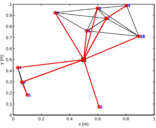
We evaluate the performance of the proposed privacy– preserving scheme via Monte Carlo simulation. The N SMs are uniformly located in the a × a square area and the aggregator is located at the center of the square at a2,a2
. Figure 3 shows an example of reporting tree with 10 SMs with a= 1 anddo= 12. The reporting tree is built based on
the procedure of the initialization phase, which is provided in Section III-(a). In this simulation, as the measurement data of SMs, s= [s1· · ·sN], we use a high-resolution data set of
electrical power demand in dwellings in the East Midlands, UK [14], similar to [6].
For the performance metrics, we show the MSE of the ag-gregated data at the aggregator,eP
S, which is given in (14), and MSEs of the data of the target SM at the colluding eavesdrop-pers (NE= 3) with compromised SMs,eP,Cχ , and non-colluding
eavesdropper (NE= 1),eP,Nχ . The number of the compromised
SMs are NC = 0,2,6. Therefore, the performance is good if
eP
S is small bute P,C
χ andeP,Nχ are large. We also plot the MSEs
at the aggregator, eB
S, and at the colluding eavesdroppers,e B χ,
of the perturbation method as the benchmark scheme [4], [8], [11]. Since we do not consider cryptographic operation with highly computational complexity, the benchmark scheme only includes the perturbation part of the existing schemes [4], [8], [11]. In the benchmark scheme, each SM adds a random noise to the measured data and transmits it to the aggregator. Hence,
0 0.2 0.4 0.6 0.8 1
0 0.1 0.2 0.3 0.4 0.5 0.6 0.7 0.8 0.9 1
10
1
2 3
4
5 6
7 8
9
10
x (m)
y (m)
Fig. 3. An example of a network with 10 SMs. The red segments represent branches of the reporting tree with the root as the aggregator. The red and black segments represent direct wireless channels between any two SMs/aggregator.
the transmit signal ofi-th SM is given by
¨
ui=si+ ¨zi+
X
j∈Di
¨
uj, (25)
wherez¨i ∈ CN(0, σ2B) is the added random noise at the i-th SM and the third term in (25) includes the received signals from descendant nodes of Si. Even though only the
pertur-bation part of the existing scheme is used, the comparison in the simulation is still valuable since in many scenarios, the infrastructure for cryptographic operation is not available or too expensive in terms of computation.
In Fig. 4, we plot the MSEs of the proposed and bench-mark schemes according to transmit SNR when N = 10,
a = 1m, and do = 12m. For the comparison, we set the
added noise power of perturbation scheme σ2B = -16dBm such that eBχ ≈ ePχ,N in order to compare the two schemes
in the other metric, eP
S and eBS. As shown in Fig. 4, MSE at the aggregator of the proposed scheme, ePS, is significantly lower than that of the perturbation-only scheme, eBS. In the perturbation scheme, the aggregator cannot reliably estimate
sS due to the jamming signals (the added noises). The noise at any receiver is strongly masked by these jamming signals thus the MSE does not decrease with SNR. Moreover, if the NC increases, the MSE at the colluding eavesdroppers of the proposed scheme,eP,C
χ , decreases since the eavesdroppers
obtain more information about the related channels and mea-surements from the compromised nodes and thus, they can cancel more jamming signals. However, as shown in Fig. 4, when the number of the compromised SMs is large such as
NC= 6,ePχ,C is still much higher than ePS.
In Fig. 5, the MSEs are plotted according to the edge of the square area, a, when transmit SNR is 20dB andN = 10. The MSE of all cases increases with a or at least does not decrease. Since the same number of SMs are uniformly located in a larger area, the communication distances between SMs become larger and hence, the MSEs increase.
10 12 14 16 18 20 22 24 26 28 30 10−5
10−4 10−3 10−2 10−1 100 101
SNR, dB Mean squared error eBχ
eP,Nχ
eP,C
χ, nC = 0
eP,Cχ, nC = 2
eP,Cχ, nC = 6
eB S
ePS
Fig. 4. The MSE of the proposed and the perturbation-only schemes when estimatingsχandsSwitha= 1m and varied SNR.
1 1.5 2 2.5 3 3.5 4 10−4
10−3 10−2 10−1 100 101
Area edge, m
Mean squared error
nC = 0 n
C = 2 n
C = 6 eBχ
eP S eP,Nχ
eB S
eP,C χ
Fig. 5. The MSE of the proposed and the perturbation-only schemes when estimatingsχandsSwith SNR= 20dB,N= 10, and varieda.
a = 1m. We can see that for the proposed scheme, the MSE of sS at the aggregator increases rapidly with the number of SMs because the accumulated noise at the aggregator increases with the number of hops from the SMs to the aggregator. On the other hand, MSE at the colluding eavesdroppers increases slowly since the accumulated noise at the eavesdroppers is only related to the number of SMs on the same branch with the target SM, Sχ, rather than all SMs.
VI. CONCLUSION
We propose a novel privacy–preserving scheme in smart– grid data aggregation based on the information of the physical channels. Instead of using cryptographic operations, each SM simply uses its linked channels as the jamming signals on its measurement. Since the jamming signals are designed to be completely cancelled at the aggregator, it is difficult for the eavesdroppers to decode the measurement of SM while the aggregator can estimate the total electrical consumption in the area. The simulation results show that the mean squared error (MSE) of the individual measurements at the eavesdropper is very high while MSE of the total measurement at the aggregator is very low, which is significantly lower than that of the traditional perturbation–only scheme.
8 10 12 14 16 18 20 22 10−4
10−3 10−2 10−1 100 101 102
Number of SMs (N)
Mean squared error
eBχ eP,Nχ eP,Cχ , n
C = 0 eP,Cχ , n
C = 2 eP,Cχ , n
C = 6 eB
S eP S
Fig. 6. The MSE of the proposed and the perturbation-only schemes when estimatingsχandsSwith SNR= 20dB,a= 1m and variedN.
ACKNOWLEDGEMENT
This work was partly supported by the Temasek Research Fellowship and the A*STAR SERC Grant 1224104048.
REFERENCES
[1] C.-I. Fan, S.-Y. Huang, and Y.-L. Lai, “Privacy-enhanced data aggre-gation scheme against internal attackers in smart grid,” IEEE Trans. Industrial Info., vol. 10, no. 1, pp. 666–675, Feb. 2014.
[2] S. Roy, M. Conti, S. Setia, and S. Jajodia, “Secure data aggregation in wireless sensor networks,” IEEE Trans. Info. Foren. and Sec., vol. 7, no. 3, pp. 1040–1052, Jun. 2012.
[3] Y. Yan, Y. Qian, and H. Sharif, “A secure data aggregation and dispatch scheme for home area networks in smart grid,” inIEEE Global Telecom. Conf. (GLOBECOM), Dec. 2011, pp. 1–6.
[4] W. Jia, H. Zhu, Z. Cao, X. Dong, and C. Xiao, “Human-factor-aware privacy-preserving aggregation in smart grid,”IEEE Systems J., vol. 8, no. 2, pp. 598–607, Jun. 2014.
[5] Z. Erkin, J. R. Troncoso-pastoriza, R. L. Lagendijk, and F. Perez-Gonzalez, “Privacy-preserving data aggregation in smart metering sys-tems: an overview,”IEEE Signal Processing Magazine, vol. 30, no. 2, pp. 75–86, Mar. 2013.
[6] H. Bao and R. Lu, “A new differentially private data aggregation with fault tolerance for smart grid communications,”IEEE Internet of Things J., vol. 2, no. 3, pp. 248–258, June 2015.
[7] C. Rottondi, G. Verticale, and C. Krauss, “Distributed privacy-preserving aggregation of metering data in smart grids,”IEEE J. on Sel. Areas in Comm., vol. 31, no. 7, pp. 1342–1354, Jul. 2013.
[8] M. Savi, C. Rottondi, and G. Verticale, “Evaluation of the precision-privacy tradeoff of data perturbation for smart metering,”IEEE Trans. Smart Grid, vol. 6, no. 5, pp. 2409–2416, Sep. 2015.
[9] J. Choi, J. Bang, L. Kim, M. Ahn, and T. Kwon, “Location-based key management strong against insider threats in wireless sensor networks,”
IEEE Sys J., vol. PP, no. 99, pp. 1–9, May 2015.
[10] L. Chen, R. Lu, and Z. Cao, “PDAFT: A privacy-preserving data aggregation scheme with fault tolerance for smart grid communications,”
Springer Peer-to-Peer Networking and App., vol. 8, no. 2, pp. 1122– 1132, Jun. 2015.
[11] G. Acs and C. Castelluccia, “I have a DREAM! (differentially private smart metering),” inLNCS, 2011, p. 110.
[12] F. Ye, Y. Qian, and R. Q. Hu, “A security protocol for advanced metering infrastructure in smart grid,” in IEEE Global Comm. Conf. (GLOBECOM), Dec 2014, pp. 649–654.
[13] E. S. Rigas, S. D. Ramchurn, and N. Bassiliades, “Managing electric vehicles in the smart grid using artificial intelligence: A survey,”IEEE Trans. on Intelligent Transport. Systems, vol. 16, no. 4, pp. 1619–1635, Aug 2015.