Utility of Pelvic Computed Tomography
Angiography Prior to Prostatic Artery
Embolization
Ari J. Isaacson, MD
1Lauren M. B. Burke, MD
11Department of Radiology, University of North Carolina, Chapel Hill,
North Carolina
Semin Intervent Radiol 2016;33:224–230
Address for correspondence Ari J. Isaacson, MD, Department of Radiology, University of North Carolina, 2016 Old Clinic Building, CB# 7510, Chapel Hill, NC 27599 (e-mail: [email protected]).
Objectives: Upon completion of this article, the reader will be able to discuss the utility of pelvic CTA in patients prior to prostatic artery embolization.
Accreditation: This activity has been planned and imple-mented in accordance with the Essential Areas and Policies of the Accreditation Council for Continuing Medical Education (ACCME) through the joint providership of Tufts University School of Medicine (TUSM) and Thieme Medical Publishers, New York. TUSM is accredited by the ACCME to provide continuing medical education for physicians.
Credit: Tufts University School of Medicine designates this journal-based CME activity for a maximum of1 AMA PRA Category 1 Credit™. Physicians should claim only the credit commensurate with the extent of their participation in the activity.
Achieving technical success during prostatic artery embolization (PAE) can be challenging for two reasons:
first, the multiple overlapping branches of the internal iliac artery onfluoroscopy can make identification of the pros-tatic arteries (PAs) difficult and, second, the small diameter of the target vessels and tortuosity of the arteries from
which they arise can hinder catheter placement. Preproce-dural pelvic computed tomography angiography (CTA) can be used to overcome these challenges by allowing for anatomic evaluation and technical planning prior to the procedure and anatomic guidance during the procedure. Additionally, CTA can be used to determine the baseline prostate volume.
Computed Tomography Angiography
Technique
Imaging is performed on a 64-slice scanner (Somatom Sensation 64; Siemens Medical Solutions, Munich, Germany). If the patient has not taken a phosphodiesterase inhibitor in the past 48 hours, two sprays of sublingual nitroglycerin (800 µg; Wilshire Pharmaceuticals, Atlanta, GA) are administered 2 minutes prior to imaging to dilate the PAs for improved visualization. A region of interest (ROI) is identified in the inferior abdominal aorta just above the bifurcation. Care is taken to avoid calcification in the ROI. Depending on the gauge of the intravenous catheter, 150 mL of iohexol (Omnipaque 350; GE Healthcare,
Keywords
►
prostatic artery
embolization
►
computed
tomography
angiography
►
interventional
radiology
Abstract
Pelvic computed tomography angiography (CTA) prior to prostatic artery embolization
is a beneficial tool for preprocedural planning to increase the likelihood of success during
what can be a challenging procedure. Additionally, the same CTA images can be used for
calculating the baseline prostate volume as well as for intraprocedural anatomic
guidance, adding to the value of the scan. This article discusses the technique used
for pelvic CTA and its role in preprocedural assessment of the pelvic vasculature prior to
prostatic artery embolization.
Issue Theme Men’s Health; Guest Editor, Charles Burke, MD
Copyright © 2016 by Thieme Medical Publishers, Inc., 333 Seventh Avenue, New York, NY 10001, USA.
Tel: +1(212) 584-4662.
DOI http://dx.doi.org/ 10.1055/s-0036-1586150. ISSN 0739-9529.
Waukesha, WI) is injected at 4 to 6 mL/s. Imaging is initiated when the ROI reaches a threshold of 300 Hounsfield units (HUs). Occasionally, the HUs plateau before reaching 300 and initiation of scanning is triggered manually by the technologist. Imaging parameters are as follows: 0.6 mm collimator with reconstructions at 2 mm, pitch 0.9, 0.33-second gantry rotation period, 120 kV, and 180 reference mA with automated modulation along the z-axis based on body mass (CARE Dose 4D, Siemens Medical Solutions). A 2-minute delayed sequence is obtained with similar parameters. Axial images are reconstructed in 2-mm slices and coronal and sagittal maximum intensity projection (MIP) reconstructions are also created from the arterial phase images. Axial images of 1.2 mm overlapping are then imported into postacquisition software (iNtution; TeraRecon, Foster City, CA) for three-dimensional (3D) volume rendering and prostate volume calculation via segmentation.
Evaluation of the Prostatic Arteries
The PAs can arise from any branch of the anterior division of the internal iliac artery and are not necessarily symmetric on both sides of the pelvis.1–3In addition, there are rare occasions when the prostate is supplied by an obturator artery with an aberrant origin from either the inferior epigastric artery or common femoral artery, which would not be seen on an internal iliac artery angiogram.4This variability adds to the difficulty of PA catheterization and makes evaluation of the arterial anatomy on preprocedural CTA important for techni-cal success during PAE.
Most commonly, there are one or two PAs on each side. The arterial supply to the central portion of the prostate that is most affected by benign prostatic hyperplasia (BPH) is called the anterior/lateral prostatic artery (ALPA) because of the quadrant in which it inserts into the prostate on axial imag-ing. There is also a posterior/lateral prostatic artery (PLPA) that most commonly arises from the internal pudendal artery and supplies the prostatic capsule as well as the most inferior portion of the gland. Occasionally, both the ALPA and PLPA arise from a common trunk, in which case the diameter of the artery is larger, measuring approximately 1.9 mm as opposed to 1.3 mm.1With good technique, both the ALPA and PLPA will be opacified and be seen coursing into the expected quad-rants of the prostate on axial CTA images. Both vessels can then be followed back to their origins. If there is uncertainty based on the axial images, coronal MIP images are often helpful for clarification (►Fig. 1).
Preprocedural Planning
Once the PAs have been identified on axial images, creating volume-rendered 3D images with postacquisition software can be useful to determine the optimal obliquities for visuali-zation withfluoroscopy. The 3D images can be manipulated until the origins of the target arteries are perpendicular to the arteries from which they arise. These images and the
obliqui-orientation during the PAE procedure. The success of this technique, however, is dependent on adequate opacification of the PAs on CTA.
There are several factors that can make PA catheteriza-tion more technically challenging. Some anatomic confi g-urations present more of a challenge than others, such as when the ALPA originates from the anterior division of the internal iliac artery in a shared trunk with branches
cours-Fig. 1 (a) Axial maximum intensity projection computed tomography angiography (MIP CTA) image demonstrating the anterior/lateral prostatic arteries (white arrows) and the posterior/lateral prostatic arteries (black arrows) coursing along the capsule and inserting into their respective quadrants. (b) Coronal MIP CTA image from the same patient, clearly demonstrating the origin (white circle) of the common trunk of the left prostatic arteries (white arrows) arising from the left internal pudendal artery.
of successive acute angles through which a guidewire must pass, catheterization may require additional time and/or different guidewires. Second, atherosclerotic plaques can completely or partially obstruct the PA ostium, requiring additional maneuvering or even recanalization.5 Third, tortuous common or internal iliac arteries can limit
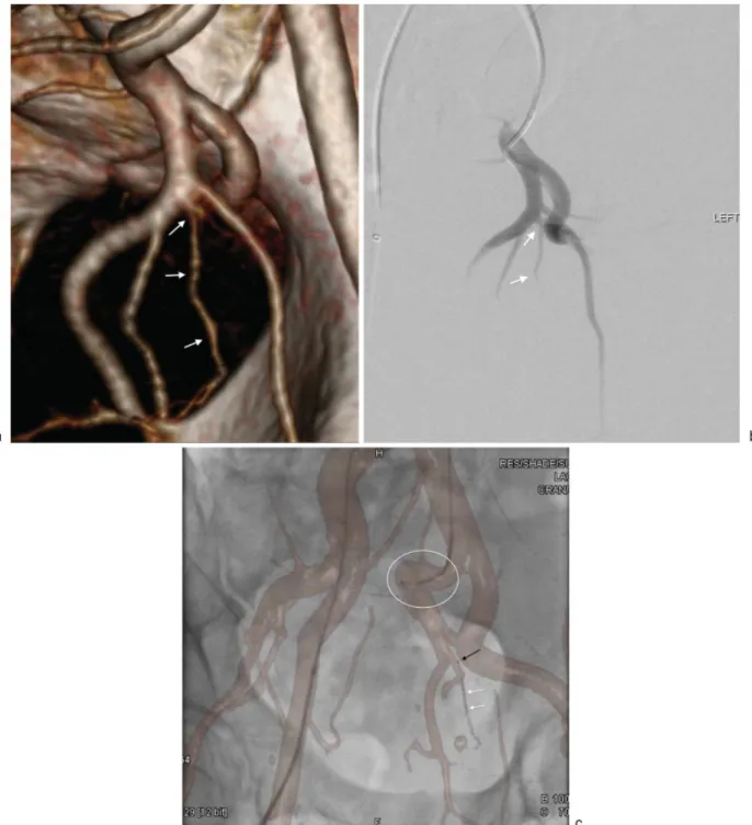
cathe-ter maneuverability. If these conditions are present, it is advantageous to know prior to the procedure to select the catheters and guidewires that will provide the best chance of success, as well as to give the patient a more accurate estimate of the duration and probability of success of the PAE (►Fig. 2).
Fig. 2 (a) Left anterior oblique maximum intensity projection computed tomography angiography (MIP CTA) image demonstrating an anatomic configuration in which prostatic artery catheterization can potentially be difficult. The left anterior/lateral prostatic artery (white arrows) can be seen coursing inferiorly from a common trunk with branches to the bladder (white arrowheads) and the seminal vesicle (black arrows). The difficulty arises because of the angles in which the guidewire has to traverse tofirst engage the common trunk from the anterior division and then course immediately inferiorly to select the anterior/lateral prostatic artery. (b) Right anterior oblique MIP CTA image demonstrating the right anterior/lateral prostatic artery (white arrows) arising from the origin of the anterior division of the right internal iliac artery. A calcified plaque (black arrow) can be seen partially obscuring the ostium of the anterior/lateral prostatic artery. (c) Left anterior oblique 3D volume-rendered CTA image demonstrating an aortic aneurysm (white circle) just proximal to the bifurcation and tortuosity of the right external iliac artery (white arrows). These factors were considered during preprocedural planning and a left common femoral artery access was used for this case.
Evaluation of the common femoral and the external iliac arteries is also helpful, as it may reveal stenoses, aneurysms, or tortuosity that would make traversal difficult. In this circumstance, one common femoral artery may be more favorable for access than the other. Furthermore, if both sides present challenges, a transradial approach can be considered.6
Finally, it has been shown that the PAs commonly anasto-mose with arterial branches that supply other organs, such as the bladder, rectum, and penis, presenting the potential for complications due to nontarget embolization.1These anasto-moses can commonly be seen on preprocedural CTA. When identified, preprocedural preparation can be made for tech-niques to prevent nontarget embolization such as selective coil or Gelfoam (Pfizer, New York, NY) embolization of the nontarget branch or proximal embolization with a larger particle (►Fig. 3).
Intra-procedural Guidance
Because of the numerous branch arteries that arise from the internal iliac artery, having a reference image to help with orientation during angiography can be beneficial,
espe-demonstrating optimal visualization of the PA origins described earlier can be present on a reference monitor adjacent to the fluoroscopy display. This allows for com-parison with the digital subtraction angiography (DSA) as it is acquired. A second method of guidance is fusion of the CTA with either a cone beam CT (CBCT) or orthogonal
fluoroscopic images obtained just prior to beginning the procedure. Overlying the bones of the pelvis and spine on both datasets results in accurate registration of the arteries during livefluoroscopy. Software available from multiple vendors allows for registration to be maintained during table andfluoroscope movement and changes in magnifi -cation, resulting in a dynamic arterial roadmap. If the PAs are well opacified on the preprocedural CTA, using this technique lessens the reliance on DSA for guidance during PA catheterization. However, DSA is still recommended before embolization to determine optimal catheter place-ment to avoid nontarget embolization and to identify any shunts to nontarget organs that were not identified on preprocedural CTA (►Fig. 4).
Prostate Volume
Determining the baseline prostate volume before PAE is important for postprocedural comparison. Although the degree of volumetric reduction does not correlate well with symptomatic improvement,7 observing no or very little reduction along with the absence of symptomatic improvement suggests inadequate embolization. The prostatic volume can be calculated on CTA by inputting diameter measurements into one of several formulas or by using autosegmentation software after manual or automat-ic demarcation of the prostatautomat-ic margins on successive axial slices. The most commonly used formula is the ellipsoid formula, which is as follows: anterior-posterior diameter
cranial-caudal diametertransverse diameterΠ/6. However, it should be noted that this formula underesti-mates the prostate volume in larger prostates, as is seen in advanced stages of BPH.8 The limitation of measuring prostate volume on CT is that it can be difficult to differen-tiate the base of the prostate from the bladder wall and apex of the prostate from the penile bulb, making measurements on ultrasound or magnetic resonance imaging more accu-rate.9 At our institution, we attempt to minimize this limitation by measuring the prostate volume on a delayed CTA sequence with improved contrast resolution between adjacent organs and visibility of the tissue planes (►Fig. 5).
Conclusion
PAE is emerging as an effective, safe, and minimally invasive therapy for BPH. However, the procedural difficulty that results from the pelvic arterial anatomy sets PAE apart from other interventional radiology procedures. Preprocedural CTA provides important information that, when used in preparation for PAE as well during the procedure for
guid-Fig. 3 Coronal maximum intensity projection computed tomography angiography (MIP CTA) image demonstrating the left anterior/lateral prostatic artery (white arrows) arising from an accessory pudendal artery (black arrows) and coursing into the prostate (white circle). The accessory pudendal artery can be seen anastomosing distally with the left internal pudendal artery (black arrowheads).
Fig. 4 (a) Right anterior oblique 3D volume-rendered CTA image demonstrating the optimal obliquity for visualizing the origin of the left anterior/lateral prostatic artery (white arrows). This image is displayed on a monitor in thefluoroscopy suite during prostatic artery embolization for comparison to angiography. (b) Digital subtraction angiography (DSA) image of the same patient using the same obliquity from the CTA image demonstrating a similar configuration of arteries. Using the CTA image for comparison eliminates any confusion about which is the anterior/lateral prostatic artery (white arrows). (c) Right anterior obliquefluoroscopic image with 3D volume-rendered CTA image overlaid for guidance. The 5F catheter can be seen with the tip in the left internal iliac artery (white circle). There is a coaxial microcatheter with the tip in the anterior division (black arrow) and a guidewire advanced into the anterior/lateral prostatic artery (white arrows). Using this dynamic overlay software limits the need for DSA images for guidance.
Fig. 5 (a) Axial, coronal, sagittal, and 3D volume-rendered CTA images from a delayed sequence demonstrating demarcation of the prostate after volume calculation using segmentation. (b) Sagittal arterial phase CTA image demonstrating similar densities of the prostate and the inferior bladder wall (white circle) making differentiation during volume measurement difficult. (c) Sagittal, delayed phase CTA image from the same patient demonstrating increased contrast resolution between the prostate and inferior bladder wall (white circle).
same imaging can be used to calculate the baseline prostate volume.
References
1 Bilhim T, Pisco JM, Rio Tinto H, et al. Prostatic arterial supply: anatomic and imaging findings relevant for selective arterial embolization. J Vasc Interv Radiol 2012;23(11):1403–1415
2 Clegg EJ. The arterial supply of the human prostate and seminal vesicles. J Anat 1955;89(2):209–216
3 Zhang G, Wang M, Duan F, et al. Radiologicalfindings of prostatic arterial anatomy for prostatic arterial embolization: preliminary study in 55 Chinese patients with benign prostatic hyperplasia. PLoS ONE 2015;10(7):e0132678
4 Bilhim T, Pisco J, Pinheiro LC, Rio Tinto H, Fernandes L, Pereira JA. The role of accessory obturator arteries in prostatic arterial embolization. J Vasc Interv Radiol 2014;25(6):875–879
5 Bagla S, Smirniotopolous JB, Vadlamudi V. Crossing a prostatic artery chronic total occlusion to perform prostatic arterial embo-lization. J Vasc Interv Radiol 2016;27(2):295–297
6 Isaacson AJ, Fischman AM, Burke CT. Technical feasibility of prostatic artery embolization from a transradial approach. AJR Am J Roentgenol 2016;206(2):442–444
7 Pisco JM, Rio Tinto H, Campos Pinheiro L, et al. Embolisation of prostatic arteries as treatment of moderate to severe lower urinary symptoms (LUTS) secondary to benign hyperplasia: results of short- and mid-term follow-up. Eur Radiol 2013; 23(9):2561–2572
8 Matthews GJ, Motta J, Fracehia JA. The accuracy of transrectal ultrasound prostate volume estimation: clinical correlations. J Clin Ultrasound 1996;24(9):501–505
9 Roach M III, Faillace-Akazawa P, Malfatti C, Holland J, Hricak H. Prostate volumes defined by magnetic resonance imaging and computerized tomographic scans for three-dimensional confor-mal radiotherapy. Int J Radiat Oncol Biol Phys 1996;35(5): 1011–1018
Fig. 5 (Continued)