Available online throug
ISSN 2229 – 5046
SORET AND DUFOUR EFFECTS ON CONVECTIVE HEAT AND MASS TRANSFER FLOW
OF MICROPOLAR FLUID IN A CIRCULAR ANNULUS
P. SOMASEKHARA REDDY*
1, Prof. D. R. V. PRASADA RAO (Rtd)
21
Research Scholar, Department of Mathematics,
Rayalaseema University, Kurnool, (A.P.), India.
2
Department of Mathematics,
S. K. University, Anantapuramu – 515 003, (A.P.), India.
(Received On: 25-12-17; Revised & Accepted On: 16-01-18)
ABSTRACT
I
n this paper, we make an attempt to investigate combined influence of magnetic field and dissipation on connective heat and mass transfer flow of a viscous chemically reacting fluid through a porous medium in the concentric cylindrical annulus with inner cylinder maintained at constant temperature and concentration on the other cylinder maintained constant heat flux. The equations governing the flow, heat, Mass and micro rotation are solved by employing Galerkin finite element analysis with quadratic approximation functions. The temperature, concentration and micro concentration distributions are analyzed for different values of Sr/Du, γ, Ec, ∆, λ and A. The rate of heat and mass transfer and couple stress are numerically evaluated for different variations of the governing parameters.Keywords: Soret and Dufour effects, heat and mass transfer, Circular annulus, micropolar fluid.
1. INTRODUCTION
An enclosed cylindrical annular cavity formed by three vertical, concentric cylinders, containing a fluid through which heat is transferred by natural convection, is a simplified representation of a number of practical and experimental situations. Also, the annulus represents a common geometry employed in a variety of heat transfer systems ranging from simple heat exchangers to the most complicated nuclear reactors. Since, the flow and heat transfer in a cylindrical annular configuration contains all the essential physics that are common to all confined natural convective flows, a complete understanding of the flow in such geometry is very essential. In addition, from a computational stand point, the annular configuration allows investigation of a wide range of geometrical effects. Convection is an important phenomenon in the crystal growth techniques as it can account for heat transfer in the liquid phase and can change the material properties.
The theory of micropolar fluids initiated by Eringen [5] exhibits some microscopic effects arising from the local structure and micro motion of the fluid elements. Further, they can sustain couple stress and include classical Newtonian fluid as a special case. The model of micropolar fluid represents fluids consisting of rigid randomly oriented (or sphenical) particles suspended in a viscous medium where the deformation of the particles is ignored. The fluid containing certain additives, some polymeric fluids and animal blood are examples of micropolar fluids. The mathematical theory of equations of micropolar fluids and application of these fluids in the theory of lubrication and porous media is presented by Lukaszewics [12]. Agarwal and Dhanpal [1] obtained numerical solution of micropolar fluid flow and heat transfer between two co-axial porous circular cylinders.Verma and Singh [27] have analyzed the behaviour of parametric fluid flow in a porous annulus in the presence of external magnetic field acting parallel to the common axis of the long co axial porous cylindrical tubes. Panja et.al [19] studied the flow of electrically conducting Reiner – Rivlin fluid between two non-conducting co axial circular cylinders with porous walls in the presence of uniform magnetic field. Shivashankar et.al [23] have obtained numerical solution to the MHD flow of micropolar fluid between two concentric porous cylinders; Murthy et.al [14] have considered study flow of micropolar fluid through a circular pipe under a transverse magnetic field with constant suction and injection.
Corresponding Author: P. Somasekhara Reddy*
1,
© 2018, IJMA. All Rights Reserved 80
Gebhart [10], Gebhart and Mollendorf [11] have shown that viscous dissipation heat in the natural convective flow is important when the flow field is of extreme size at extremely low temperature or in high gravitational field. On the other hand Barletta [3] have pointed out that relevant effects of viscous dissipation on the temperature profiles and on Nusselt number my occur in the fully developed forced convection in tubes. In view of this several authors notably Soundalgekar and Pop [26]. Soundalgekar et.al [24], Barletta and Zandhicn [4], Sreevani [25], El-Hakein [6] and Barletta [3] have studied the effect of viscous dissipation on the convective flows past an infinite vertical plate and through vertical channels and ducts. The effect of viscous dissipation on natural convection has been studied for some different cases including the natural convection from horizontal cylinder embedded in a porous media by Fand and Brucker [7], Giampietrao Fabbri [9] and Sreevani [25]. They reported that the viscous dissipation may not be neglected in all cases of natural convection from horizontal cylinders and further that the inclusion of a viscous dissipation term in a porous medium may lead to more accurate correlation equations, the effect of viscous dissipation has been studied by Nakayama and Pop [15] for steady free convection boundary layer over a non-isothermal body of arbitrary shape embedded in porous media. They used the integral method to show that the viscous dissipation results in lowering the level of the heat transfer rate from the body. This observation has been pointed also by Murthy and Singh [13] for the natural connection flow along an isothermal wall embedded in a porous medium. They concluded that that the effect of viscous dissipation increases as we move from Non-Darcy regime to Darcy regime. Recently, Prasuna et.al (28) have analysed the effect of dissipation and Soret effect on convective heat and mass transfer flow through a porous medium in a concentric annulus.
2. FORMULATION OF THE PROBLEM
We consider the steady flow of an incompressible, viscous, electrically conducting micropolar fluid through a porous medium in an annulus region between the concentric porous cylinders r = a and r = b (b > a) under the influence of a
radial magnetic field 20
r
H
.
The fluid is injected through the inner cylinder with radial velocity ua and flows outward through the outer cylinder with a radial velocity ub. We also take the viscous, Darcy and Ohmic dissipation into account
The velocity and micro rotation are taken in the form vr = u(r), vθ = v = 0, vz = w(r)
ωr = 0, ωθ = ω(r), ωz = 0 (1)
The equations governing the flow and heat and mass transfer eqn.(1)
0
=
+
∂
∂
r
u
r
u
2
2 2
1
1
(
)
u
p
u
u
u
u
k
u
r
r
r
r r
r
k
µ
ρ
∂
= −
∂
+
µ
+
∂
+
∂
−
−
∂
∂
∂
∂
(2)2
2
1
1
(
)
(
)
w
p
w
w
w
u
k
g
w k
r
r
z
r
r r
k
r
µ
ρ
∂
= −
∂
+
µ
+
∂
+
∂
−
ρ
−
−
∂
ω
∂
∂
∂
∂
∂
(3)ω
ω
ω
ω
ρ
k
r
w
k
r
N
r
r
r
r
r
ju
21
22
2
−
∂
∂
−
−
∂
∂
+
∂
∂
=
∂
∂
(4)
2 2
2 2
0 2 2
2 2 2 2
2 2
1
1
(2
)
2
1
1
+2
2
(
)
2
p f
m T
H e
s
T
T
T
u
w
C w
k
k
z
r
r r
r
r
r
D K
w
C
C
k
r
Q T
T
r
r
r
r
r
C
r
r r
µ
ρ
µ
β
ω
ω
ω
ω
ω
∂
=
∂
+
∂
+
+
∂
+
+
∂
∂
∂
∂
∂
∂
∂
∂
∂
∂
∂
+
−
+
+
−
−
+
+
∂
∂
∂
∂
∂
(5)
2 2
2 2
1
m T1
m
m
D K
C
C
C
T
T
w
D
C
z
r
r r
γ
T
r
r r
∂
=
∂
+
∂
−
′
+
∂
+
∂
∂
∂
∂
∂
∂
(6))
(
)
(
o o oo
o
=
−
T
−
T
−
C
−
C
−
ρ
βρ
β
•ρ
ρ
(7)The boundary conditions are
u = ua, w = 0, ω = 0, T = T0 + A0 z, C = C0 + B0 z on r = a u = ub, w = 0, ω = 0, T = T1 + A0 z, C =C1 + B0 z on r = b
From the equation of continuity we obtain
ru = c, constant ⇒ru = aua = bub ⇒
r
au
u
=
aIn view of the boundary condition on temperature and concentration, we may write T = T0 + A0 (z) + θ(r), C =C0 + B0(z) + φ(r)
On introducing the non-dimensional variables r′, w′, θ′, p′ and N′ as
0 0 2 2 2 2 0
0
,
(
)
,
,
,
,
C
C
C
C
a
p
p
a
k
T
T
T
T
a
v
w
w
a
r
r
i i−
−
=
=
′
+
=
′
−
−
=
=
′
=
′
φ
µ
ρ
µ
ρ
ω
µ
ω
θ
The equations (2) – (4) reduces to (on dropping the dashes)
)
(
)
(
1
1
1
1 1 1 1 2 21
θ
φ
ω
π
r
r
r
N
G
w
D
w
r
M
w
r
S
w
rr r∂
∂
∆
−
+
−
+
+
−
=
∆
+
−
+
−(
)
dr
dw
r
A
A
r
r
SA
r rr2
1
1
1
1 2∆
=
−
∆
−
−
+
ω
ω
ω
(8)2 2 2 4 2 2 1 4
1
(2
)
2
2
1
1
Pr(
)
2
r r
r T rr r rr r r
r
S
w
w
r
P N w
Du
EcP
r
r
A w
r
r
ω
θ
θ αθ
φ
φ
ω
ω
ω
+ ∆
+
+ ∆
+
=
+
−
+
+
+
∂
− ∆
+
+
∂
(9)1
1
c rr r rr r
Sc N w
ScSo
r
r
φ
φ γ ϕ
θ
θ
=
+
−
+
+
where 3 0 2(
i)
ga T
T
G
β
ν
−
=
(Grashof number),1 2 1
k
a
D
−=
(Darcy parameter)f p r
k
C
P
=
µ
(Prandtl number),2 2 0
(
)
p ia
Ec
C T
T v
=
−
(Eckert number)2
H
f p
Q a
k C
α
=
(Heat source parameter),S
au
aν
=
(Suction parameter) 0 0(
)
(
)
m T i
m i
D K C
C
So
T T
T
−
=
−
(Soret parameter),0
0
(
)
(
)
m T i
s i
D K T
T
Du
C C
C
−
=
−
(Dufour parameter)m
D
a
2γ
γ
=
′
(Chemical Reaction parameter),k
a
r
A
µ
µ
∆
=
=
2 (Micropolar parameters)1 1
1
,
1,
1,
1
1
1
D
G
b
D
G
r
a
− −∆
∆ =
=
=
=
+ ∆
+ ∆
+ ∆
The non-dimensional boundary conditions are
w = 0, θ = 1,
φ
=1 N = 0 on r = 1© 2018, IJMA. All Rights Reserved 82 3. METHOD OF SOLUTION
The finite element analysis with quadratic polynomial approximation functions is carried out along the radial distance across the circular cylindrical annulus. The behavior of the velocity, temperature and concentration profiles has been discussed computationally for different variations in governing parameters. The Gelarkin method has been adopted in the variation formulation in each element to obtain the global coupled matrices for the velocity, temperature and concentration in course of the finite element analysis. Choose an arbitrary element ek and let wk, θk, ∅k and Nk be the values of w, θ, ∅ and N in the element ek.
We define the error residuals as
1
1
(
)
1(
)
1
k k
k k k k k
w
d
dw
dw
E
r
r
r
D rw
Gr
N
dr
dr
dr
λ
ω
π
−θ
ϕ
=
−
+ ∆
+
−
−
+
+ ∆
(11)2 2
3
2 2
1
(2
)
((2
)
)
1
2
2
2
Pr
k kr t r r
k
dw
r
A
r
dr
d
d
E
r
P N w
EcP
dr
dr
dw
d
r
A
A
dr
dr
r
d
d
Du
r
dr
dr
θλ
θ
αθ
ω
ω
ω
ω
φ
+ ∆
+
+ ∆ +
+
=
−
−
+
∆
+
−
+
+
(12) k k k kC C r
d
d
d
d
E
r
ScN w
ScSo
r
dr
dr
dr
dr
φ
γφ
θ
=
−
−
+
(13)dr
dw
A
A
r
r
dr
d
Ar
dr
d
r
dr
d
E
k k k k k N∆
−
−
∆
−
−
=
ω
ω
ω
1
2
ω
(14)Where wk, θk, φk and
ω
k are values of w, θ, ∅ andω
in the arbitrary element ek. These are expressed as linear combinations in terms of respective local nodal values.k i k i i k k k k k k k
w
w
w
w
w
ψ
ψ
ψ
∑
ψ
=
=
+
+
=
3 1 3 3 2 2 1 1 k i k i i k k k k k kk
θ
ψ
θ
ψ
θ
ψ
θ
ψ
θ
∑
==
+
+
=
3 1 3 3 2 2 1 1 (15) 31 1 2 2 3 3 1
k k k k k k k k k
i i i
φ
φ ψ
φ ψ
φ ψ
φ ψ
=
=
+
+
=
∑
k i k i i k k k k k kk
ω
ψ
ω
ψ
ω
ψ
ω
ψ
ω
∑
==
+
+
=
3 1 3 3 2 2 1 1Where
ψ
1k,
ψ
2k,...
etc are Lagrange’s quadratic polynomials.Substuting eqn(15) in equations (11 – 14) and evaluating the resulting integral we get local stiffness matrices. These matrices are assembled into global matrix by using inter element continuity, equilibrium and boundary conditions. These global matrices are solved by iteration procedure. The iteration process is repeated until the convergence is obtained i.e. |ui+1-ui| < 10-6.
4. SHEAR STRESS, NUSSELT NUMBER, SHERWOOD NUMBER
The shear stress (τ) is evaluated using the formula
1, r S du dr
τ
= =
The rate of heat transfer (Nusselt number) is evaluated using the formula
, r S d Nu dr θ = −
The rate of mass transfer (Sherwood number) is evaluated using the formula
, r S
d
Sh
dr
φ
= −
The couple stress at the inner and outer cylinder are evaluated by *
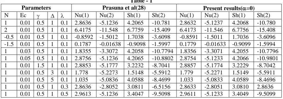
COMPARISON
In the absence of Heat sources (α=0) and Dufour effect (Du=0) the results are in good agreement with those of Prasuna
et.al (28)
Table - 1
Parameters Prasuna et al(28) Present results(α=0)
N Ec γ ∆ λ Nu(1) Nu(2) Sh(1) Sh(2) Nu(1) Nu(2) Sh(1) Sh(2)
1 0.01 0.5 1 0.1 2.8636 -5.1236 4.2065 -10.781 2.8632 -5.1237 4.2068 -10.780
2 0.01 0.5 1 0.1 6.4175 -11.548 6.7759 -15.409 6.4173 -11.546 6.7756 -15.408
-0.5 0.01 0.5 1 0.1 -0.8592 -1.5012 1.7038 -3.6098 -0.8591 -1.5011 1.7036 -3.6096 -1.5 0.01 0.5 1 0.1 0.1787 -0.01638 -0.9098 -1.5997 0.1779 -0.01633 -0.9099 -1.5994
1 0.03 0.5 1 0.1 1.8355 -3.3072 4.2058 -10.7794 1.8356 -3.3071 4.2055 -10.7796
1 0.05 0.5 1 0.1 2.8756 -5.1236 4.2065 -10.8802 2.8754 -5.1233 4.2066 -10.9801
1 0.01 1.5 1 0.1 2.8853 -5.1777 3.2232 -8.7041 2.8857 -5.1774 3.2229 -8.7042
1 0.01 0.5 3 0.1 1.778 -5.2273 1.5148 -5.5912 1.779 -5.2271 1.5149 -5.5911
1 0.01 0.5 5 0.1 1.035 -5.0836 4.0588 -8.4699 1.033 -5.0833 4.0589 -8.4696
1 0.01 0.5 1 0.3 2.8636 -2.8052 3.0811 -6.5156 2.8633 -2.8051 3.0810 2.8636
1 0.01 0.5 1 0.5 2.9613 -5.1236 3.4047 -9.5098 2.9611 -5.1233 3.4049 -9.5099
5. RESULTS AND DISCUSSION
In this analysis we investigate the effect of thermo-diffusion, diffusion-thermo, dissipation, heat sources and chemical reaction on mixed convective heat and mass transfer flow of a micro polar fluid through a porous medium in circular annulus between the cylinders r=a and r=b which are maintained at constant temperature and concentration. The non-linear coupled equations governing the flow heat and mass transfer are solved by Galerkin finite element analysis with quadratic approximation functions. the effect of important parameters namely micro polar parameter Δ, the suction
Reynolds number λ and Dufour parameter Du has been studied for these functions and corresponding profiles.
Fig.1 shows the effect of Soret and Dufour effects on w. It can be seen from the graphs that increasing Soret parameter So( or decreasing Dufour parameter Du) smaller|w|. Fig.2 represents w with chemical reaction parameter γ. It is found that the magnitude of w reduces in degenerating/ generating chemical reaction cases. The effect of dissipation on w is exhibited in Fig.3. It is found that smaller the dissipative effect smaller the magnitude of w. From Fig.4 represents w with micropolar parameter (∆).It can be seen from the profiles that the axial velocity enhances with increase in ∆.in the entire flow region. Fig.5 represents w with suction parameter λ. It is found that |w| enhances with increase in λ.An increase in the micropolar parameter (A) increases the magnitude of w in the flow region (fig.6).
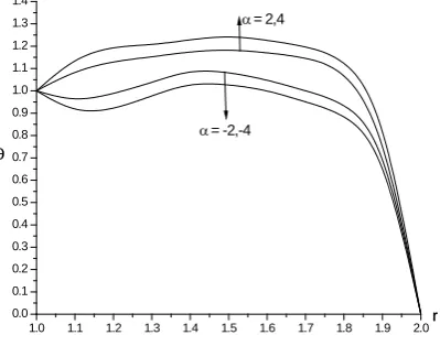
The non-dimensional temperature (θ) is exhibited in Figs. 7-13 for different parametric values. It is found that the non-dimensional temperature is always positive for all variations. This indicates the actual temperature is always greater than T0.. Higher the thermo-diffusion effects (or smaller the diffusion thermo effects) smaller the actual temperature in the flow region (fig.7). Fig.8 represents θ with heat source parameter α.We notice from the profiles that the actual temperature enhances with increase in the strength of the heat generating source and reduces with that of heat absorbing source. Fig.9 represents θ with chemical reaction parameter γ. It is found that the actual temperature enhances in the degenerating chemical reaction case and reduces in the generating case. The variation of θ with Eckert number Ec is shown in the Fig. 10. It is found that the actual temperature reduces with Ec in the entire flow region.Thus higher the dissipation lesser the actual temperature in the flow region..Fig.11 shows the variation θ with micropolar parameter
∆.Higher the values of ∆, lesser the actual temperature in the flow region. The variation of θ with λ is exhibited in Fig.12 it is found that the actual temperature experiences an enhancement with increase in suction parameter. Fig.13 exhibits θ with micropolar parameter A. It can be seen from the graphs that the actual temperature enhances with increase in A.
© 2018, IJMA. All Rights Reserved 84
The micro rotation (ω) is shown in Figs. 20-25 for different parametric values. Higher the thermo-diffusion effects(or smaller the diffusion-thermo effects) larger the magnitude of the angular velocity (fig.20). From fig.21 we notice that the angular velocity ω reduces in magnitude in both degenerating and generating chemical reaction cases. From fig.22 we find that higher the dissipation lesser the actual concentration in the flow region. An increase in micropolar parameter ∆ increases |ω| in the region (fig.23). An increase in suction parameter λ enhances |ω| in the flow region (fig.24). From fig.25 we find that |ω| enhances with increase in micropolar parameter A≤1 and reduces with higher A≥1.5.
The stress (τ) at the inner and outer cylinders is exhibited in Table-2 for different parametric values. The stress enhances at r=1 and r=2 with increase in strength of heat degenerating source while it reduces with that of heat absorbing source. An increase in micro rotation parameter A results in an enhancement in |τ| at r=2 and depreciates at r=1. With respect to viscosity ratio parameter Δ we find that |τ| enhances at r=1 and reduces at r=2 with increase in ∆. With reference to Eckert number Ec it can be seen that |τ| enhances with increase in Ec at r=1&2. The variation of τ with chemical reaction parameter γ shows that |τ| reduces in the degenerating chemical reaction case and enhance in the generating chemical reaction case. Higher the thermo-diffusivity (or smaller the diffusion-thermo effects) larger the stress at both the cylinders. An increase in suction parameter (λ) larger the stress at the cylinders.
The rate of heat transfer (Nusselt number) (Nu) at r=1 and r=2 is shown in Table-2 for different parametric values. An increase in suction parameter λ enhances |Nu| at both cylinders. The variation of Nu with micro rotation parameter A and viscosity ratio parameter Δ shows that |Nu| enhances with A and Δ at r=1 and while at r=2, it enhances at r=1 and reduces at r=2. The variation of Nu with Ec shows that higher the dissipative heat smaller |Nu|. Also |Nu| experiences an enhances at r=1 &2 with γ>0 and reduces with γ <0. Higher the thermo-diffusion effect( or smaller the diffusion-thermo effects) larger Nu at r=1 and smaller at r=2.Also Nu reduces with increase in Sc at r=1&2.
The rate of mass transfer (Sherwood number) at r=1 and 2 is exhibited in Table-2 for different parametric values. We find that
the rate of mass transfer enhances with λ and reduces with Ec at r=1 and 2.An increase in ∆ reduces Sh at r=1 and enhances at r=2 while it enhances with A at both cylinders. The variation of Sh with Schmidt number Sc shows that lesser the molecular permeability larger |Sh| at r=1 and 2. Higher the thermo-diffusivity smaller |Sh| at both the cylinders. With respect to γ we find that |Sh| enhances in degenerating and reduces in generating chemical reaction cases at both the cylinders. Decreasing Dufour parameter leads to an enhancement at the cylinders.
1.0 1.1 1.2 1.3 1.4 1.5 1.6 1.7 1.8 1.9 2.0
-0.4 -0.3 -0.2 -0.1
0.0 r
w
Sr = 2, 1.5, 1, 6 Du = 0.03,0.04,0.06,0.1
Fig. 1 : Variation of w with Sr & Du
γ=0.5, Ec=0.01, ∆=0.5, λ=0.3, A=0.5
1.0 1.1 1.2 1.3 1.4 1.5 1.6 1.7 1.8 1.9 2.0
-0.5 -0.4 -0.3 -0.2 -0.1 0.0
γ= 0.5,1.5,-0.5,-1.5
r W
Fig. 2 : Variation of w with γ
1.0 1.1 1.2 1.3 1.4 1.5 1.6 1.7 1.8 1.9 2.0
-0.4 -0.3 -0.2 -0.1
0.0W r
Ec = 0.01,0.03,0.05,0.07
Fig. 3 : Variation of w with Ec
Sr&Du=2/0.03, γ=0.5, ∆=0.5, λ=0.3, A=0.5
1.0 1.1 1.2 1.3 1.4 1.5 1.6 1.7 1.8 1.9 2.0
-0.6 -0.5 -0.4 -0.3 -0.2 -0.1
0.0 r
w
∆ = 0.5,1.5,1.5,2
Fig. 4 : Variation of w with ∆
Sr&Du=2/0.03,γ=0.5, Ec=0.01, λ=0.3, A=0.5
1.0 1.1 1.2 1.3 1.4 1.5 1.6 1.7 1.8 1.9 2.0
-0.6 -0.5 -0.4 -0.3 -0.2 -0.1 0.0
λ = 0.03,0.05,0.07,0.09
r
w
Fig. 5 : Variation of w with λ
Sr&Du=2/0.03,γ=0.5, Ec=0.01, ∆=0.5, A=0.5
1.0 1.2 1.4 1.6 1.8 2.0
-0.55 -0.50 -0.45 -0.40 -0.35 -0.30 -0.25 -0.20 -0.15 -0.10 -0.05 0.00
A = 0.5,1,1.5,2
r
w
Fig. 6 : Variation of w with A
Sr&Du=2/0.03,γ=0.5, Ec=0.01, ∆=0.5, λ=0.3
1.0 1.1 1.2 1.3 1.4 1.5 1.6 1.7 1.8 1.9 2.0 0.0
0.1 0.2 0.3 0.4 0.5 0.6 0.7 0.8 0.9 1.0 1.1 1.2 1.3 1.4
r
θ
Sr = 1.5, 2, 1, 6 Du = 0.04,0.03,0.06,0.1
Fig. 7: Variation of θ with Sr & Du
α=2, γ=0.5, Ec=0.01, ∆=0.5, λ=0.3, A=0.5
1.0 1.1 1.2 1.3 1.4 1.5 1.6 1.7 1.8 1.9 2.0 0.0
0.1 0.2 0.3 0.4 0.5 0.6 0.7 0.8 0.9 1.0 1.1 1.2 1.3 1.4
α = -2,-4
r
θ
α = 2,4
Fig. 8 : Variation of θ with α
© 2018, IJMA. All Rights Reserved 86
1.0 1.1 1.2 1.3 1.4 1.5 1.6 1.7 1.8 1.9 2.0 0.0
0.1 0.2 0.3 0.4 0.5 0.6 0.7 0.8 0.9 1.0 1.1 1.2 1.3 1.4
γ= 0.5,1.5
γ= -0.5,-1.5
r
θ
Fig. 9 : Variation of θ with γ
Sr&Du=2/0.03, α=2, Ec=0.01, ∆=0.5, λ=0.3, A=0.5
1.0 1.1 1.2 1.3 1.4 1.5 1.6 1.7 1.8 1.9 2.0 0.0
0.1 0.2 0.3 0.4 0.5 0.6 0.7 0.8 0.9 1.0 1.1 1.2 1.3 1.4
r
θ Ec = 0.01,0.03,0.05,0.07
Fig. 10 : Variation of θ with Ec
Sr&Du=2/0.03, α=2, γ=0.5, ∆=0.5, λ=0.3, A=0.5
1.0 1.1 1.2 1.3 1.4 1.5 1.6 1.7 1.8 1.9 2.0 0.0
0.1 0.2 0.3 0.4 0.5 0.6 0.7 0.8 0.9 1.0 1.1 1.2 1.3 1.4
r
θ ∆ = 0.5,2,1,1.5
Fig. 11 : Variation of θ with ∆
Sr&Du=2/0.03, α=2, γ=0.5, Ec=0.01, λ=0.3, A=0.5
1.0 1.1 1.2 1.3 1.4 1.5 1.6 1.7 1.8 1.9 2.0 0.0
0.1 0.2 0.3 0.4 0.5 0.6 0.7 0.8 0.9 1.0 1.1 1.2 1.3 1.4 1.5 1.6
λ = 0.03,0.05,0.07,0.09
r
θ
Fig. 12 : Variation of θ with λ
Sr&Du=2/0.03, α=2, γ=0.5, Ec=0.01, ∆=0.5, A=0.5
1.0 1.2 1.4 1.6 1.8 2.0 0.0
0.2 0.4 0.6 0.8 1.0 1.2 1.4
A = 0.5,1,1.5,2
r
θ
Fig. 13 : Variation of θ with A
Sr&Du=2/0.03, α=2, γ=0.5, Ec=0.01, ∆=0.5, λ=0.3
1.0 1.1 1.2 1.3 1.4 1.5 1.6 1.7 1.8 1.9 2.0 0.0
0.1 0.2 0.3 0.4 0.5 0.6 0.7 0.8 0.9 1.0
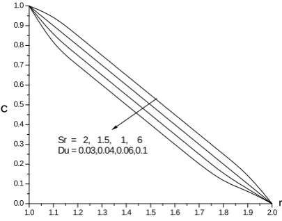
r C
Sr = 2, 1.5, 1, 6 Du = 0.03,0.04,0.06,0.1
Fig. 14 : Variation of C with Sr & Du
1.0 1.1 1.2 1.3 1.4 1.5 1.6 1.7 1.8 1.9 2.0 0.0
0.1 0.2 0.3 0.4 0.5 0.6 0.7 0.8 0.9 1.0
γ= 0.5,1.5
γ= -0.5,-1.5
r C
Fig. 15 : Variation of C with γ
Sr&Du=2/0.03, Ec=0.01, ∆=0.5, λ=0.3, A=0.5
1.0 1.1 1.2 1.3 1.4 1.5 1.6 1.7 1.8 1.9 2.0 0.0
0.1 0.2 0.3 0.4 0.5 0.6 0.7 0.8 0.9 1.0
r C
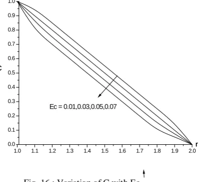
Ec = 0.01,0.03,0.05,0.07
Fig. 16 : Variation of C with Ec
Sr&Du=2/0.03, γ=0.5, ∆=0.5, λ=0.3, A=0.5
1.0 1.1 1.2 1.3 1.4 1.5 1.6 1.7 1.8 1.9 2.0 0.0
0.1 0.2 0.3 0.4 0.5 0.6 0.7 0.8 0.9 1.0
r C
∆ = 0.5,1.5,1.5,2
Fig. 17 : Variation of C with ∆
Sr&Du=2/0.03, γ=0.5, Ec=0.01, λ=0.3, A=0.5
1.0 1.1 1.2 1.3 1.4 1.5 1.6 1.7 1.8 1.9 2.0 0.0
0.1 0.2 0.3 0.4 0.5 0.6 0.7 0.8 0.9 1.0 1.1 1.2
λ = 0.03,0.05,0.07,0.09
r C
Fig. 18 : Variation of C with λ
Sr&Du=2/0.03, γ=0.5, Ec=0.01, ∆=0.5, A=0.5
1.0 1.2 1.4 1.6 1.8 2.0 0.0
0.1 0.2 0.3 0.4 0.5 0.6 0.7 0.8 0.9 1.0
A = 0.5,1,1.5,2
r C
Fig. 19 : Variation of C with A
Sr&Du=2/0.03, γ=0.5, Ec=0.01, ∆=0.5, λ=0.3
1.0 1.1 1.2 1.3 1.4 1.5 1.6 1.7 1.8 1.9 2.0 0.00
0.05 0.10 0.15 0.20
r
ω
Sr = 1.5, 2, 1, 6 Du = 0.04,0.03,0.06,0.1
Fig. 20 : Variation of ω with Sr & Du
© 2018, IJMA. All Rights Reserved 88
1.0 1.1 1.2 1.3 1.4 1.5 1.6 1.7 1.8 1.9 2.0 0.00
0.05 0.10 0.15 0.20 0.25
γ= 0.5,1.5
γ= -0.5,-1.5
r
ω
Fig. 21 : Variation of ω with γ
Sr&Du=2/0.03, Ec=0.01, ∆=0.5, λ=0.3, A=0.5
1.0 1.1 1.2 1.3 1.4 1.5 1.6 1.7 1.8 1.9 2.0 0.00
0.05 0.10 0.15 0.20 0.25
r
ω
Ec = 0.01,0.03,0.05,0.07
Fig. 22 : Variation of ω with Ec
Sr&Du=2/0.03,γ=0.5, ∆=0.5, λ=0.3, A=0.5
1.0 1.1 1.2 1.3 1.4 1.5 1.6 1.7 1.8 1.9 2.0 0.00
0.05 0.10 0.15 0.20
r
ω
∆ = 0.5,2,1,1.5
Fig. 23 : Variation of ω with ∆
Sr&Du=2/0.03, γ=0.5, Ec=0.01, λ=0.3, A=0.5
1.0 1.1 1.2 1.3 1.4 1.5 1.6 1.7 1.8 1.9 2.0 0.00
0.05 0.10 0.15 0.20
λ = 0.03,0.05,0.07,0.09
r
ω
Fig. 24 : Variation of ω with λ
Sr&Du=2/0.03, γ=0.5, Ec=0.01, ∆=0.5, A=0.5
1.0 1.1 1.2 1.3 1.4 1.5 1.6 1.7 1.8 1.9 2.0
-0.25 -0.20 -0.15 -0.10 -0.05 0.00 0.05 0.10 0.15 0.20 0.25 0.30 0.35
A = 1.5,2 A = 0.5,1
r
ω
Fig. 25 : Variation of ω with A
Table – 2: Skin friction(τ), Nusselt Number(Nu), Sherwood Number (Sh)
Sr/Du Ec γ ∆ λ A τ(1) τ(2) Nu(1) Nu(2) Sh(1) Sh(2)
1.5/0.04 0.01 0.5 0.5 0.03 0.5 -0.230781 0.195265 27.5746 -39.4183 24.3414 -2.76555 1.0/0.06 0.01 0.5 0.5 0.03 0.5 -0.207915 0.177720 27.5876 -39.4816 24.1194 -2.51809 0.6/0.1 0.01 0.5 0.5 0.03 0.5 -0.190827 0.163859 27.5833 -39.5266 23.9508 -2.32974 2.0/0.03 0.03 0.5 0.5 0.03 0.5 -0.224567 0.206754 28.6789 -39.6754 24.1245 -2.45677 2.0/0.03 0.05 0.5 0.5 0.03 0.5 -0.214357 0.196785 28.7865 -39.9876 24.0345 -2.24567 2.0/0.03 0.01 1.5 0.5 0.03 0.5 -0.222607 0.190357 27.5762 -39.4372 24.7299 -3.27399 2.0/0.03 0.01 -0.5 0.5 0.03 0.5 -0.356926 0.320449 27.5289 -38.9341 23.6319 -1.37049 2.0/0.03 0.01 -1.5 0.5 0.03 0.5 -0.370676 0.339257 27.5215 -38.8622 23.5043 -1.06722 2.0/0.03 0.01 0.5 1.0 0.03 0.5 -0.285995 0.199772 27.5617 -39.3091 24.5364 -2.99128 2.0/0.03 0.01 0.5 1.5 0.03 0.5 -0.292323 0.136248 27.5678 -39.4048 24.5352 -3.00435 2.0/0.03 0.01 0.5 0.5 0.05 0.5 -0.260393 0.219239 27.6277 -39.7609 24.5576 -3.00211 2.0/0.03 0.01 0.5 0.5 0.07 0.5 -0.268106 0.225663 27.6806 -40.1356 24.5709 -3.01302 2.0/0.03 0.01 0.5 0.5 0.03 1.0 -0.269625 0.222903 27.6043 -39.5454 24.5473 -2.99987 2.0/0.03 0.01 0.5 0.5 0.03 1.5 -0.262882 0.249704 27.6413 -39.3273 24.7648 -3.16548
6. CONCLUSIONS
Lesser the permeability of porous medium larger w, C, ω and θ in the flow region.
The velocity, temperature and concentration enhance, the microrotation reduces in the degenerating chemical reaction case and enhances in the generating case, the velocity enhances, temperature, concentration and microrotation reduce in the flow region.
An increasing suction parameter λ enhances w, θ, C and the angular velocity ω.
An increasing Eckert number Ec reduces the velocity, temperature, concentration and microrotation.
Higher the molecular diffusivity larger the velocity and concentration and smaller the temperature and microrotation in the flow region.
An increase in heat generating source parameter (α>0) enhances the temperature the temperature enhances in the flow region.
Higher the thermo-diffusion effect(or lesser the diffusion-thermo) smaller the velocity, temperature and enhances the concentration and microrotation in the flow region.
Higher the Lorentz force smaller the stress, and larger the rate of heat and mass transfer on the cylinders.
An increasing the micropolar parameter λ enhances |Nu|, |Sh| and |Cw| at both the cylinders.
Higher the dissipative heat smaller |τ|, |Sh|, and larger|Nu| at r=1 and 2
7. REFERENCES
1. Agarwal R.S. and Dhanpal C.: Numerical solution of micropolar fluid flow and heat transfer between two co-axial porous circular cylinders. Int. J. Eng. Sci., 26(11) pp. 1133-1142 (1988).
2. Barletta A., Magyari E., Lazzari S. and Pop I.: Closed from solutions for mixed convection with magneto hydro dynamic effect in a vertical porous annulus surrounding an electric cable. J. Heat Transfer, 131, 6, (2009).
3. Barletta A.: Int. J. Heat Mass Transfer, Vol. 40, pp. 15-26 (1997). 4. Barletta A.: Int. J. Heat Mass Transfer, Vol. 42, pp. 2243-2253, (1999).
5. Eringen A.C.: The theory of micropolar fluids – theory and application. Birkhauser, Bostan (1966). 6. El-Hakein M.A.: Int. Comns. Heat Mass Transfer, Vol. 27, pp. 581-590 (2000).
7. Fand R.M. and Brucker J.: Int. J. Heat and Mass Transfer. p. 723 (1986).
8. Grosan T., Revnic C., Pop I. and Ham D.B.: Magnetic field and internal heat generation effects on the free convection in a rectangular cavity filled with a porous medium. Int. J. Heat Mass Transfer, 52 (5-6). pp. 1525-1533 (2009).
9. GiampietroI Fabbri: Int. J. Heat and Mass Transfer, p. 3003 (2004). 10. Gebhart B.J.: Fluid Mech., Vol. 14, pp. 225-232, (1962).
11. Gebhart B. and Mollendorf J.: Fluid Mech., Vol. 38, pp. 107 (1969).
12. Lukaszewicz G.: Micropolar fluids, theory and applications, Birkhauser, Bostan (1999). 13. Murthy D.V.S. and Singh P.: Int. J. Heat and Mass Transfer, (1997).
14. Murthy J.V.R. and Bahali N.K.: Steady flow of micropolar fluid through a circular pipe under a transverse magnetic field with constant suction/injection, (2009).
15. Nakayama A. and Pop I.: Int. Communications in Heat and Mass Transfer, (1989).
© 2018, IJMA. All Rights Reserved 90
18. Prasad V., Kulacki F.A. and Kulakarni A.V.: Free convection in a vertical, porous annulus with constant heat flux on the inner wall-experimental results. Int. J. Heat Mass Transfer, 29, pp. 713-723 (1986).
19. Panja S., Sengupta P.R. and Debnath L.: Hydro magnetic flow of Reiner – Rivlin fluid between two coaxial circular in cylinders with porous walls. Computers Math. Applic. 32 (2). pp. 1-4, (1986).
20. Prasad V. and Kulacki F.A.: Free convection heat transfer in a liquid-filled vertical annulus. ASME J. Heat Transfer, 107, pp. 596 (1985).
21. Sankar M., Venkatachalappa M. and Shivakumara I.S.: Effect of magnetic field on natural convection in a vertical cylindrical annulus. Int. J. Eng. Science, 44, pp. 1556-1570 (2006).
22. Shivakumara I.S., Prasanna B.M.R., Rudraiah N. and Venkatachalappa M.: Numerical study of natural convection in a vertical cylindrical Annulus using a Non-Darcy equation, J. porous Media, 5(2). pp. 87-1-2 (2002).
23. Shivashankar H.S., Prasanna B.M.R., Sankar M. and Sreedhara S.: Numerical study of natural convection in vertical porous Annuli in the presence of magnetic field, (2009).
24. Soundalgekar V.M. and Jaisawal B.S.D., Uplekar A.G. and Takhar H.S.: Appl. Mech and Engg, Vol. 4, pp. 203-218 (1999).
25. Sreevani M.: Mixed convective heat and mass transfer through a porous medium in channels with dissipative effects Ph.D. Thesis, S.K. University, Anantapur (A.P.), (2003).
26. Soundalgekar V.M. and Pop I.: Int. J. Heat Mass Transfer, Vol. 17, pp. 85-90 (1974).
27. Verma P.D.S. and Singh M.: Magnetic fluid flow through porous annulus. Int. J. Non-linear Mech., 16(314), pp. 371-37 (1981).
28. Sulochana C and K. Gnanna Prasunamba, MHD Double diffusive convective heat transfer flow of micro polar fluid in cylindrical annular presented in International Conference in Mathematics, V.S.K. University, Ballary, (2014).
Source of support: Nil, Conflict of interest: None Declared.