SATURATION AND WETTABILITY EVOLUTION UNDER
NON-ISOTHERMAL CARBON DIOXIDE INJECTION INTO SALINE
AQUIFER
Adango Miadonye
[a]and Mumuni Amadu
[b]Keywords: wettability; saturation; shear failure; CO2injection; geosequestration; diffusivity; thermophysical; steady state.
To reduce the cost of carbon capture, transportation and eventual geologic storage at potential geologic sites future sequestration plans envisage the locating of power plants at potential geologic sites. The implication is that the injection temperature of flue gas will be typically those encountered in combustion power plants. This, obviously has a geomechanical consequence considering the fact that heat transferred from the aquifer to the low permeability cap rock will cause excessive pore pressure build up due to poor pore pressure diffusion characteristics of these rocks. While these low permeability rocks are required to provide stratigraphic trapping mechanisms such excessive pore pressure build up can result in compromising the geomechanical integrity. This paper has used heat transfer theories and geomechanical concepts to obtain steady state temperature distribution in cap rocks for temperatures ranging from 50 to 800 °C. In so doing, cap rock critical temperatures for tensile and shear failures have been established for a potential on-site gas injection into saline aquifers.
* Corresponding Authors
E-Mail: [email protected]
[a] Department of Chemistry, Cape Breton University, P.O. Box 5300, Sydney, NS, Canada.
[b] Department of Process Engineering and Applied Science, Dalhousie University, Halifax, NS, Canada
Introduction
The main global warming due to anthropogenic emission of carbon dioxide is an issue that has captured global attention in both scientific and political debates and will continue to do so in this century if society needs to build a culture free from ecologic disaster similar to that suffered by the Maya civilization.1,2 The Maya was a Mesoamerican
civilization (2000 BC-250 AD) that attained a well-documented peak and glory until adverse climate change totally decimated its glorious achievements.1 The current
dramatic increase in the level of carbon dioxide has resulted from emissions at record levels due to a number of anthropogenic causes notably the burning of fossil fuels for power generation, industrial activities related to ammonium sulphate and cement production, gas processing, and other subordinate sources of emissions such as road and aviation transportation activities. To decarbonize the global economy requires the capture and storage of carbon dioxide. Internationally a number of geologically acceptable storage options have been proposed. They are depleted oil and gas reservoir, saline aquifers, thin coal seams, salt caverns as well as an ocean storage option. By considering the geographical distributions and availability coupled with techno-economic information, sequestration in saline aquifers appear most attractive on the basis of both global availability and global storage capacity.
The aim of this paper is to address the theoretical aspect of the problem and this will consist of modelling heat transfer in the injection interval and coupling of temperature field solution with petrophysical concepts. Classical texts dealing with two phase flow have always tackled the problem of
saturation evolution under non-isothermal conditions. There are limited to none existence of published report of laboratory data on relative permeability or fluid saturation under non-isothermal conditions. In the light of supercritical carbon dioxide entering the saline aquifer and flowing under non-isothermal conditions it is the objective of this paper to address the problem of fluid saturation and wettability evolution under temperature gradient or non-isothermal conditions. This work has been motivated from the fact that the petrophysical flow functions notably fluid saturations, capillary pressure and the state of wettability of the porous medium are functions of temperature. These, therefore, will evolve under temperature gradient, and knowledge of them are essential in predicting the hydrodynamics of immiscible two phase flow involving supercritical carbon dioxide and resident formation brine.
Mathematical Development of the Problem
The injection of supercritical carbon dioxide into a deep saline aquifer for a long term geological storage involves a coupled thermal and hydrologic process, the principles of which are the underlying fundamental principles of thermo-poroelasticity. This involves combined principles of Darcy flow in porous media, hooks low of elasticity and thermal effect applied to a fluid containing porous body. Under conditions of non-isothermal flow the temperature field of the system will govern mechanical deformations. However, the thermo-poroelastic coupling coefficient defined as the ratio of the thermal energy stored in the system for a given temperature change to that stored in the system due to mechanical deformation has been found to be negligible for most rock systems.3 Consequently in
problem formulation approach of this paper will therefore adopt the decoupling approach that has been reported in the literature of geomechanics.4
The injection of heat energy contained in a fluid into a porous water saturated medium consisting of a void space and solid matrix can be described by an energy balance equation. If the solid matrix and fluid are regarded as two pseudo-continua where the averaged solid temperature and the averaged fluid temperature represent the local thermal state of each phase the energy balance equation reads:5
(1)
for the fluid
(2)
for the solid.
Assuming zero solid velocity for a non-deforming medium Equation (2) reduces to:
(3)
Combining of (1) and (3) gives:
(4)
Fourier’s law of heat transfer gives:
(5)
Substituting in Equation (4) and noting that the condition for energy balance causes the cross sectional area of heat transfer to cancel leads to:
(6)
Equation (6) sums up the energy balances for a system consisting of one fluid and the porous medium. For carbon dioxide injection an energy balance equation for the gas is required. This must be written taking into consideration individual fluid saturation evolution in the porous medium.
This is written as:
(7)
In terms of saturation Equation (7) can be modified to account for water saturation in view of the two phase flow as:
(8)
Equations (7) and (8) are consistent with the fact that individual phase flow or velocities are functions of saturation which in this case is the wetting phase saturation.
Adding Equations (7) and (8) gives:
(9)
By adopting the local thermal equilibrium concept the following is applicable:
(10)
Substituting the condition expressed by Equation (9) into Equation (10) and adopting the temperature of the solid grains as that of the system temperature gives the resulting energy balance equation as:
(11)
This equation can finally be written as:
s
s
s p c s f
, ,
1 C T r t q r t hA a T T
t r r T KA q s w
T T TCO2
w w
2
p c s 2
, ,
1 ( )
,
T r t T r t
s C C U C U s
t r
T r t
K hA a T T
r 2 2
2 2 2 2 2
2
2
CO CO
CO CO CO CO CO
CO
CO
s w
s w w w w
2
w s
w w w 2
, ,
1
,
T r t T r t
C s C C U
t t
T r t T
C U s K
r r
2 2 2 2 CO s ws w w w
CO w
w w w w
2 2
CO s
p c s CO
2 2
,
, ,
1 (1 )
,
( ) ( )
T r t
T r t T r t
C s C s C
t t t
T T r t
C U s C U s
r r
T T
K K hA a T T
r r 2 2 2 CO CO CO
f f f
f f f p c s f
, ,
T r t T q r t
C C U hA a T T
t r r
s
s s
s s s p c s f
, ,
1 C T r t C U T q r t hA a T T
t r r
r t r q r t r T U C t t r T C t t r T C s f f f f f s s , , , ,1
2 2 , , , 1 r T KA r t r T U C t t r T t t r T C s f f f f s s
2 2 2s s s
s w w w CO
s s
w w w CO CO w
2 2 s s 2 2 , , , 1 1 ,
p c s s
T r t T r t T r t
C s C s C
t t t
T r t T
C U s C U s
r r
T T
K K hA a T T
(12)
By assuming the local thermal equilibrium concept as before, and dividing through by the coefficient of the heat accumulation term gives:
(13)
So far the heat balance equations contain the volumetric heat capacities denoted by Ci where i denote a phase. This is
calculated as:
(14)
are volumetric heat capacity of a phase, specific heat capacity of a phase and density of a phase respectively. Substituting Equation (14) into Equation (13) gives:
(15)
The classical heat diffusion equation in cylindrical coordinate for heat and mass transfer scenarios is written as:
(16)
Comparison of coefficients in Equations (15) and (16) shows the following:
(17)
In Equation (17) the expression for the thermal diffusivity of the system is an affective one and it is saturation dependent. Accordingly the thermal conductivity, K, in the numerator is an effective one and equally saturation dependent and can be computed using mixing rules.
Two Phase Flow Heat Transfer Analysis
In the light of two phase flow in a saline aquifer involving the injection of supercritical carbon dioxide the relative strength of diffusion to convective heat transfer can be obtained by writing consideration fluid saturation evolution in the system during injection. In this regard the following can be written:
(18)
The convective time scale is given by:
(19)
The effective thermal diffusivity is given by:
(20)
To calculate the effective thermal diffusivity for a two phase fluid flow that reflects the actual heat diffusion state of the system requires using mixing rule.6 In practice this is done
using different averaging techniques including arithmetic, geometric and harmonic averaging technique. However, in statistics the choice of the proper averaging techniques require taking into consideration the physical process interest. The harmonic mean, H, of the positive real numbers
x1, x2, ..., xn > 0 is defined by:7
(21)
i p i
C c
s w CO2
CO2 CO2
s
w w w w s
p s w p w w p
2 s
2
s s w w w w p
, , 1 1 , 2 1 1
T r t t
C U s C U s T r t
r
c s c s c
T r t K
r
c s c s c
2 2 CO2 CO CO
2 f th 2 p s , , 1T r t C U T r t T
t
c
r
r
CO2 CO2 w w w S s
th w 1 1 1 p w
c S c S c
t h
c S U S c S U S
2 2 2
w con
CO CO CO w w w w w
CO2 CO2
th
s s w w w w
2
1 1 p
K
c s c s c
n
1 2 n i i
1 1 1 1
...
n n
H
x x x x
w w w w w
s s
s w w w
2 s
2
s w w w
, ,
1 1
, 2
1 1
C U s C U s
T r t T r t
t C s C s C r
T r t K
r
C s C s C
2 2 2 CO CO CO
2 2 ss w w w CO
2
s s
w w CO w 2
,
1 1
, ,
[ ] 2
T r t
C s C s C
t
T r t T r t
U s U s K
r r
2s w CO2 CO2
CO2 CO2
CO w w w
p p s w p w w p
th
s s w w w w p
(1 ) 1 1
2
1 1
U s U S
CU
c c s c s c
K
c s c s c
2 2 CO2 2w CO w w w
CO w
th
p w w w w S s
con
1 1
CO
c S U s c U S
dT h
c S c S c
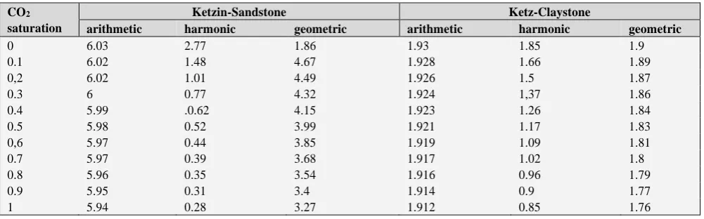
Table 1. Bulk rock thermal conductivity (W MK-1) for different saturations of carbon injected carbon dioxide6
To justify the use of the harmonic averaging technique in computing the effective thermal diffusivity requires due reverence to a typical case of harmonic mean application population genetics statistical analysis. In population genetics the harmonic mean is used when calculating the effects of fluctuations in generation size on the effective breeding population. Invariably this considers the fact that a limited size of the generation is like a bottle neck and means that a very small number of individuals are contributing disproportionately to the gene pool which can result in higher levels of inbreeding.
The significance of the bottle neck concept can be appreciated by noting that the rate at which water is poured out of a bottle depends on the size of the bottle’s neck. In this regard the neck of the bottle is a major contributor to the rate. For a two face flow involving the injection of carbon dioxide into a saline aquifer for storage and the resulting displacement of the resident brine the bottle neck concept applies in the sense that the effective thermal diffusivity given by Equation (20) changes with saturation and it is mostly governed by the saturation of the injected gas that is supposed to occupy the porous medium by displacing the resident fluid.
Using Equation (21) the effective thermal conductivity K
will be calculated as:
(22)
The effective value of the product of density and heat capacity of the system is calculated similarly as:
(23)
The equivalent thermal diffusivity can now be written as:
(24)
Using mixing rule and the harmonic mean concept, Equation (24) gives the effective thermal diffusivity of the system as a function of water saturation. Equation (15) will henceforth be written as:
(25)
An Approximation to the energy balance equation
To obtain an approximation to the energy balance equation obtained previously two physical realities will be duly exploited.
They are the relatively high hydraulic diffusivity of the system compared to the low thermal diffusivity of heat.4
CO2
saturation
Ketzin-Sandstone Ketz-Claystone
arithmetic harmonic geometric arithmetic harmonic geometric
0 6.03 2.77 1.86 1.93 1.85 1.9
0.1 6.02 1.48 4.67 1.928 1.66 1.89
0,2 6.02 1.01 4.49 1.926 1.5 1.87
0.3 6 0.77 4.32 1.924 1,37 1.86
0.4 5.99 .0.62 4.15 1.923 1.26 1.84
0.5 5.98 0.52 3.99 1.921 1.17 1.83
0,6 5.97 0.44 3.85 1.919 1.09 1.81
0.7 5.97 0.39 3.68 1.917 1.02 1.8
0.8 5.96 0.35 3.54 1.916 0.96 1.79
0.9 5.95 0.31 3.4 1.914 0.9 1.77
1 5.94 0.28 3.27 1.912 0.85 1.76
2 2 2
s w CO2 CO2
s
w w w w w CO CO w CO s
p s w p w w p
2 s
eff 2
,
1 ,
1 1
, T r t
t
c S U s c S U T r t
r
c s c s c
T r t
r
2
2 2
CO2 CO2 w s
CO2 CO2 w s
eff
CO w w w s
CO w w w w w s s CO
p w p w w p s
p w p w w p s
1 1
2 *
1 1 1
1 1
1 1
K S K S K
K S K S K S K K K
c S c S c
c S c S c
2
2
2 2
eff
CO w w w s
CO w w w s
CO w w w w w s s CO w
3
1 1 1
1 1
3 1 1
1 1 1 (1 )
K
K S K S K
K S K S K
K S K S K S K K K S
w s
CO2 CO2 p eff
2 2 2 2 2
p w w p s
p w
3
1 1 1
1 1
c
c S c
c S
2 2 2
s CO2 CO2
s
w w w w w CO CO w CO s
p s w pw w w p
,
1 ,
1 1
0
T r t t
c S U s c S U T r t
r
c s c s c
This makes it possible to eliminate the diffusive part of the energy balance equation for the system.
The second is the decrease in effective thermal diffusivity of the system due to increase in injected gas saturation. In the light of carbon dioxide injection the effect would be to create higher gas saturations. Table 1 indicates the effect of gas saturation on bulk or effective thermal conductivity for a typical carbon geo-sequestration in a saline aquifer with an eminent decrease of this parameter with increasing gas saturation. The table shows a dramatic decrease for the case of a harmonic mean of thermal conductivity.
From Table 1 it is realized that since the concentration of gas is increasing the effective thermal conductivity of the system will be determined by gas saturation and since this decreases the ratio of this parameter to the effective volumetric heat capacity (effective value of the product of density and heat capacity for the elements of the system), a measure of effective thermal diffusivity will also decrease with gas saturation. By custom a comparison between diffusive and accumulation term gives:
(26)
This equation can be rearranged as:
(27)
where
tthdif and αe are thermal diffusive time scale and
effective diffusivity, respectively.
By Equation (27) the diffusive time scale will be given as:
(28)
Substituting for effective diffusivity gives:
(29)
Implications for Hydrodynamic Environments and Lithology
The transfer of heat between injected fluid and the solid grains of the porous medium will occur generally on a diffusive time scale given by:7, 8
(30)
where
tdiff, dg, and α are diffusive time scale, average grain
diameter, and thermal diffusivity of grain material, respectively.
On the other hand the time required for the injected fluid to migrate across a pore space is measure by:
(31)
where
tcon, s, and u are convective time scale, injected fluid
saturation, average sediments porosity and Darcy velocity, respectively.
For local thermal equilibrium criterion the convective time scale must be longer than the diffusive time8 scale and this
requires an average grain diameter:
(32)
This requires grains sizes in the range of 0.1 to 0.01 which is typically met by sandstone sedimentation environment. The implication is that near the injection well the zone acquires the temperature of the injected fluid while at the leading edge of the injected fluid the far field temperature of the formation persists. This leads to the creation of a transition zone.
If it is assumed that the value of thermal diffusivity is negligible and the diffusive time scale given by Equation (28) is not important then energy balance Equation (25) reduces to:
(33)
At a given time in the flow field the total flux in the system is written as:
e 2
thdif th
T T
t h
2 th thdif
e
h
t
e condiff eff
D th f
1
c t
t
c U h
2
2
2 2
w s
CO2 CO2
w s
CO2 CO2 e
diff
CO w w w
f
CO w w w s
con
th CO w w w w s s CO
p w p w w p s
p w p w w p s
1
*
2 1 1
*
1 1 1
1 1
*
1 1
w c t
c U S U S
K S K S K t
h K S K S K S K K K
c S c S c
c S c S c
2 g diff
d t
con
g
d s
t
u
g
s
d
u
(34)
where Q = injection rate.
Consequently the following can be written for the numerator of the coefficient of the space derivative on the right hand side of Equation (33):
(35)
This reduces Equation (33) to the following form:
(36)
Flow Velocity Field
The final equation for energy balance of the injected fluid must contain the appropriate form of the convective thermal energy transfer term. To be able to obtain this requires deducing the velocity field for the system. The following assumptions are considered pertinent:
1. The high differential thermal expansion mismatch between the fluids and the solid grains if the rock will cause the solid to resist the expansion of the fluids
2. The low thermal expansivity of the grains will cause small expansion of the grains
3. From assumptions 1 and 2 the resulting volume change due to temperature changes will be negligible
4. The effective compressibility of the system is negligible
On the basis of the above assumptions the flow rate of the injected fluid (gas) is calculated as:
(37)
Q, dV, dt are injection rate, volume flow and time interval, respectively in the flow field.
The relationship between fluid volume at a given radial distance, the wellbore radius, the thickness of the aquifer and porosity of the aquifer is given by:
(38)
where V, rw, r, h are volume flow, well radius, radial
distance and thickness of aquifer, respectively.
The change in volume is given by:
(39)
Substituting for volume change in Equation (39) into Equation (37) gives:
(40)
The change of radial distance with time is gas flow velocity given by:
(41)
where µ = velocity field Equation (40) becomes:
(42)
Multiplying Equation (42) through by well radius and rearranging gives:
(43)
In Equation (43) the cross sectional area Ac opened to gas
injection is given by:
(44)
Substitution of this into Equation (43) gives:
(45)
where U= injection velocity
2 2
2
tot w CO CO
CO rgiw
rwir w
w r g
Q U U U U
P Kk
Kk P
r
2
2 2 2
tot w CO
w w w w w CO CO 1 w CO
U U U
c
S U S c
S U
2 2
s w CO2 CO2
s
CO CO tot s
s w p w w p
,
, 0
1 p 1
T r t t
c U T r t
r
c s c s c
dt dV Q
2 2 2 2
w w
V
r h
r h
h
r
r
2 2
w 2 2
w 2
V r h r h
h r r r h r
t
r
rh
t
V
Q
2
u
t
r
u rh t
V
Q 2
c
2
wA
r h
w tot
r U
u
r
w
w
2 r Q
u rr h
2 2
s w CO2 CO2
CO CO w int
p
p s w p w w p
1
1
c
r U
U
c
s
c
s
c
r
The interstitial velocity is obtained by dividing the injection velocity by the porosity of the sediment as:
(46)
Substitution of Equation (46) into (45) gives:
(47)
This equation shows a decrease with radial distance from the well bore. Substitution of this into the energy balance Equation (36) gives:
(48)
Equation (48) is a linear hyperbolic partial differential equation where the temperature field propagates with a velocity Up given by:
(49)
The effective volumetric thermal capacity of the system is measured by the equation:
(50)
It is customary to assume that this parameter is independent of fluids saturations.9
Analytical Solution
The general form of Equation (48) reads:10
(51)
The analytical solution using maple program command is given by:
(52)
In order to obtain the function F the following boundary condition is used:
(53)
This means that at all times of injection the temperature of the sand face at the point of injection where the radial distance is zero must be realistically equal to that of the temperature of the injection fluid.
Substituting this boundary condition into Equation (52) gives F as:
(54)
Substituting this into Equation (52) gives:
(55)
Substituting temperature for u gives:
(56)
The value of b at a given irreducible water saturation will depend on the injection rate and the interfacial tension as well as the viscosity of the injected carbon dioxide and this is given by the capillary number. Equation (56) can be written in a dimensionless form by defining the following dimensionless variables:
(57)
where
rD, r, raq, TD, Tinj and T0 are dimensionless radius, radial
distance from sand face, dimensionless temperature, dimensionless injection temperature and initial temperature of formation, respectively.
(58)
where
tD, q, raq, h and t are dimensionless time, injection rate,
radius of aquifer, thickness of aquifer and time of injection, respectively.
tot int
U U
int
U r r u w
2 2
s w CO2 CO2
s
CO CO w int
p s w p w w p
s
,
*
1 1
, 1
0 T r t
t
c r U
c s c s c
T r t
r r
s w w
CO2 CO2efth 1 p s i p w 1 iw p
C
c
s c
s c
t r
1 0
u b u r
F F
t btb r F t r
u
,
2 2 ,
2
, )
inj
u o t
u
inj
u
F
t
inj 2 2inj
2 ,
2 2
u r tb t r
u r t u
t b t tb
inj 2 2inj
2
, 1
2 2
T r tb r
T r t T
t b tb
0D D
aq inj 0
,
, , T r t T
r
r T
r T T
D
w
2
aqq
t
t
r
r h
The final solution can be written as:
(59)
The dimensionless temperature corresponding to the injection temperature is calculated as:
(60)
Consequently Equation (48) becomes:
(61)
and
(62)
The derivation of petrophysical properties evolution with temperature in the flow field requires coupled thermal and petrophysical properties dependence on temperature models. Capillary pressure, apparent water saturation and contact angle dependence on temperature are expressed by the following:11
(63)
(64)
(65)
where S, PcT, Prf, 0, Trf, T,rf and are apparent water
saturation, capillary pressure at a given temperature T, reference capillary pressure, a parameter relating to temperature dependence of interfacial tension, reference temperature, temperature of interest, reference contact angle and contact angle at temperature of interest, , n and
m=1+1/n are empirical constants.
For a two phase flow of immiscible fluids in porous media McWhorter12 and Sunada presented the following
equations for the relative permeability of the wetting and non-wetting phase:
(66)
where krw,knr and λ are relative permeability of the wetting
phase fluid, relative permeability of the non-wetting phase fluid and pore size distribution index, respectively.
Discussion
In view of the desire to optimize oil recovery in both secondary and tertiary recoveries schemes, a number of researches with published data have been reported on wettability and its evolution under different conditions of operations, in response to changes in reservoir rock surface energies caused by interaction between different crude oil components.13 The objective of this analytical work is to
investigate the effect of non-isothermal two phase flow on contact angle and wettability and compare these with existing findings.
Figure 1. A plot of aquifer radial temperature profile for different times of gas injection
Consequently, to be able to better discuss the results of this analytical work in the context of reported trends in the petroleum industry there is the need to apply appropriate theories in areas related to these properties of the system.
D
2 2
inj D
D inj
D aq
2
1
2 2 2
T r tb qr
T T
t b t
r hb
D
inj 0
inj
inj 0
0,
T t T
T
T T
s 2 w2 CO2 CO2CO CO w int p
p s p w p
1
c r U
U
c c c r
cT rf
rf
T
P
P
T
m n
0 rf
w cT
0
1
T
S
P
T
rf rf
rf
cos
a bT
T
a bT
T
2 3
rw e
2 2
n r
1
w1
ek
S
k
s
S
2 2
s w CO2 CO2
s
CO CO w int s
p s w p w w p
,
, 1
0
1 1
T r t t
c r U T r t
r r
c s c s c
The following text will suffice to be able to explain some of the findings of this work.
In using Equations (65) and (66) for saturation and wettability computations 0.032 % of beta reported by Hugh and Brent11 was taken to be the representative of that of
carbon dioxide water system. This is in recognition of the percentage of this gas in the air. In view of wettability being a pore scale phenomenon a positive value of this was used for contact angle computations to account for wettability increase with temperature. Figure 1 shows a plot of aquifer radial temperature for different times of injection. This plot has been generated from the solution of the final energy balance Equation (48) which is a linear hyperbolic equation characteristic of wave phenomena in mathematical physics. Accordingly, the temperature field behaves in this manner. It shows that after half a month the thermal pulse had propagated to the aquifer boundary (500 m).This, therefore, shows a gradual increase in the ambient temperature of the system.
Figure 2. A plot of water saturation versus aquifer radial distance for different times of gas injection.
Figure 2 shows a plot of resident brine saturation as a function of aquifer radial distance for different times of injection. Accordingly, it shows that for longer times of injection water saturation close to the sand face or well face is lower and far away the saturation is hundred percent, meaning non invasion of injected gas.
Figure 3 shows injected gas saturation as a function of aquifer radial distance for different times of injection. It is worthy of note that one of the motivations for this paper is the desire to investigate the nature of the shock characteristic of the injected fluid the subject of which was
covered by the Bucley-Leverette theory of frontal advancement.14 In this theory application of mass balance to
the injected fluid results in a parabolic partial differential equation that is characteristic of diffusive processes. However, for high injection rates typical of the flow rate used in this work the effect of capillary forces that give rise to the diffusive nature of the mass balance equation is considered negligible and the overall result is a linear hyperbolic equation that describes saturation evolution with time and space. Under such conditions there is shock described by a saturation jump to a given frontal saturation and this depends on the initial value of the irreducible saturation of the injected fluid.15 The injection rates where
relative measure of viscous to capillary forces is extremely high a typical solution for saturation versus distance as a function of time will show viscous forces to be equal to ten times capillary forces. The exihits a typical shock characteristic of high injection rate where the ratio of viscous forces to capillary forces is 10. The nature of the shock is such that different saturations behind the shock propagate with a velocity equal to the frontal velocity.
Figure 3. A plot of injected gas saturation as a function of aquifer radial distance for different times of injection.
dependent capillary number theory the cosine of the contact angle will be higher close to the well bore and lower far away. The effect is to decrease the ratio of viscous to capillary forces. There is, therefore, a capillary dominated flow near the well bore and decreases far away from it. The effect is to create a curvature close to the well bore for all different times of injection gas saturation profile versus radial distance. This means that as the gravity of capillary forces diminishes the shapes of the shock approaches those with high viscous effect and with ratio of viscous to capillary forces of equal to 3.
Figure 4. A plot of irreducible water saturation versus aquifer radial distance for different times of gas injection.
This explains why gas saturation profile shows a curve near the well bore and a steep shape far away and this is quite consistent with the temperature dependent capillary number as explained earlier. The capillary number is the ratio of viscous to capillary forces but this has been defined in a number of ways pertaining to the physics of the problem in question. In this problem the interstitial capillary number has been found appropriate because it uses the interstitial velocity which is the superficial velocity divided by porosityof the sediment. Its appropriateness in the context of this paper stems from the fact that wettability is pore level phenomenon and deserves to be considered in the light of interstitial flow rather than superficial flow.
Figure 4 show a plot of irreducible water saturation as a function of radial distance for different times of injection. The finding in this work is consistent with those reported by Ancilotto et. al16 which indicated an increase in irreducible
water saturation for supercritical carbon dioxide and brine system. Accordingly irreducible water saturation is higher for longer times of injection as observed in Figure 4.
Figure 5. A plot of aquifer wettability evolution versus aquifer radial distance for different times of gas injection.
Figure 5 shows the wettability evolution of the aquifer carbon dioxide and water system under non-isothermal flow conditions. The wettability of a system is measured by the cosine of the contact angle. As explained previously, the contact angle decreases with temperature and this means an increase in the wettability of the system. The nature of the plot, however, reflects the boundary condition used for the solution of the energy balance equation. Accordingly at all times the temperature of the inlet or sand face is equal to that of the injected fluid [373 K]. Therefore, the ambient wettability jumps to that commensurate with this inlet temperature and decreases as the temperature decreases. Bikkina17 has reported a decrease in contact angle for carbon
dioxide water system for a silica surface. Schembre et.al18
have also reported a similar trend.
Conclusion
However, few published works exists in this area and these coupled with reported trends in contact angle obtained in different but similar areas of investigations (chemical physics) have provided a basis of comparison using analytical results from this work. In this regard the following conclusion can be drawn.
1. The effect of temperature gradient in immiscible two phase flow involving supercritical carbon dioxide and resident formation brine is to cause a curvature to be observed on the saturation shocks at regions close to the sand face and then dissipate far away from this resulting in a shock similar to those of isothermal conditions reported in the literature.
2. The effect of temperature gradient flow is to increase the wettability of the system close to the sand face and this evolves with time.
3. This analytical work has also established the positive temperature dependent nature of irreducible water saturation.
4. In the field of immiscible two-phase flow in porous media information about saturation evolution is always obtained from flow tests. This analytical work has provided a means of obtaining an idea about saturation evolution under non isothermal conditions.
Acknowledgements
The authors wish to acknowledge the support provided by Dalhousie University for computational work and Cape Breton University’s Office of Research and Graduate Studies for financial support.
Greek Letters
eff= effective thermal diffusivity, m2 s-1
= temperature dependence of interfacial tension, mN m-1
= Temperature gradient of surface tension, mN K-1
= velocity field
= contact angle, degrees
= density, kg m-3
References
1Sharer, R. J., and Traxler, L. P., The Ancient Maya, Stanford Univ. Press, USA. 2006, ISBN 0804748179
2Hildenbrand, A., Schlomer, S., Krooss, B. M., and Littke, R.,
Geofluids,2004, 4, 61-80.
3Zimmerman, R.W., Int. J. Rock Mechan. Mining Sci., 2000, 37, 79-87.
4Charlez, P. A., Rock Mechanics, Vol. 2 -Petroleum Application, Edition Technip, Paris, 1997.
5Minkowycz, W. J., Haji-Sheikh, A., and Vafai, K., Int. J. Heat
Mass Transfer, 1999, 42, 3373-3385.
6Hurter, S., Garnett, A., Bielinski. A, and Kopp, A., SPE Conf. Offshore Europe, September 4-7, 2007, Aberdeen, Scotland, U.K.
7Chou, Y., Statistical Analysis, Holt, Rinehart & Winston of Canada Ltd, 1975, 2nd edition, ISBN: 9780030894220. 8Rayward-Smith, W. J., and Woods, A. W., Geophys. Res. Lett.,
2011, 38(6). L06407, doi:10.1029/2010GL046412. 9Prats, M., J. Petroleum Techn.,1969, 1(3), 323-332.
10Strikwerda, J. C., Finite Difference Schemes and Partial
Differential Equations, Soc. Ind. Appl. Math., USA, 2004.
ISBN: 978-0-89871-567-5
11Hugh Y. S., and Brent, E. S., Water Resources Res., 1998, 34(10), 2587-2597.
12McWhorter, D. B and Sunada, D. K., Water Resources Res.,1990,
26(3), 339-413.
13Dixit, A. B., McDougall, S. R., Sorbie, K. S., and Buckley, J. S.,
SPE/DOE Improved Oil Recovery Symp., April 1-24, 1996,
Tulsa, Oklahoma.
14Yortsos, Y. C., and Fokas, A. S., SPE J.1983, 23(1), 115-124. 15Smith, C. R., Tracy, G. W., and Farrar, R. L., Applied Reservoir
Engineering, Oil and Gas Consult. Int. (OGCI), 1992, Tulsa, USA: paper by Ahmed A. Gawish, “The Compensation Study of Viscosity and Volume Changes in Natural Gases”. 16Ancilotto, F., Faccin, F., and Toigo, F., Phys. Rev. B, 2000,62.
17035-17042.
17Bikkina, P. K., Int. J. Greenhouse Gas Control, 2011, 5(5), 1259–1271.
18Schembre, J. M., Tang, G.-Q., and Kovscek, A. R., SPE Res.
Eval. Eng,2006, 9(3), 239-250. SPE-93831-PA.