Research Article
a
May
2019
Computer Science and Software Engineering
ISSN: 2277-128X (Volume-9, Issue-5)
Rectangular Shaped Patch Antenna Design for WLAN (2.4 GHz)
Prof. Sumedh V. Dhole1, Prof. P. B. Mane2
1
Assistant Professor, Department of Electronics Engineering, Bharati Vidyapeeth (Deemed to be University), College of Engineering, Pune, Maharashtra, India
2
Principal, A. I. S. S. M. S., Institute of Information Technology, Near Pune Railway-Station, Pune, Maharashtra, India
e-mail id: [email protected], [email protected]
Abstract— This paper include the review of design of patch Antenna. We have already analysed patch antennas with different variations of patch length, width, variations in dimensions of feed line and variations in dimensions of substrate.
The proposed review of design of patch Antenna includes the required impedance bandwidth variation necessary for 2.4 GHz for WLAN application. Microstrip Antenna which are simulated using Ansoft HFSS and the results such as Return loss, VSWR etc. are calculated for better bandwidth.
Keywords— Microstrip Patch Antenna, WLAN, wireless communication.
I. INTRODUCTION
Microstrip Patch Antenna designed using various structures are reviewed and thus studied and calculated for better Bandwidth.
Conventional MSA (Microstrip Antenna) in general has a conducting patch printed on a grounded microwave substrate and have the attractive features of low profile, light weight, easy fabrication etc.
Thus its simulated using Ansoft HFSS simulating software and calculations are made for its better Bandwidth achievement.
II. PATCH ANTENNA DESIGN Patch Antenna Dimensions:
The proposed MS Patch Antenna has following parameters : Patch:-Width:28.8(mm),Length:37.7(mm),Height:0.05(mm) Substrate:- Width :80(mm), Length :75(mm), Height:1.6(mm) Ground:-Width:80(mm)Length:75(mm),Height:0.05(mm) Air Box:- Width:100(mm),Length:100(mm),Height: 35(mm) Feed line:- Width :3(mm),Length:9(mm),Height:0.05(mm) Port:- Width:3(mm), Length:1.65(mm).
Fig: 1. „Microstrip Patch Antenna‟ simulated using HFSS for [2.4 GHz]
III. SOFTWARE SIMULATION
A. Simulation Results of RMSA:
ISSN(E): 2277-128X, ISSN(P): 2277-6451, pp. 49-55
Fig: 2 Return Loss(S11 Parameter)
As shown in above fig..2, the return loss has a single band for WLAN.
5.00 2.00 1.00 0.50 0.20 5.00 -5.00 2.00 -2.00 1.00 -1.00 0.50 -0.50 0.20 -0.20 0.00 -0.00 0 10 20 30 40 50 60 70 80 90 100 110 120 130 140 150 160 170 180 -170 -160 -150 -140 -130 -120 -110
-100 -90 -80 -70 -60 -50 -40 -30 -20 -10
Ansoft Corporation Smith Plot 1 HFSSDesign1
Curve Info S(LumpPort1,LumpPort1) Setup2 : Sw eep1
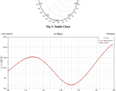
Fig 3: Smith Chart
ISSN(E): 2277-128X, ISSN(P): 2277-6451, pp. 49-55
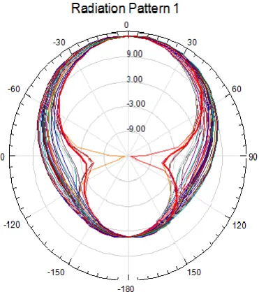
The Omni-Directional radiation pattern is observed as below fig.5:
Fig 5 : Polar radiation plot
IV. SIMULALATED RESULTS OF “PATCH MICROSTRIP ANTENNA”:
The Patch Microstrip Antenna with simulated results such as Return loss, VSWR and smith chart and radiation pattern are observed and maintained for better Bandwidth.
Fig 6: S11 paramenter of Patch Microstrip Antenna
With certain variation in simulation of Ground and Feed to antenna with SMA connector the results can be obtained as below.
Substrate:- Width :88(mm), Length :85(mm), Height:1.6(mm) Ground:-Width:80(mm)Length:75(mm),Height:0.05(mm) Air Box:- Width:100(mm),Length:100(mm),Height: 35(mm) Feed line:- Width :3(mm),Length:9(mm),Height:0.05(mm)
ISSN(E): 2277-128X, ISSN(P): 2277-6451, pp. 49-55
Whereas the above fig.7 shows two bands for WLAN.
Fig. 8: VSWR of „Dual Band Microstrip Antenna’
Fig 9: Polar radiation plot of Dual Band Microstrip Antenna’
ISSN(E): 2277-128X, ISSN(P): 2277-6451, pp. 49-55
1. Calculations for Microstrip Patch Antenna’:
A From Fig.2, at mark m1, the frequency is equal to 2.256 GHz and mark m2,the frequency is 2.441 GHz. Therefore the Impedance Bandwidth is
Band Width = (2.441-2.256) GHz = 0.185 GHz
= 185 MHz
Review for „Dual Band Microstrip Antenna’
Fig 6, Lower frequency fc1=2.4GHz with return loss= -15dB .
Similarly the %BW for lower central frequency fc1=m1=2.4GHz, can calculated as :
Impedance Bandwidth = fmax – fmin
=(2.6GHz- 2.15GHz) =0.45GHZ %BW= (fmax - fmin)*100/ fc1
% BW = (2.6GHz- 2.15GHz) *100 /2.4GHz %BW=19%
Thus the %Bandwidths for Dual band Omnidirectional MSA can be improved and thus we can say that it ma y
be used for UWB operation , and also the Return loss can be reduced upto -35dB.
“We know that if percentage bandwidth is greater than 25%, then its called as Ultra Wide Band.”
Here the S11 Parameter is -33.15dB at mark m3 i.e. Center Frequency Fc=2.414703 GHz
To get Impedance Bandwidth for Higher Frequency [5.1 GHz]:
Consider the higher frequency band in Dual Band Microstrip Antenna’ from fig.6 , the Higher frequency fc2=5.3GHz with return loss= -13dB.
The value fmax = m4= 6.77GHzand the value of fmin=m3=4.36GHzand fc2= 5.2GHz
Impedance bandwidth= fmax - fmin
=6.77GHz – 4.33GHz =2.4 GHz
Therefore %BW is given bym, %BW=(fmax - fmin)*100/ fc2
% BW = 2.4GHz*100 /5.2GHz Hence % BW = 46%
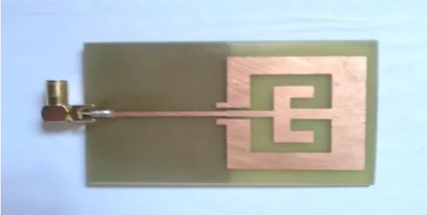
V. HARDWARE IMPLEMENTATION
Hardware of „ Microstrip Patch Antenna’
Fig 11: H/W of Dual Band Microstrip Antenna‟
Hardware results of RMSA
ISSN(E): 2277-128X, ISSN(P): 2277-6451, pp. 49-55
Fig 12: S11 parameter of RMSA with Network Analyzer.
Fig 13: Measured Smith Chart of RMSA
The smith chart is as shown above.
Fig 14: Measured VSWR of Patch Antenna.
VI. CONCLUSIONS
Thus Microstrip patch antennas at 2.4 GHz are simulated, designed and also tested for various parameters like SWR, S11, etc using network analyzer.
ISSN(E): 2277-128X, ISSN(P): 2277-6451, pp. 49-55
REFERENCES
[1] S. V. Dhole & P.B.Mane, “OMNI-DIRECTIONAL DUAL BAND[2.4GHZ AND 5.1GHZ] MICRO-STRIP ANTENNA FOR WLAN”, International Conference on electrical and electronics engineering , 27th
Jan 2013, Goa.
[2] A Compact Broadband Planar Antenna for GPS, DCS-1800, IMT-2000, and WLAN Applications(1536-1225/$25.00 © 2007 IEEE)UWB Antennas and Channel Characteristics E. Pancera IRE, KIT, Germany(978-1-4244-7092-1/10/$26.00 ©2010 IEEE)
[3] A. A. Saeed & Shoukry I. Shams “Compact Multiband Omni-Directional Printed Antenna”, 14th International Symposium on Antenna Technology and applied Electromagnetics [ANTEM] and the American Electromagnetics Conference[AMEREM], 2010.
[4] A New Printed Antenna for Multiband Wireless Applications Yi-Chieh Lee, Student Member, IEEE, and Jwo-Shiun Sun 1536-1225/$25.00 © 2009 IEEE
[5] A Compact Broadband Planar Antenna for GPS, DCS-1800, IMT-2000, and WLAN ApplicationsRongLin Li, Senior Member, IEEE, Bo Pan, Joy Laskar, Fellow, IEEE, and Manos M. Tentzeris, Senior Member, IEEE (1536-1225/$25.00 © 2007 IEEE)
[6] Dual-band printed antenna for mobile telephone applications D.Viratelle and R.J.Langley, IEE l‟roc -Mici.oio Aiiroii7o.s 1‟~o~mg.V. ol. 147, No. 5, 0ctohc.i. 2000.
[7] D. Sievenpiper et al., “High-impedance electromagnetic surfaces with a forbidden frequency band,” IEEE Transactions on Microwave Theory and Techniques, vol. 47, pp. 2059-2074, Nov.1999.
[8] C. A. Balanis, Antenna Theory: Analysis and Design, 3rd ed. WileyInterscience, 2005. [9] K.P.Ray, Broadband Microstrip Antenna, Artech House,Boston,2003.