Proceedings of the
Second International Workshop on
Visual Formalisms for Patterns
(VFfP 2010)
Patterns of Federated Identity Management Systems
as Architectural Reconfigurations
1Hyder Ali Nizamani and Emilio Tuosto
14 pages
Guest Editors: Paolo Bottoni, Esther Guerra, Juan de Lara
Managing Editors: Tiziana Margaria, Julia Padberg, Gabriele Taentzer
Patterns of Federated Identity Management Systems
as Architectural Reconfigurations
†Hyder Ali Nizamani1and Emilio Tuosto2
1[email protected],2[email protected]
Department of Computer Science University of Leicester, UK
Abstract: This paper proposes a formal model of Federated Identity Management systems (FIMs) in terms of architectural design rewriting. FIMs allow cross-domain user authentication to enable access control across the organisations under the con-cept known as Circle of Trust (CoT). Patterns of FIMs emerged as recurring CoT scenarios due to the fact that each of the pattern has different security and trust requirements. This paper proposes a formal model for FIMs to characterise their patterns as architectural styles. More precisely, an architectural style is given to precisely pinpoint all possible legal configurations of the CoT in terms of the pat-terns. The proposed model is specified through style-consistent (graphical) designs in terms of architectural design rewriting (ADR).
Keywords:Modelling, Federation, Identity Management, Circle of Trust, Patterns, Architectural Style, Reconfigurations.
1
Introduction
We give a definition of patterns emerging forfederated identity management systems(FIMs) in a formal model of graph transformation. In particular, we show how patterns can be formally specified as architectural styles along with a representation of FIMs in a formal framework can suitably express transformations of their patterns.
The fundamental goal of FIMs is to share identity related information for cross-domain user authentication through some protocols and standards [15, 13, 11]. Typically, federations are created and managed by establishing legal (i.e., business, administrative, etc.) relationships by a set of contracts that specifies obligations and rights together with the policies each organisation has to follow [12]. These federated organisations form a Circle of Trust (CoT) that can be defined as a group of Service Providers (SPs) and Identity Providers (IDPs). Roughly upon requests to the services, the SP uses identity related information to enforce access control.
Nowadays, FIMs implementations may be found in various domains (i.e., finance, education, healthcare, etc.) and such systems are considered relatively static due to the nature of the CoT. However, a dynamic approach may be realised that enables organisations leaving or joining the CoTs to take some economic benefits in today’s emerging dynamic and scalable systems (e.g., Clouds and Web 2.0). In this way, one can take advantages of service-oriented computing (SoC) that can provide not only functional but some non-functional requirements (i.e., security) as
services. For instance, FIMs can be used to deal with access control in a cloud. Consequently, architectural modeling of these systems becomes necessary; for instance, in current distributed systems the possibility to tackle (dynamic) changes is paramount. Remarkably, this reflects at the architectural level and requires what is known as architecturalreconfiguration. Architectural styles may provide a suitable mechanism for guiding the reconfigurations in a way that any change in the architecture does not violate the style. At the best of our knowledge, only informal FIMs models have been given; in [12,7] some interesting FIMs patterns are presented in terms of security and trust requirements.
This paper focuses on modeling architectural aspects of FIMs that are validated against the patterns given in [12] and introduces an architectural style for the purpose. Architectural aspects of FIMs are formalised usingArchitectural Design Rewriting(ADR) that is a graphical formal-ism introduced in [4,5] to formally specify architectural aspects of systems. The architectural styles corresponding to the patterns in [12] are formally characterised by a type graph and a few ADR productions. The type graph specifies the architectural elements of FIMs by describing components (edges) and their legal interconnections (nodes) while ADR productions formalise refinement. In fact, a selected FIMs pattern is generated by some design productions that guar-antee a valid CoT by construction; for instance, as shown later, the constraint that a legal CoT configuration must have at least one IDP and one SP is formalised by suitable productions. In other words, architectural styles can model well-formedness conditions of FIMs as well as the patterns induced by the security and trust requirements studied in [4,5].
The main motivations for using ADR are (i) that it is a mathematically precise framework,
(ii) that ADR allows style-based design and, more importantly, (iii)that ADR features style-preserving reconfigurations of software architectures. Noteworthy, style-style-preserving reconfigura-tions are not naturally supported by other architectural description languages (cf. [6]). In ADR instead, style-preserving reconfigurations can be enforced by imposing simple conditions on the format of reconfiguration rules. More precisely, an ADR reconfiguration rule has the form
r:t→t0 (1)
wheretandt0are typed terms of an algebra induced by the graph rewriting mechanisms of ADR (i.e., productions); an ADR reconfiguration system is a set of rules wheretandt0have the same type for each rule (1). Remarkably, style-preserving reconfigurations are paramount for FIMs as violations of well-formedness may hinder their correctness (security and trust requirements).
Structure of the paper §2briefly describes the concept of FIMs, some of their patterns, and basic definitions of ADR. The ADR model of FIMs is in §3. Architectural configurations of the selected FIM patterns are in §4and their reconfigurations are addressed in §5. Related work is given in §6. Finally, the summary and the future research directions are briefly described in §7.
2
Background
2.1 Federated Identity Management
FIMs forms an interesting class of distributed systems that allow group of organisations to “fed-erate” to share services (or resources). Typically, sharing distributed resources requires an access control system to authenticate users. FIMs make users’ authentication information available in a global context so that organisations can be part of different federations and have more business relationships with different group of organisations.
The roles involved in FIMs are
• users (whose identity is to be federated),
• identity providers (IDP), and
• service providers (SP)
where IDP vouch authentication statements for users (e.g., by issuing certificate) and SP dispense services.
Example1 A university can be part of a federation of digital libraries, in which case the uni-versity is the IDP, each library is an SP, and students and staff are users.
The notion ofCircle of Trust(CoT) is key to FIMs and permits to establish complex contracts that describe common policies and obligations. In [1], a CoT is defined as a framework that specifies a common set of cooperation policies together with collaboration interfaces within a certain group of organisations having trusted relationships. Users provide verified identities in order to access resources shared by member organisations of the CoT. FIMs allow users from different organisations to be authenticated when accessing remote resources in their CoT [16]. In FIMs, a CoT can be described as a federation of identity and service provider organisations.
FIMs are becoming ubiquitous and can be found in many different application contexts, in-cluding eCommerce, education, eHealth, eGovernment.
Example 2 (cf. [10]) A financial institution needs its users (employees, customers, etc.) to access services offered by a third party provider. The financial institution is the IDP managing the authentication information of its users to the third party SP. The financial institution (IDP)
authenticates its users to grant them access to SP’s resources.
security threats they are subject to, pattern (i) being the “most robust”. We now briefly comment on the security threats hindering each pattern (see [12] for details).
In (i), a single IDP is federated to a single SP and they agree to deal with the private data according to common policies. Since the access to services is mediated by the IDP, the latter is aware of users’ activities (e.g., how often users communicate with the SP). The IDP may exploit this kind of information to acquire knowledge on users’ behaviour and this is regarded as a threat to users’ privacy. Also, SP receives information related to users’ identity from the IDP hence the SP might disclose (i.e., to other SPs) such information without the consent of the IDP or the user. In (ii), a single SP is federated to multiple IDPs; users may be registered at several IDPs and they notify the SP about which IDPs will be used for authentication. The additional threat with respect to pattern (i) is that some or all IDPs might decide to cross-check the information about the accesses to the SP.
In (iii), a single IDP is federated to multiple SPs; a typical situation in this case is that delega-tion of user authenticadelega-tion is necessary. For instance, a service in the federadelega-tion may be delegated (by an IDP or by another SP) to provide users’ credentials if it needs to invoke other services in the federation. The additional threats with respect to pattern (ii) include unauthorised delegation of authentication and “collusion” of SPs to accumulate identity information. The first threat may happen when users invoke a complex service that needs to make further invocations to other SPs in the federation. The second threat is quite serious as it would allow SPs to correlate their information and accumulate data on users.
Pattern (iv) is the most vulnerable as it allows the free combination of patterns (i-iii) and is exposed to all their threats.
2.2 Architectural Design Rewriting
The Architectural Design Rewriting(ADR) approach [4,5] permits to design hierarchical and reconfigurable software architectures. The main features of ADR include a rule-based approach, hierarchical design, and an algebraic presentation. We borrow the main definitions of ADR from [4] (where more details can be found).
Software architectures are modeled in ADR as hypergraphs whose edges represent compo-nents and nodes (vertices) represent interconnections between the compocompo-nents.
Definition 1([4]) A(hyper)graphis a tupleG=hV,E,tiwhereV is the set of nodes,Eis the set of edges andt:E→V∗is the tentacle function.
Example3 An ADR graph on the sets{},•}(of nodes) and{N,T}(of edges) can be graphi-cally represented as
}oo N •oo T (2)
The tentacle function is represented by the lines connecting edges ordered clockwise starting from the arrow-headed tentacle; the tentacle function of (2) mapsNto[},},•]andT to[•].
Definition 2([4]) A graphGistyped over a graphHwhen Gis homomorphic toH, namely when there are fV :VG→VH and fE :EG→EHpreserving the tentacle functions, i.e. fV∗◦tG= tH◦fE, where fV∗is the homomorphic extension of fV toVG∗.
Architectures are modeled using designs which represent architectural components with their interconnections. Architectures can be composed usingdesign productions.
Definition 3([4]) Adesignis a graph with interface, i.e. a tripled=hLd,Rd,idi, whereLdis a (typed) graph consisting only of a nonterminal and by distinct nodes attached to its tentacles;Rd is a (typed) graph without nonterminal edges; andid:VLd →VRd is a total function.
A(design) production pis a tuplehLp,Rp,ip,li whereLpis a (typed) graph consisting only of a nonterminal labeled by sayApand by distinct nodes attached to its tentacles;Rpis a (typed) graph with both terminal and non-terminal edges;ip:VLp →VRp is a type preserving function; andlis a bijection mapping the non-terminal edges ofRp on an initial segment[1,2, . . . ,np]of positive numbers. Given a production pas above, callLpthe left-hand-side (LHS) of pandRp the right-hand-side (RHS) ofp.
Productions allow top-down design by refinement, bottom-up typing of the actual architecture and well-formed composition of the architectures. The set of design productions together with the type graph represent the architectural style.
Example4 Productions have a convenient graphical representation which we illustrate with an example. The graphsG1andG2below can be typed over the graph (2) in the obvious way
graphG1
}
c1 oo C0 c}2 •
p1
graphG2
}
a oo C1
I I I I }
b oo C2 uuuu
}
c
•
d
Ignoring the labelling function, the production with LHS G1 and RHS G2 (together with the homomorphisms) can be drawn as
C0:N
}
c1 }a oo C1:N }b oo C2:N }c c}2
d
•
p1•
(3)
where the outermost dotted box corresponds toG1, the inner graph isG2(with the explicit typing
given by the homomorphism), and the dotted lines map the nodes ofG1to those ofG2.
If non-terminal edges are considered as ’types’ (of architectures), ADR productions have a convenient “functional” reading illustrated continuing Example4.
In ADR, the design rules can be given an algebraic formulation where a term describes a par-ticular style-proof (asp(p(x,y),x)in Example5). Style-preserving reconfigurations are operated at the level of style-proofs by exploiting term rewriting over style-proof terms. A graph transfor-mation rule can be represented as a rewrite ruleL−→R; ifLandRare terms of the same type the rule is style-preserving [5].
Let us define a reconfiguration rule to add components (at abstract level) to the architectures of typeNgiven by the production in Example5and a productionq:N→Nthat takes a config-uration of typeNand returns another configuration of typeN. To illustrate this, assumexandy are architectures of typeNand consider the reconfiguration rule
add(y):q(x)−→p(q(x),y)
where a sub-termq(x)of typeNon the LHS of the rule is replaced by termp(q(x),y)of the same type on the RHS. Now, we demonstrate how to apply such a rule to reconfigure an architecture of typeN. For instance, the reconfiguration
p(q(x1),y1)−→p(p(q(x1),y2),y1)
is obtained by applying the ruleaddto the subtermq(x1)on the LHS so to yield the term on the RHS wherey2is attached in the new configuration by means of the constructorp.
3
Modeling FIM systems in ADR
We define FIMs architectures in terms of ADR productions on the type graph depicted in (4) which yields the vocabulary for the architectural elements of FIMs
CoT
• }federation chain
} P0
/
/
P1
/
/
IPs
SPs
o
o
IDP
o
o
SP
o
o
◦federation access
F
O
O
◦ •provider access
(4)
The graph (4) yields the types of components and nodes represent the kind of ports used to connect them. More precisely, federation chain nodes}are used to form chains of edges of type F or CoT; federation access nodes◦connect IDP and SP providers with a federation F; provider access nodes•connect providers. Formally, the type graph (4) and is defined as
VH={},◦,•}
EH={CoT,F,P0,P1,IPs,SPs,IDP,SP}
tH:
CoT7−→[},},•]
F7−→[},},◦]
P0,P1,IPs,SPs,IDP,SP7−→[◦,•]
chain: CoT×CoT→CoT ct0:CoT
}
c1 }a oo C1:CoT }b oo C2:CoT }d c}2
c
• p•1
(a) CoT Chain
fed: P1×P0→CoT ct0:CoT
c1
} }a oo f:F }b
c2
}
c
◦oo pi:P0 d• p•1
ps:P1
g
g
OOOO ttt
(b) CoT in a federation
Figure 1: A CoT and a chain of CoT
federation in FIMs. These providers can be obtained by refining non-terminal edges; for exam-ple, by refining non-terminal edges of type P0and IPs configurations with identity providers can be obtained, while configurations with service providers are obtained by refining non-terminal edges of type P1and SPs. The terminal edges F, IDP, and SP are the types for a federation, an identity provider, and a service provider respectively.
Figure1 shows productionschainandfedthat refine non-terminal edge CoT into a federa-tion of providers and chain of CoTs. Notice that LHS and RHS of producfedera-tions are typed over the graph (4). Production chain catenates CoTsC1 andC2 by connecting them on nodeb as illustrated in Figure1(a). Also, nodec is used to connectC1 andC2 to providers and exported together witha andd to possibly extend the chain. Productionfedgenerates configurations of CoT by connecting several providers (obtained by refiningpiandps) to each other and to a fed-eration f as illustrated in Figure 1(b). Providers pi and ps interact with federation f through nodec of type◦; nodesc1 andc2 allow f to connect to other CoT and node p1 to connect to other providers. Observe thatc1,c2, andp1are the nodes of the LHS offedcorresponding to the nodes of the RHS as specified by the dotted lines and ’exported’ in the interface offed; also, p1 allows providers generated bypsandpito connect to providers in other CoTs.
Figure2shows the productions to generate configurations of identity providers for P0in pro-ductionfed. Productionpips generates a configuration consisting of an IPs and an IDP. Pro-ductionipsgenerates configuration with many IPs (obtained by refining ip1 andip2). Finally, productionsipandnoipyield non refinable configurations;ipgenerates a single identity provider iwhilenoipgenerates an empty configuration. The productions for generating service providers are similar to those in Figure2and they are reported in AppendixA.
We illustrate how the legal configurations of FIMs in (5) can be derived using the productions given above, by refiningG1intoG2
G1=
}oo C1:CoT }
• G2=
}oo f:F
D D D
D } ps:P1
i:IDP //◦ •
pips: IPs→P0 ips: IPs×IPs→IPs ip:→IPs noip:→IPs
p0
:P0
◦ f1
◦ a pi :IPs o o b•
p1•
i
:IDP
f
f
N NN N u u u
ip
:IPs
◦ f1 ◦ a ip1 :IPs o o b •
p1•
ip2
:IPs
f
f
M MM M u u u
ips
:IPs
◦ f1 ◦ a i :IDP o o b •
p1•
ips
:IPs
◦ f1
◦ a b •
p1•
Figure 2: The Productions for Identity Providers
(G1andG2are typed over (4) in the obvious way). The initial sequence of reductions is
G1 fed →
}oo f:F }
◦oo pi:P0 •
ps:P1
b
b
FFFF {{{ {
pips →
}oo f:F } ◦oo i:IDP •
pi:IPs
b
b
ps:P1
\
\ JJJJ noip→
}oo f:F
D D D
D } ps:P1
i:IDP //◦ •
Namely, in the first step,fedis applied to generate the federation f; then the edge piis refined by applyingpipsyielding a providerpi of type IPs and a provideriof type IDP. Finally, config-urationG2is obtained by applying noipwhich cancels the non-terminal pi. Any configuration xrefining P1yields a term-like representation ofG2asfed(pips(noip),x)which highlights the hierarchical structure of the FIMs configurationG2. In this way, the FIMs patterns can be gener-ated and are illustrgener-ated in the next section.
4
Architectural configurations of the FIM patterns
We show how to generate the architectural configurations of the FIM patterns described in §2.1. It is worth remarking that a configuration in ADR is generated by applying productions. More-over, ADR configurations can be given a representation as a term of a suitable algebra. Such terms formalise FIMs patterns whose configuration is specified in the graphs corresponding to terms. To illustrate this, we apply the productions for FIMs and the approach given in §3 to some simple examples.
Let us begin with the pattern (i). The configuration with a single IDP and a single SP is gener-ated by applying productionfedfirst then followed by a refinement of the non-terminal edges P0 and P1(introduced byfed). In the second step indeed, productionspipsgenerates the configura-tion for P0consisting of a terminal IDP and a non-terminal IPs (and, similarly, productionspsps
generates the configuration for P1that consists of a terminal SP and a non-terminal SPs). Observe that the obtained graph contains non-terminal edges IPs and SPs (introduced by applyingpips
andpsps, respectively); these (spurious) non-terminal edges are cancelled using the productions
c1
}oo :F
c2
}
◦
f1
:IDP
<
<
x x x •
p1 :SP
b
b
DDD
(a) Bilateral federation
c1
}oo :F
c2
}
:IDP //
F F F f◦1
:IDP
<
<
x x x •
p1 :SP
b
b
DDD
(b) Multiple IDPs federation
Figure 3: Some architectural configurations of the CoT in FIMs
represented in Figure3(a) (where edge names are omitted as immaterial). In ADR, such config-urations can be given an algebraic formulation; for instance, the configuration in Figure3(a) is given by the termfed(pips(noip),psps(nosp)).
An example of bilateral federation can be given by a scenario where an airline is federated to a hotel to allow a traveler to book a room after booking a flight; the traveler may use his/her airline account to access the hotel and book a room without need to be re-authenticated (in this case, the airline would act as IDP and the hotel as SP).
A configuration of pattern (ii) can be generated in a similar way as done for the configuration of pattern (i). For instance, consider the case where two IDPs are federated to a single SP. Initially, the same sequence of productions can be followed that is used above for generating configuration of pattern (i) where a single IDP is federated to a single SP, with the difference that before applying thenoipproduction, the non-terminal pi in the productionpipsis further refined using the productionips. This introduces an additional IDP where eitherip1 orip2 in the productionipsis on turn refined by applying productionip, while the other non-terminal is canceled using productionsnoip. In this way, a configuration for pattern (ii) is obtained; its term representation is
fed(pips(ips(ip,noip)),psps(nosp))
and its graphical representation is in Figure 3(b). Example 6illustrates a scenario where this pattern may be useful.
Example6 Suppose that the scenario described above has to be modified so that travellers are authenticated either by the airline company or via another account on train company. In other words the airline and the train companies act as IDPs while the hotel is the SP. According to pattern (ii), a traveler can book a room after booking a flight or a train.
Configurations for the other patterns can be obtained in a similar way and examples are omitted for space limits.
enforce the creation of a legal CoT having at least one IDP and SP i.e., pattern (i). For confor-mance of rest of FIMs patterns i.e., patterns (ii-iv), one has to take into account the occurrences of productionsipandspin the terms to enumerate IDPs and SPs respectively.
In the next section we show how reconfigurations can be described.
5
Architectural reconfigurations of the FIM patterns
Architectural styles may offer a suitable modelling mechanism to guide the changes at the ar-chitectural level; in fact, patterns for FIMs can be given in terms of ADR arar-chitectural style as illustrated in §4.
At run time, systems may need to be reconfigured; for instance, adding one or more compo-nents. Noticeably, such changes may need to be reflected at the architectural level, namely they may induce architectural reconfiguration. FIMs are no exception. The architectures of FIMs patterns may evolve during the life of their CoTs where IDPs and SPs can be added to the feder-ations. For instance, the configuration of the pattern (i) consists of an airline (i.e., the IDP) and a hotel (i.e., the SP) can be reconfigured by introducing a train service (i.e., a new IDP). Such a change (adding an additional IDP) in the architecture reshapes the systems from pattern (i) to pattern (ii) so to allow users to book a room after booking a flightora train.
This change of pattern can be defined at basiclevel (namely, one IDP, or one SP, or one instance of both is added) as well as atabstractlevel (namely, arbitrary collections of IDPs or SPs are added at once).
ADR offers a graphical support and a formal mechanism to deal withstyle-preserving archi-tectural reconfigurations, namely archiarchi-tectural reconfigurations that do not modify the style. We remark that is crucial for FIMs as style preserving reconfigurations correspond to modifying con-figurations by changing their pattern while preserving a valid (legal) architecture. ADR can also express reconfigurations that violate styles. For instance, it is easy to define reconfiguration rules that cancel components so to obtain configurations without e.g., IDPs that are not considered valid FIMs. It is also worth remarking that the condition to preserve style is very simple; it is just necessary to ensure that LHS and RHS of the reconfiguration rule have the same type.
As we have seen in §3, the design rules can be given an algebraic formulation where a term in ADR describes a particular style-proof.
In order to illustrate how ADR reconfiguration rules can describe variations of FIMs we con-sider the following rules.
addIDP:noip−→ips(ip,noip) (6) addIDPs(X):noip−→ips(X,noip) (7)
c1
}oo :F
c2
}
◦
f1
:IDP
<
<
x x x •
p1 :SP
b
b
DDD −→
c1
}oo :F
c2
}
:IDP //
F F F f◦1
:IDP
<
<
x x x •
p1 :SP
b
b
DDD
Figure 4: Rule to add an identity provider (from left to right)
not change the architectural style. Similarly, rules can be defined that add one or more SPs to the configurations of FIM patterns.
Table 1: Effects of basic reconfiguration rules on FIMs patterns
Rules (i) to (ii) (i) to (iii) (ii) to (iv) (iii) to (iv) (i) to (iv)
Add a single IDP X X X
Add a single SP X X X
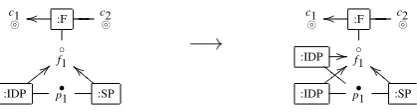
Table1shows the effects of basic reconfiguration rules that add a single IDP and a single SP on FIMs patterns (i-iv). Figure4(for simplicity, names of the edges are omitted) illustrates the reconfiguration of pattern (i) into pattern (ii) architecture by applying rule (6). The LHS graph shows configuration of pattern (i) consisting of an IDP (i.e., an airline) and an SP (i.e., a ho-tel). This architecture, is reconfigured by introducing an additional IDP (i.e., a train service) that yields a new configuration (RHS graph) that confirms to pattern (ii) with multiple IDPs federa-tion. To illustrate such a change in the configuration obtained by applying rule (6), transition
fed(pips(noip),psps(nosp))−→fed(pips(ips(ip,noip)),psps(nosp))
describes the reconfiguration where the LHS term defines configuration of pattern (i) while the RHS term defines the new configuration that represent pattern (ii). In this reconfiguration, sub-termnoipof type IPs on the LHS replaced with a new termips(ip,noip)of same type on the RHS. Such a transition preserve the FIMs style. Similarly, the effects of applying the rule that adds anSPreconfigures the architecture of pattern (i) to pattern (iii). Moreover, rule (6) and the rule that add an SP can be applied together to reconfigure the architecture of pattern (i) to pattern (iv). Furthermore, these rules can be applied separately while moving from patterns (ii-iii) to pattern (iv), for instance; rule (6) can be used to move from pattern (iii) to pattern (iv) and the rule that add an SP to move from pattern (ii) to pattern (iv).
6
Related Work
reconfiguration) aspects. In [12], various federation patterns are described in terms of security and trust requirements. We formalise the patterns that are based on direct trust relationships, namely relationships not relying on third parties (cf. [12]).
In [17] two new types of representation models are introduced; such models are called di-mension graph (DG) and pattern graph (PG). The former shows the relationship (pattern-to-dimension) of a pattern with respect to various “dimensions” (i.e., life cycle stage, architectural level1, security concern, business domain, type of pattern, and regulations/policies) of classifica-tion of security patterns. Instead, PG shows the relaclassifica-tionship (pattern-to-pattern) of a pattern to other patterns. In [17], the focus is on representing properties (e.g., what pattern can be used for certain purposes) of the security patterns and relationships (e.g., what kind of patterns can be used at the next stage to realise a given pattern) between the security patterns using a metamodel in UML class diagram. The metamodel is then used to create DG and PG as its instances rep-resented in UML object diagrams so to introduce an improved classification of security patterns that helps the designers in analysing, finding, and understanding security patterns at each level of the development process. We propose a generic architectural model that represents a class of FIMs patterns using a formal and a graphical approach. Our goal is the modelling of (direct se-curity and trust) relationships between the collaborating organisations at an abstract architectural level. We represent FIMs patterns as instances (typed graphs) of the model whose corresponding terms precisely show their construction. Moreover, reconfiguration rules and their relationships have been defined in terms of their effects on the architectures of given FIMs patterns.
An informal pattern system for authentication and authorisation infrastructures (AAIs) has been described in [8] by showing the possible interactions between the patterns given in [7,14]. In [8], the focus is on security aspects at implementation level and can be used directly in the software development process such as to deal with security in web services. The purpose of our work is twofold, one to formally model FIMs as an architectural style and other to deal with changes in their architectures while respecting the FIMs style. We provide a mechanism to for-mally model FIM at an abstract level that may be used for concrete implementation for detailed analysis of the FIMs properties (i.e., privacy) while allowing reconfiguration in the FIMs.
Finally, in [3] ADR has been promoted to model some aspects of SOA by proposing an archi-tectural style for a modelling language featuring module composition. FIMs patterns could be modelled following the approach described in [2] where ADR has been used as a formal support of style-based designs and reconfiguration of a UML profile for SOA. However, such approach would require OCL constraints to represent FIMs which are complex to deal with in the FIMs context.
7
Summary and Future Work
In this paper, an architectural style for modeling the FIMs patterns is given in terms of ADR pro-ductions. More precisely, an architectural style is used to formally generate the architectures of the selected FIMs patterns that conform to the valid CoT configurations. Also, reconfigurations of these patterns are addressed in a way that any application of the reconfiguration preserves the style.
Currently, we are working on some inductively defined reconfiguration rules for FIMs. More-over, we also intend to investigate the possibility of modeling behavioural aspects using [9] in order to support the execution of FIMs architectures.
Finally, one or more architectural styles for FIMs may be designed in the future to support more complex patterns such as to model indirect trust relationships (i.e., through trusted third parties) between the collaborating organisations.
Bibliography
[1] Latifa Boursas and Vitalian A. Danciu. Dynamic inter-organizational cooperation setup in circle-of-trust environments. InNOMS, 2008.
[2] Roberto Bruni, Matthias M. H¨olzl, Nora Koch, Alberto Lluch-Lafuente, Philip Mayer, Ugo Montanari, Andreas Schroeder, and Martin Wirsing. A Service-Oriented UML Profile with Formal Support. InICSOC, 2009.
[3] Roberto Bruni, Alberto Lluch-Lafuente, Ugo Montanari, and Emilio Tuosto. Service ori-ented architectural design. InTGC, pages 186–203, 2007.
[4] Roberto Bruni, Alberto Lluch-Lafuente, Ugo Montanari, and Emilio Tuosto. Service ori-ented architectural design. In Gilles Barthe and C´edric Fournet, editors,Trustworthy Global Computing, volume 4912 ofLNCS, pages 186–203. Springer, March 2008. ISBN: 978-3-540-78662-7.
[5] Roberto Bruni, Alberto Lluch-Lafuente, Ugo Montanari, and Emilio Tuosto. Style-Based Architectural Reconfigurations. In Vladimiro Sassone, editor, EATCS Bull., number 94. February 2008.
[6] Paul C. Clements. A survey of architecture description languages. InIWSSD ’96: Proceed-ings of the 8th International Workshop on Software Specification and Design, Washington, DC, USA, 1996. IEEE Computer Society.
[7] N. Delessy, E.B. Fernandez, and M.M. Larrondo-Petrie. A pattern language for identity management. ICCGI 2007, 2007.
[8] Roland Erber, Christian Schlager, and Gunther Pernul. Patterns for authentication and authorisation infrastructures. Database and Expert Systems Applications, International Workshop on, 0:755–759, 2007.
[9] Gianluigi Ferrari, Dan Hirsch, Ivan Lanese, Ugo Montanari, and Emilio Tuosto. Syn-chronised hyperedge replacement as a model for service oriented computing. In Frank S. de Boer, Marcello M. Bonsangue, Susanne Graf, and Willem P. de Roever, editors,Formal Methods for Components and Objects: 4th International Symposium, FMCO, volume 4111 ofLNCS, Amsterdam, The Netherlands, November 2005. Springer. Revised Lectures.
[11] Ws-federation. http://www.ibm.com/developerworks/library/specification/ws-fed/, 2009.
[12] Uwe Kylau, Ivonne Thomas, Michael Menzel, and Christoph Meinel. Trust Requirements in Identity Federation Topologies. AINA, pages 137–145, 2009.
[13] Liberty Aliance Specifications.http://www.projectliberty.org/, 2009.
[14] Patrick Morrison and Eduardo B. Fernandez. The credentials pattern. InPLoP ’06: Pro-ceedings of the 2006 conference on Pattern languages of programs, pages 1–4, New York, NY, USA, 2006. ACM.
[15] Security Assertion Markup Language (SAML). http://saml.xml.org/saml-specifications, 2009.
[16] Jon Oltsik. Services-Oriented Architecture (SOA) and Federated Identity Management (FIM). White paper, ESG, 2006.
[17] Hironori Washizaki, Eduardo B. Fern´andez, Katsuhisa Maruyama, Atsuto Kubo, and Nobukazu Yoshioka. Improving the classification of security patterns. In DEXA Work-shops, pages 165–170, 2009.
A
Productions for Generating Service Provider Configurations
Figure5shows the productions namelypsps,sps,sp, andnospthat can be used to generate the configurations of service providers in the FIMs patterns.
psps: SPs→P1 sps: SPs×SPs→SPs sp:→SPs nosp:→SPs
p1
:P1
◦ f1
◦ a
s
p
:SPs
o
o
b •
p1•
s
:SP
g
g
N NN N t t t
s
p
:SPs
◦ f1
◦ a
s
p1
:IPs
o
o
b •
p1•
s
p2
:IPs
n
n
t t t
s
ps
:SPs
◦ f1
◦ a
s
:SP
o
o
b •
p1•
s
ps
:SPs
◦ f1
◦ a b •
p1•