Proceedings of the
Ninth International Workshop on
Graph Transformation and
Visual Modeling Techniques
(GT-VMT 2010)
Preserving constraints in horizontal model transformations
Paolo Bottoni, Andrew Fish, Francesco Parisi Presicce
14 pages
Guest Editors: Jochen K ¨uster, Emilio Tuosto
Managing Editors: Tiziana Margaria, Julia Padberg, Gabriele Taentzer
Preserving constraints in horizontal model transformations
Paolo Bottoni1, Andrew Fish2, Francesco Parisi Presicce1
1Dipartimento di Informatica, ”Sapienza” Universit`a di Roma, Italy,2Computing,
Mathematical and Information Sciences, University of Brighton, UK
Abstract: Graph rewriting is gaining credibility in the model transformation field, and tools are increasingly used to specify transformation activities. However, their use is often limited by special features of graph transformation approaches, which might not be familiar to experts in the modeling domain. On the other hand, trans-formations for specific domains may require special constraints to be enforced on transformation results. Preserving such constraints by manual definition of graph transformations can be a cumbersome and error-prone activity. We explore the prob-lem of ensuring that possible violations of constraints following a transformation are repaired in a way coherent with the intended meaning of the transformation. In par-ticular, we consider the use of transformation units within the DPO approach for intra-model transformations, where the modeling language is expressed via a type graph and graph conditions. We derive additional rules in a unit from a declarative rule expressing the principal objective of the transformation, so that the constraints set by the type graph and the graph conditions hold after the application of the unit. The approach is illustrated with reference to a diagrammatic reasoning system.
Keywords:DPO, automatic generation, model transformation.
1
Introduction
Graph rewriting-based tools are increasingly used in the field of model transformation. However, their use is often limited by the special features of the different graph transformation approaches, which might not be familiar to experts in the modeling domain. On the other hand, transforma-tions for specific domains may require constraints to be enforced on the results of the transfor-mation. In this paper we explore the problem of ensuring that possible violations of constraints are managed in a way coherent with the intended meaning of the transformation.
We consider horizontal (or in-place) model transformations which destructively update a model expressed in a given language, for the case where the modeling language is expressed via a type graph and a set of graph conditions. In particular, we study transformations in reasoning pro-cesses deriving inferences via logical steps creating or deleting model elements.
While modelers are generally clear on what they want to achieve by defining a transformation, the evaluation of all of its consequences may be complex, and the definition of the implied preserving or enforcing actions cumbersome and error-prone.
appli-cation may violate some conditions, they have to be applied in a proper (condition preserving) context, or (condition enforcing) repair actions have to be taken to restore the satisfaction of such conditions. Hence, additional rules are defined, derived from the principal one and the conditions to be enforced. The approach is illustrated with reference to a diagrammatic reasoning system.
Paper organisation.Section2discusses related work on constraint preservation in graph trans-formation, and Section 3 provides the relevant formal notions. Section 4 introduces Spider Graphs (SGs) as running example, before presenting the approach in Section 5 and applying it to SGs in Section6. Finally, Section7draws conclusions and points to future developments.
2
Related work
Rensink and Kuperus have exploited the notion of nested graphs to deal with the amalgamated application of rules to all matches of a rule. In [RK09], they define a language to specify nested graph formulae. A match can be found from a nested graph rule to a graph satisfying a formula, according to a given morphism, and the application of a composite rule ensues. Their approach is focused on avoiding control expressions when all the matches of a rule have to be applied, while we focus here on preserving constraints with reference to a single match.
Bottoniet al. have defined methods to extend single declarative rules for model transforma-tion so that they comply with specific patterns defining consistency of interpretatransforma-tion in triple graphs [BGL08]. They define completions of single rules with respect to several patterns, while we are interested here in constructing several rules, navigating along different sets of constraints. Taentzeret al. have proposed the management of inconsistencies among different viewpoints of a model in distributed graph rewriting. For example, the resolvestrategy requires the def-inition of the right-hand sides of rules to be applied when the left-hand side identifying the inconsistency is matched [GMT99]. The detection of inconsistencies between rules representing different model transformations has been attacked by static analysis methods in [HHT02]. Sim-ilarly, M¨unchet al. have addedrepair actionsto rules in case some post-conditions are violated by rule application [MSW00]. In all these cases, actions were modeled through single rules.
Habel and Pennemann [HP09] unify theories about application conditions from [EEHP06] and nested graph conditions from [Ren04], lifting them to high-level transformations. They transform rules to make them preserve or enforce both universal and existential conditions. Their approach leads to the generation of a single rule incorporating several application conditions derived from different conditions with reference to the possible matches of the rule on host graphs. In his dissertation [Pen09], Pennemann expands on the topic, also introducing programs with interfaces, analogous to transformation units, but allowing passing of matches.
In [OEP08], Orejaset al. define a logic of graph constraints to allow the use of constraints for language specification, and to provide rules for proving satisfaction of clausal forms.
The idea of introducing basic rules derived from entities and associations defined in a meta-model is exploited in [BQV06] to define constraints on the interactive composition of complex rules, by allowing their presence in the rule left or right-hand sides only in accordance with their roles in the meta-model, where only the abstract syntax is taken as a source of constraints.
multiplici-ties [EKTW06]. Satisfaction of OCL constraints is checked a posteriori on a generated instance.
3
Background
For a graphG= (V(G),E(G),s,t),V(G) is the set ofnodes, E(G)⊂V(G)×V(G)the set of edgesands,t:E→V thesourceandtargetfunctions. In atype graph T G= (VT,ET,sT,tT),VT
andET are sets of node and edge types, whilesT:ET→VT andtT:ET→VT define source and
target node types for each edge type. Gis typed onT Gvia a graph morphismtype:G→T G, wheretypeV:V →VT andtypeE:E→ET preservesT andtT, i.e. typeV(s(e)) =sT(typeE(e))
andtypeV(t(e)) =tT(typeE(e)).|V(G)|tis the number of nodes of typet∈VT inG.
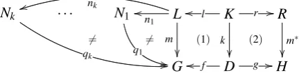
A DPO rule [EEPT06] consists of three graphs: left- and right-hand side (LandR) and inter-face graphK. Two morphisms1l:K→Landr:K→Rmodel the embedding ofK(containing the elements preserved by the rule) inLandR. Figure1shows a DPO direct derivation diagram. Square (1) is a pushout (i.e. Gis the union ofLandDthrough their common elements inK), modeling the deletion of the elements ofLnot inK, while pushout (2) adds the new elements, i.e. those present inRbut not inK. Figure1also illustrates the notion ofnegative application condition(NAC), as the association of a set of morphismsni:L→Ni, also notedNAC
− →n
←L, with a rule. A rule is applicable onGthrough a matchm:L→Gif there is no morphismqi:Ni→G,
withNiinNAC, commuting withm(i.e. qi◦ni=m). We exploit the partial order≤induced, up
to isomorphisms, by monomorphisms on the set of graphs, i.e.g1≤g2⇔ ∃m:g1,→g2.
Nk
qk
/
/
6=
. . . N1
q1 , , 6= L n1 o o nk t t m
(1)
K
(2)
l
o
o r //
k R m∗
Goo f D g //H
Figure 1: DPO Direct Derivation Diagram for rules with NAC.
Graph conditions allow the specification of models by forbidding the appearance of certain subgraphs, or by enforcing others to appear in given contexts. We use here a class of conditions Q similar to those in [HP09], where a condition over a graph Ais either of the formtrueor of the form∃(a,q), witha:A→Qa morphism fromAto some graphQandqa condition over Q. Conditions are also obtained by using the Boolean connectives¬and∨, and can be written in the form∀(a,q), equivalent to¬∃(a,¬q). We assume that all conditions in a setΘ⊂Qdiffer
for theamorphism, so that(a1,q1),(a2,q2)∈Θ⇒(A16'A2)∨(Q16'Q2). We will also use the short forms∃(Q)for∃(a: /0→Q,true) and@(Q) for¬∃(a: /0→Q,true). We restrict here to
positiveconditions of types∃(Q)or∀(a: /0→Q,q), noted∀(Q,q)withq=W
j∈Jqj:Q→Wja
disjunction of existential conditions. In this case, all the conditions of the form∃(Qi)∈Θcan
be collapsed into a single condition∃Q, withQthe colimit of allQion the diagram constructed
with all pairwise maximal common subgraphs. Simplenegativeconditions have the form@(Q).
Definition 1 Given a graphG, we say:
• A morphismm:X→Gsatisfies a conditionC, (m|=C),iff one of the following holds:
1. C=true.
2. C=∃(Y)andY ≤X.
3. C=∀(X,W
j∈Jqj:X→Wj)and∃mj:m(X)→Wjs.t.qj=mj◦mfor someqj.
4. C=@(Y)andY 6≤X.
5. C=C1∨C2andm|=C1orm|=C2.
• A graphG satisfies C(G|=C),iff one of the following holds:
1. C=true.
2. C=∃(Y)and there existsm:Y →Gs.t.m|=C.
3. C=∀(X,q)and for eachm:X→G,m|=C.
4. C=@(Y)and there is no morphismm:Y→G.
5. C=C1∨C2andG|=C1orG|=C2.
We say that a graphGtyped onT Gis amodelforΘ, notedG|=Θ, if for eachCi∈Θ,G|=Ci.
We assumeΘto be a consistent set of conditions, whose models are finite non-empty graphs; in
particular, simple graphs, with no two instances of the same edge type between two nodes. Transformation units control rule application through control words over rule names [KKS97]. Given: 1)G the class of typed graphs; 2)R the class of DPO rules with NACs onG; 3)=⇒
the DPO derivation relation; 4)E a class of graph expressions (here defined by type graphs and graph conditions), where thesemanticsof an expressioneis a subclasssem(e)⊂G; 5)W a class of control words over identifiers of rules inR exploiting single rules, the sequential construct ‘;’, the iteration constructw∗, withw∈W, the alternative choice ‘|’; atransformation unitis a constructTU = (e1,e2,P,imp,w), withe1,e2∈E initial and terminal graph class expressions, P⊂R a set of DPO rules, impa set of references to other, imported, units, whose rules can be used in the current one, and w∈W a control word enabling rules fromP, and units from imp, to be applied. TUs have a transactional behaviour, i.e. a unit succeedsiff it can be executed according to the control condition; it fails otherwise. The semantics of aTUis the setsem(TU) =
{(g1,g2)|g1∈sem(e1),g2∈sem(e2),g1
TU↓
=⇒g2}, where↓indicates successful termination.
4
A Running Example: Spider Diagrams and Spider Graphs
Spider Diagrams are a reasoning system based on Euler diagrams. Several variants exist, differ-ing in syntax and semantics [HMT+01]. We adopt a simplified version, based on Venn, rather than Euler, diagrams and omitting shading and strands. We first provide an indication of the con-crete syntax of the diagrams and an informal semantics. Then we propose a graph-based abstract model for them, calledSpider Graphs, which differs from the usual algebraic abstract models and is in fact slightly closer to the concrete model, even modelling spider’s feet.
LetC={C1, . . . ,Cn}be a collection of simple closed curves in the plane with finitely many
{int(Ci),ext(Ci)}, the interior ofCi or the exterior ofCi, for i∈ {1, . . . ,n}. If each of the 2n
possible zones ofC are non-empty and connected thenC is aVenn diagram (see [Rus97] for more details). Each zonez defines a unique partition of the setC, according to whether z is inside oroutside a curve. Two zones are calledtwinsif their inside and outside relations are switched for exactly one curve. In this paper, aSpider Diagramis a Venn diagram whose curves are labelled, together with extra syntax called spiders, which are trees whose vertices (called feet) are placed in unique zones. The set of zones containing a spider’s feet is called itshabitat. Special arcs, calledties, can be drawn between feet of different spiders in the same zone.
Intuitively, each curve represents a given set (indicated by the label) and each zone represents some set intersection. A spider indicates the existence of an element within the set determined by its habitat, whilst a tie between a pair of feet of different spiders within a zone indicates equality of elements, if both spiders represent an element in the set represented by the zone.
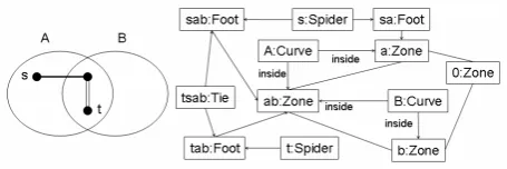
Figure 2 (left) shows an example of a Spider Diagram, with two curves {A,B} and four zones described by {({A},{B}), (/0,{A,B}), ({B},{A}), ({A,B},/0)}. Here, these zones are the four minimal region of the plane determined by the curves; for example, the zone described by({A},{B})is the regionint(A)∩ext(B)which is insideAbut outsideB. The habitat of spider sis the set of zones{({A},{B}),({A,B},/0)}, while that oftis the singleton{({A,B},/0)}. In-formally, the diagram semantics is: there are two setsAandB, there exists an element nameds inAand an element namedtinA∩B. Moreover, ifsis inA∩Bthens=t.
Figure 2: A Spider Diagram on the left, with the corresponding Spider Graph on the right.
We provide here an abstract graph-based model of a Spider Diagram, called aSpider Graph, not taking into account its concrete geometry. Since we are interested here only in syntactic aspects, we do not consider the labeling of the curves. We obtain the type graph of Figure3(left), where nodes represent the diagram elementsCurve,Foot,SpiderandZone, and edges represent relations between them. Atwinedge indicates that two zones are twins w.r.t. some curve and an inside/outsideedge indicates whether a curve contains/excludes a zone, respectively.
In Figure2(right) the Spider Graph associated with the Spider diagram on the left is shown. The names of the nodes show the correspondence with the objects in the diagram. We have two curve nodes in each possible relation with four zones2. For ease of reading, the zone nodes are given names consisting of a list of the lower case letters corresponding to the upper case letters used as names of the curves the zones are inside, and we useOfor the name of the node corresponding to the zone outside all curves in the diagram. Zone node pairsab andb, andO andaare twinned due to curveA, whilstabanda, andOandbare twinned due to curveB.
We now present the conditions completing the definition of the class of Spider Graphs.
Figure 3: The type graph (left) and negative conditions (right) for Spider Graphs.
ure 3 (right) shows a set of conditions of the form @Q, presented as forbidden graphs. They
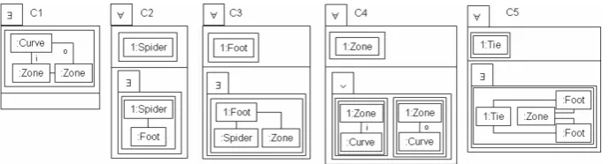
prevent duplication or inconsistency of information and state the uniqueness of relations be-tween zones and curves. Moreover, we assume the existence of all negative conditions forcing the graphs to be simple. We omit the direction of edges and their labels, when understood from the type graph, and use the abbreviations iando for the inside/outside case. The remaining conditions force the existence of a partition of the set of curves for all zones, and require suit-able contexts for zones and feet. We present them adopting a visual syntax where a condition
∃(a:A→Q,q)is represented by a box, separated into two parts by a horizontal line, with the top part containing a depiction of the morphismaand the bottom part containing a box depicting the conditionqonQ. An empty bottom box corresponds totrue. Each condition box has an exter-nal tab containing either quantifier information or the boolean connective∨,∧or¬. As we use conditions withA=/0, we only presentQand we do not repeatQin the depiction ofq. Numbers indicate identification in the morphisms, while not numbered nodes indicate a hidden existential quantification, as usual. Edges between identified nodes are also assumed to be identified in the morphisms. The class of Spider Graphs is the intersection of the languages defined by the type graph and the negative conditions of Figure3, and the positive conditions in Figures4to6.
Figure 4: Conditions on single elements.
Figure 5: Conditions on pairs of elements.
Figure 6: Conditions on existence and uniqueness of twins.
5
Condition preserving rules
We discuss the derivation of a condition-preserving transformation unitTUgt for the generation of an element of typet. The initial and terminal expressionse1ande2forTUgt define the class of graphs typed onT Gand satisfyingΘ. TUgt is associated with the execution of3r: /0← /0→ t
and is constructed so that given a graphG∈sem(e1), for G
TUt g↓
=⇒ H, (G,H)∈sem(TUgt), and G≤G+ t ≤H, where+indicates the pushout along the empty subgraph.
Note that in general G+ t 6|=Θ, but G+ t |=Θ0 for someΘ0⊂Θ. Hence, we admit that
some conditions may not be satisfied at intermediate steps of the unit application, and define an operationalclass in which to perform transformations. Graphs in this class satisfy a subset of the graph conditions and may be typed on someT G0 with additional types and edges w.r.t.T G. In particular, we use here the subsetΘ0 containing∃(Q)and all the conditions@(Qi)inΘ.
Before presenting the algorithm, we give its rationale. We only have to consider universal and negative existential conditions, as positive existential conditions cannot be violated by adding an element. However, adding t produces a graph G+ t which may not satisfyΘ in two ways: either it contains a forbidden subgraph, or it provides a new match for the premise of a universal condition, but it fails to satisfy the conclusion.
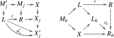
To solve the first problem, given4 a rule r:L→Rin TUgt (including r: /0→ t), for each condition@(X)∈Θ, the functiongenNAC(r,X)adds tor the set of NACs formed according to
the construction in Figure7(left). HereMjis a maximal common subgraph ofRandXandM0jis
a maximal common subgraph toMjandL, s.t. all the squares are pushouts. Hence,L→X0j←Xj
is the pushout forL←M0j→Xj, with the second morphism given by arrow composition. The set
of NACs contains all the morphismsn0j:L→X0j preserving the image ofLinXj. This prevents
the application ofron a match which could create the forbidden subgraphX(see [HHT96]).
M0j //
Mj / /X L
r //
@ @ @ R
L r //
n0jQQQQ((
Q Q Q Q Q 1 1
R //Xj
Mh > > } } } } A A
A Lh r
h
B B B
X0j X
? ? ~ ~ ~ // Rh
Figure 7: Constructing NAC (left) and incorporating available context (right).
To solve the second problem, given a (universal) conditionC=∀(Q,W
j∈Jqj:Q→Wj), s.t.
t ≤Q, the function genU niRules(C) produces the set of rules R(C) where each rule has the
formNAC(C)
− →
n
←Qr→C.jWj. TUgt will contain an alternative choice among these rules, produced
by the functionalt(R(C)). In order to prevent these rules from being applied indefinitely in case of iteration on the choice,NAC(C)contains a copy of eachWj so the same match is not reused
twice. Intuitively, these rules adjust the relations of the newly added element w.r.t. the contexts defined in their premises. However, several aspects have to be taken into account. For example, consider conditionsC2 in Figure 4 and suppose we want to add aSpider. Then, the derived rule will have to create aFoot(conditionC2), but this will require aZone(conditionC3), which will require aCurve(conditionC4), hence other additionalZones(conditionsC8 andC9), with several relations to other curves and zones (conditionsC10−C12). On the other hand, aZonefor aFootis already guaranteed to be present byC1, so that one can reuse existing context to satisfy this. To deal with such situations, given a ruler:L→Rand a contextX to be reused (more on this later), the functionreuseContext(r,X)produces a collection of rules of the formrh:Lh→Rh
according to the construction in Figure 7 (right). Here, L→Lh← X is the pushout along a
maximal common subgraphMhofLandX andX→Rh←Ris the pushout ofX←Mh→R.
In general, one wants to obtain aTUgt which, after applyingr: /0→ t toG, proceeds through the following abstract steps, so that context is progressively constructed for the next step.
1. define all edges between the added node and existing nodes ofGas required by conditions;
2. generate new nodes as required by the conditions;
3. generate all edges for the new nodes, as required by the conditions.
For example, when adding aCurve, one has to: 1) define relations between the new curve and existing zones; 2) create new zones, while defining relations with the new curve; 3a) establish relations between new zones and existing curves; 3b) establish relations between zones.
Two things have to be considered. In general, satisfaction of∀(Q,q)requires iterating through all possible matches forQ. However, whenQconsists of just one node, no iteration is necessary, and if Qis the graph t , the derived rule has to be applied only to the newly added node, as it is already satisfied for the nodes of type t which were in Goriginally. Hence, we extend T G to admit a special type of loop edge: the first rule is changed to r : /0→ t†, where t† designates a node with a marker loop. For a rule5r:L→R, the functionmark(r)produces a set Pr†={rh†:L†h→R†h|h: t →L}whereL†handR†hare obtained by adding the loop to the images h(L)andr◦h(L), the immersionsmh:L,→L†handm0h:R,→R
†
hpreserve such images, andr
†
h is
the unique morphism s.t.L†h r † h
→R†hm
0
h
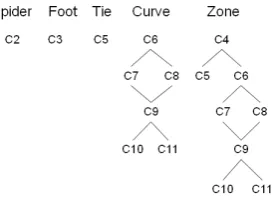
←Ris the pushout ofL†h←mh L→r R.TUgt will applyror rules fromPr†in different situations. The ruledelLoop: t†→ t will concludeTUgtdeleting the loop. Moreover, as in the examples above, some rules create new nodes if they cannot be provided by the context, and so conditions relative to the new nodes have to be satisfied. This potentially creates a situation in which an infinite recursion might start. To avoid this, we study the relations between types for which conditions are mutually recursive. In our example one such pair consists ofCurveandZone. Indeed, generating a curve implies the generation of a collection of zones, whilst the generation of a zone can imply the generation of a single curve and of the collection of zones related to the new curve: we need to distinguish between situations in which context, enriched with the new node which has started the process, has to be reused, and those in which a new node is needed to provide the correct context. Definition2provides the needed notation.
Definition 2 Lett∈VT be a type andQ(t)⊂Θthe set of conditions of the formOp(a:A→
Q,q), forOp∈ {∃,∀,@}s.t. t ≤Q(i.e. a node of typetappears inQ).{Q∃(t),Q∀(t),Q@(t)}is a partition ofQ(t)intoexistential6, universal and negative existentialconditions fort, respectively. VT∃ ={t| t ≤Q}is the set ofexistentially quantified types. A partial order≤C is induced on
Q∀(t)by(C1<CC2)⇔((A1<A2)∨((A1'A2)∧(Q1<Q2))). DAG(t) = (Q(t),≺,s,t)is the directed acyclic graph induced on Q(t), where (q1,q2)∈≺ ⇔q1<C q2 ∧ @qx s.t. q1 <Cqx,
qx<C q2. We callMin(t)the set of minimal models forΘ∪ {∃(Q+ t)}fort∈VT ⊂VT∃and
MIN(S)the set of minimal models forΘ∪St∈S⊂VT{∃(Q+ t)}.
For each conditionC∈Q∀(t)the rules ingenU niRules(C)will be applied in an order estab-lished by a functionvisit(DAG(t))which starts from initial nodes and proceeds from a join node only after all its incoming paths have been visited. In this way, progressively increasing contexts will have been produced, possibly providing new matches for the subsequent rules.
In order to follow the abstract steps discussed above, for a typetwe organize the rules derived fromQ∀(t)into layers: LAY ER1(t)contains rules which only add edges touching nodes of type t, LAY ER2(t)contains rules which add at least one node (of any type) in a non-empty context (and possibly edges of any type), whilstLAY ER3(t)contains rules which do not create nodes but add edges of any type, but with at least one edge between instances of some type other thant.
The sets Min(t) provide context which is certainly present if a unit for the addition of an element of typethas already been applied, whileQis guaranteed to be always present. Hence, reuseContextwill be invoked with parameterXequal toQorMin(t), depending on the situation.
5For each function operating on rules or types we overload the symbol to accept as argument sets. 6Note thatQ
Moreover, if an element of typet0 is created as a consequence of the generation of t, rules derived from visiting DAG(t0) have also to be applied, in the context provided by the already applied rules. Hence, we introduce a notion ofdominationand a predicatedominates(t,t0)≡
DAG(t0)≤DAG(t). Figure8shows the DAGs for the example introduced in Section 4. When adding a new zone, as we havedominates(Zone,Curve), the construction ofTUgcurveshould re-cursively be invoked. But then, rules fromQ∀(curve) would create new zones, thus requiring the invocation of rules fromQ∀(zone), etc. Hence, in the context of the construction ofTUgt if
DAG(t0)≤DAG(t), then the rules from the conditions inQ∀(t0)are generated used via reuseC-ontext, withX =MIN(t0), to take into account that the minimal context fort0can already exist. Also, a functioncreate(r)returns the set of types produced byr, i.e. inVT(R)\V(L).
Figure 8: The DAGs for Spider Graphs.
The resulting algorithmCreateGenUnit(t)populatesTUGt with rules derived fromQ∀(t), with added NACs to preserve conditions in Q@(t), and organizes them according to ordering and layering: rules are applied only when context for their application is ready.
AlgorithmCreateGenU nit(t:type):TU
initializeU NIT withrt†: /0→ t
† ;
foreachconditionC=∀(Q,q)∈Θdo{R(C) =genU niRules(C);} returnRecursiveGen(t,/0,f alse);
AlgorithmRecursiveGen(t:type,S:setOfTypes,inner:boolean):TU
path=visit(DAG(t));X=/0;aux=/0;
ifisEmpty(S)then{ift∈VT\VT∃then{X=Q;} }else{X=MIN(S);}
foreachconditionC=∀(Q,W
j∈Jqj:Q→Wj)∈pathdo{
foreachk∈ {1, . . . ,3}do{
foreacht0∈S{ifdominates(t,t0){aux=aux∪ {t0} } };
if!isEmpty(aux)then{X=MIN(aux)};single=/0;nosingle=/0;
foreachrulerC.h=NAC
− →n
←L→R∈R(C)∩LAY ERk(t)do{
if|V(L)|=1then{single=single∪ {rC.h} }else{nosingle=nosingle∪ {rC.h};};
if(inner)then{U NIT=concat(U NIT,alt(reuseContext(single,X))); U NIT=concat(U NIT,(alt(reuseContext(nosingle,X)))∗);
}else{U NIT=concat(U NIT,alt(mark(reuseContext(single,X)))); U NIT=concat(U NIT,(alt(mark(reuseContext(nosingle,X))))∗);}
U NIT=concat(U NIT,RecursiveGen(t0,S∪ {t},true));} } } } }; foreachruler:L→RinU NIT do{
foreachconditionC=@(X)∈Θdo{replacerwithgenNAC(r,X);} }; U NIT=concat(U NIT,delLoop);
returnU NIT
Theorem 1 A call CreateGenU nit(t,/0): 1) terminates, and 2) produces a correct unit TUgt s.t.
given a graph G typed on T G s.t. G|=Θ,∀H s.t. GTU t g↓
=⇒H, we have H|=Θ∪ {∃(G+ t)}.
Proof. (Sketch) 1) The first nested loop performs a finite number of iterations on conditions, layers and rules. The recursion onrecursiveGen terminates since the setSincreases in size on each call. The final iteration to add NACs occurs on a finite number of conditions and rules.
2) If the first rule is applicable, then the application ofTUG(t)terminates on each finite graph
Gs.t.G|=Θ. Indeed, the NACs prevent repeated applications of a rule on identical matches, and
even if new matches can be created, the layering prevents infinite repetition of the execution of a rule. Moreover, the application ofreuseContextavoids arbitrary generation of new elements. If a graphHis obtained, thenH|=∃(G+ t), as only increasing rules have been applied. Suppose now thatH6|=Θ. Then either: 1)H6|=Cifor someCiin someQ@(t), but this is impossible as this
is prevented by the use ofgenNAC; or 2)H6|=∃Q, but this is impossible asQ≤G≤G+ t ≤H; or 3)H6|=Ci for someCiin someQ∀(t), but this is impossible as all the rules are derived from someQ∀(t)and all matches for their premises have been considered.
6
Application to Spider Diagrams
Contrasted to algorithmic definitions of inference figures for Spider Diagrams, the proposed approach allows the modeling both of syntactically correct Spider Diagram and of an operational system, admitting intermediary-type diagrams with some syntactic constraints relaxed.
We now apply the constructions in Section5. Firstly, considering the addition of aCurve, we have conditions Q∃(Curve) ={C1}, Q∀(Curve) ={(C7),(C8,C9),(C10),(C11,C12)}, where we have abused notation for universal conditions to indicate their ordering according to≤Q; e.g.
the premise ofC7 is included in the premise of bothC8 andC9. The layers associated to the type Curveare as follows. LAY ER1(Curve)contains rules generated fromC7,C11,C12 and from the first two graphs in the bottom box ofC10 since these only add edges incident with nodes of typeCurve. LAY ER2(Curve)contains rules generated fromC8,C9 which addZonenodes, whilstLAY ER3(Curve)consists of the rule generated from the last graph in the bottom box in C10 which adds an edge between nodes of typeZone.
Note that depending on which iteration of the rules derived fromC8 orC9 is applied first, the other iteration will be performed vacuously. The same thing happens forC11 andC12.
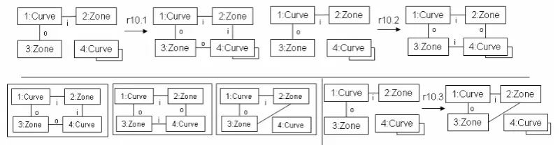
Figure9shows a version of the rules derived from conditionC10, with one choice of marking. Each possible conclusion of the rules fromC10 give rise to a NAC, preventing re-application of the rule to the same match, and the set of three NACs (these define thenj morphisms in the
construction provided earlier) is presented together at the bottom left of the figure.
algorithm produces a transformation unit of the form:
TU(addCurve)=r†curve;(r7.1†|r7.2†)∗;(r10.1†|r10.2†)∗;(r11†)∗;(r12†)∗;(r8†);(r9†)∗;
(r4.1|r4.2)∗;r6∗;(r7.1|r7.2)∗;(r10.1|r10.2|r10.3)∗;r11∗;r12∗;r10.3∗ The iterations on rules from r4.i to r12 in the second row derive from the fact that someZone is created in the previous rules, so that the second top-level loop must be started, reusing context to prevent the creation of new curves.
The analogous construction for the typeZoneis based on the following specificationsQ∃(Zone)
= {C1}, Q∀(Zone) ={(C4),(C6,C7),(C8,C9),(C10),(C11,C12)}. LAY ER1(Zone) contains the rules generated fromC7,C10,C11, whileLAY ER2(Zone)contains the rules generated from C8 andC9. In this case, the unit will first define the relations of the new zone with the existing curves, according to the rule fromC4, then create a required new curve (as the context does not provide one to satisfyC6). After the iteration of the rule forC7, the context again will not be sufficient for the application of the rules fromC8 andC9. Finally, the rules fromC10,C11 and C12 will adjust the relations with the newly created curves and among all zones.
Figure 9: A marked version of the 3 rules derived from condition C10 and the non-marked NAC.
For a Spider, we have Q∃(Spider) = /0, Q∀(Spider) ={(C2)}, generating a rule in layer 2. While the creation of aSpiderrequires the creation of aFoot, theZonewill be taken from the context, due to its presence in Q, so that it has been incorporated by the application of reuseContext. Insertion of aFootwill instead require the creation of a newSpider, if none exists, or its reuse if one had already been created. However, such a creation will fail if the spider has already a foot in each existing zone.
In a similar way, a unit for the deletion of a curve would first remove the twin edges between zones attached to the marked curve, then all edges from all other curves to these zones, then all zones attached with aninsideoroutsideedge to the curve to be removed, then all remaining connections from the marked Curve node to be deleted, and finally the marked node itself. Removal of a spider would be preceded by removal of all its feet and their attachments to zones. The construction of such units is beyond the scope of this paper.
7
Conclusions
As a result, membership in the model language is ensured before and after the application of the unit, but not necessarily throughout the unit. The methodology exploits a rule layering approach, and rules are generated from graph conditions taking into account the rule application context.
The automatic production of the rules needed to reassemble a syntactically correct diagram simplifies the specification of diagrammatic inference rules and supports therefore the develop-ment and comparison of syntactic and semantic variations of the systems. Future work will define a similar algorithm for deleting rules, adding preparatory rules for performing a final deletion.
Of course, semantic considerations play a greater role than simple syntactic constraints. How-ever, the constructed rules may provide a basis to be extended with additional context and con-sequences. For example, the specification of a transformation via pre- and post-conditions can be used to integrate syntactic rules with specific side effects. In this sense, this construction provides more flexibility to modelers, who can define the language through conditions, the main goal of a transformation and the desired side effects in an independent manner. This removes the need to consider complex interplays between rules and constraints, as in approaches which derive amalgamated rules which have to achieve a global effect with a single specification.
We notice that most transformations involve redirection of associations from one element to another, or changing the context for an element. The construction presented in the paper can be adapted to defineaccumulatorsanddistributorsof associations, which would collect all edges to be redirected, while deleting or constructing elements. Hence, such redirections might be taken as primitive constructs. The approach has been presented only for typed graphs. Extensions to graphs with inheritance and with attributes have to be explored, in particular for the case where identifiers are used to describe the associations of an element with others.
This would be useful also in other domains. For instance, model refactoring often involves the elimination of elements, or the creation of suitable contexts for their insertion. One example is the elimination of a composite state in a Statechart which requires the elimination of all of its internal states. Then, given a set of conditions stating that each state must be contained within a composite state, the construction in Section5could be applied to generate transformation units to be recursively invoked to visit the nesting tree. Another refactoring example is that of moving a method. This requires placing it in a different class and redirecting all its invocations, as well as the messages which may originate from its invocation, to its new location. Our construction can thus be used to manage the identification of the arcs related to such a method.
Acknowledgements: Partially funded by UK EPSRC grant EP/E011160: Visualisation with Euler Diagrams.
Bibliography
[BGL08] P. Bottoni, E. Guerra, J. de Lara. Enforced generative patterns for the specification of the syntax and semantics of visual languages.JVLC19(4):429–455, 2008.
[EEHP06] H. Ehrig, K. Ehrig, A. Habel, K.-H. Pennemann. Theory of Constraints and Ap-plication Conditions: From Graphs to High-Level Structures. Fundam. Inform. 74(1):135–166, 2006.
[EEPT06] H. Ehrig, K. Ehrig, U. Prange, G. Taentzer. Fundamentals of Algebraic Graph Transformation. Springer, 2006.
[EKTW06] K. Ehrig, J. M. K¨uster, G. Taentzer, J. Winkelmann. Generating Instance Models from Meta Models. InProc. FMOODS 2006. LNCS 4037, pp. 156–170. Springer, 2006.
[GMT99] M. Goedicke, T. Meyer, G. Taentzer. ViewPoint-oriented software development by distributed graph transformation: towards a basis for living with inconsistencies. In Proc. IEEE Requirements Engineering, 1999. Pp. 92–99. 1999.
[HHT96] A. Habel, R. Heckel, G. Taentzer. Graph Grammars with Negative Application Con-ditions.Fundam. Inform.26(3/4):287–313, 1996.
[HHT02] J. H. Hausmann, R. Heckel, G. Taentzer. Detection of conflicting functional require-ments in a use case-driven approach: a static analysis technique based on graph transformation. InProc. ICSE ’02. Pp. 105–115. ACM Press, 2002.
[HMT+01] J. Howse, F. Molina, J. Taylor, S. Kent, J. Gil. Spider Diagrams: A Diagrammatic Reasoning System.JVLC12(3):299–324, 2001.
[HP09] A. Habel, K.-H. Pennemann. Correctness of high-level transformation systems rel-ative to nested conditions.Math. Struc. in Comp. Sc.19(2):245–296, 2009.
[KKS97] H.-J. Kreowski, S. Kuske, A. Sch¨urr. Nested graph transformation units.Int. J. on SEKE7(4):479–502, 1997.
[MSW00] M. M¨unch, A. Sch¨urr, A. J. Winter. Integrity Constraints in the Multi-paradigm Language PROGRES. InSelected Papers from TAGT’98. LNCS 1764, pp. 338–351. Springer, 2000.
[OEP08] F. Orejas, H. Ehrig, U. Prange. A Logic of Graph Constraints. InProc. FASE 2008. LNCS 4961, pp. 179–198. Springer, 2008.
[Pen09] K.-H. Pennemann.Development of Correct Graph Transformation Systems. Ph.d thesis, Carl von Ossietzky Universit¨at - Oldenburg, 2009.
[Ren04] A. Rensink. Representing First-Order Logic Using Graphs. In Proc. ICGT. LNCS 3256, pp. 319–335. Springer, 2004.
[RK09] A. Rensink, J.-H. Kuperus. Repotting the Geraniums: On Nested Graph Transfor-mation Rules.ECEASST - Proc. GT-VMT 200918, 2009.