utility models, or trademarks.
The absence of any such references does not indicate that a product is patent-free.
te: 2
1.02.
13
Table of Contents
Control III Programming in C (small PLC)
1
Symbol Catalog ... 7
2
General ... 8
2.1 Product information ... 8 2.2 Introduction ... 83
Safety... 9
3.1 Intended use ... 93.2 General safety information ... 9
3.3 Disposal ... 9
4
Programming Control III ... 10
4.1 Overview ... 10
4.1.1 ASi Data Exchange ... 12
4.1.2 AS-i Read IDI ... 14
4.1.3 AS-i Write ODI ... 14
4.1.4 AS-i Read ODI ... 14
4.1.5 AS-i Write Permanent Parameter ... 15
4.1.6 AS-i Read Permanent Parameter ... 15
4.1.7 AS-i Send Parameter ... 15
4.1.8 AS-i Read PI ... 16
4.1.9 AS-i Store PI ... 16
4.1.10 AS-i Read Duplicate Address List ... 16
4.1.11 AS-i Read Fault Detector ... 17
4.1.12 AS-i Write PCD ... 17
4.1.13 AS-i Read PCD ... 17
4.1.14 AS-i Store CDI ... 18
4.1.15 AS-i Read CDI ... 18
4.1.16 AS-i Write Extended ID1 ... 18
4.1.17 AS-i Write LPS ... 19
4.1.18 AS-i Read LPS ... 20
4.1.19 AS-i Read LAS ... 20
4.1.20 AS-i Read LDS ... 21
4.1.21 AS-i Read LCS ... 21
4.1.22 AS-i Write LOS ... 21
4.1.23 AS-i Read LOS ... 22
4.1.24 AS-i Read LPF ... 22
4.1.25 AS-i Read Ec Flags ... 22
4.1.26 AS-i set Config Mode ... 23
4.1.27 AS-i Write Hi Flags ... 23
4.1.27.1 AS-i Read Hi-Flags ... 23
4.1.28 AS-i Address Slave ... 24
4.1.30 AS-i Read All Config ...24
4.1.31 AS-i Write All Config ...25
4.1.32 AS-i read Error Counter ...25
4.1.33 AS-i Mail Box ...25
4.1.34 AS-i Write 16-bit ODI ...26
4.1.35 AS-i Read 16Bit ODI ...26
4.1.36 AS-i Read 16Bit IDI ...27
4.1.37 AS-i Read Ctrl Acc ODI ...27
4.1.38 AS-i Write Ctrl Acc ODI ...28
4.1.39 AS-i Read Ctrl Acc AODI ...28
4.1.40 AS-i Write Ctrl Acc AODI ...29
4.1.41 Ctrl Init Timer ...29
4.1.42 Ctrl Delay ...29
4.1.43 Ctrl Init wgd ...29
4.1.44 Ctrl Trigger wdg ...30
4.1.45 Ctrl Eval Cycle time ...30
4.1.46 Ctrl Read Parameter ...30 4.1.47 Ctrl Write Parameter ...30 4.1.48 Ctrl Read Flags ...31 4.1.49 Ctrl Write Flags ...31 4.1.50 Crtl Read Key ...31 4.1.51 Ctrl printf ...31 4.1.52 Ctrl Breakpoint ...31 4.1.53 Ctrl Display ...32
5
Getting Started ... 33
5.1 Installing Eclipse Control III ... 33
5.2 Enabling Control III ... 33
6
Using Eclipse... 34
6.1 Starting ... 34
6.2 Eclipse overview ... 34
6.2.1 The Project Explorer ...34
6.2.2 Toolbar ...35 6.2.2.1 Compiler ...35 6.2.2.2 Debugging ...35 6.2.2.3 Configuration tools ...35 6.2.3 Editor ...36 6.2.4 Console ...36 6.3 File information ... 37
6.4 Setting the port ... 38
6.5 Creating a new project ... 38
6.6 A sample project ... 39
6.6.1 The C-code ...39
6.6.2 Compiling ...42
6.6.3 Downloading ...42
6.6.4 Starting Control III ...42
te: 2
1.02.
13
6.7.2 Debugger overview ... 43
6.7.2.1 The Control Panel ... 44
6.7.2.2 Tasks ... 44
6.7.2.3 Debugger Overview ... 44
6.7.2.4 Code overview ... 45
6.7.2.5 Disassembly ... 45
6.7.2.6 Console ... 45
6.7.3 Start the Debugger ... 45
6.7.4 Example ... 46
6.7.4.1 Starting the Debugger ... 50
6.7.4.2 Using the Debugger ... 51
7
Technical Data ... 53
7.1 Overview ... 53
7.2 Flags ... 53
7.3 Non-volatile parameters ... 53
7.4 Access rights to the output data area ... 54
8
Error Messages... 55
8.1 error: control not activated! ... 55
8.2 error: wrong control version ... 55
8.3 Launching problem ... 55
8.4 No or an incorrect cycle time is displayed. ... 56
8.5 The gateway doesn’t stop at a breakpoint. ... 56
8.6 The program always goes to the same breakpoint. ... 56
List of Figures
Fig. 1. Eclipse Control III start window ...34
Fig. 2. Eclipse settings.mak ...38
Fig. 3. New Control III project ...39
Fig. 4. Debug Configuration... ...46
Fig. 5. Marking a breakpoint in the program code ...50
Fig. 6. First breakpoint in Debug-mode ...51
Fig. 7. Second breakpoint in Debug-mode ...51
Fig. 8. Flag area ...53
Fig. 9. Non-volatile parameters ...54
Fig. 10. Access rights for the output data area ...54
Fig. 11. error: control not activated ...55
Fig. 12. error: wrong control version! ...55
te: 2
1.02.
2013
1.
Symbol Catalog
Information!
2.
General
2.1 Product information
Control III performs all the tasks of a powerful small PLC and allows you to pre-process all sensor and actuator information.
2.2 Introduction
Control III, the AS-i Master PLC functionality integrated into the AS-i Master works together with standard AS-i I/O modules to form a small PLC with up to 248 in- and outputs per AS-i circuit, or up to 496 I/Os in a dual master. Standard C is used for all programming tasks of the small PLC.
Use of Control III in the gateways makes it possible to preprocess the sensor/ac-tuator information. Typical applications include preprocessing of data as well as rapid execution of time-critical operations directly in the gateway.
The program for Control III is created on a standard PC and then uploaded to the AS-i master. A specially created Eclipse version (IDE) is provided as the pro-gramming tool. This includes all the tools needed for creating and testing the Control III program.
Control III is written in the widely used and very powerful “C” programming lan-guage. Various library functions serve to assist you and make programming ea-sier.
The Control III program is loaded through one of the ports on the gateway and stored non-volatile in flash memory.
te: 2
1.02.
2013
3
Safety
3.1 Intended use
3.2 General safety information
3.3 Disposal
Warning!
This symbol warns of a possible danger. The protection of operating personnel and the system against possible danger is not guaranteed if the control interface unit is not operated in accordance to its intended use.
Warning!
Safety and correct functioning of the device cannot be guaranteed if any operation other than described in this operation manual is performed. Connecting the equipment and conducting any maintenance work under power must exclusively be performed by appropriately qualified personnel. In case a failure cannot be eliminated, the device must be taken out of operation and inadvertently operation must be prevented. Repair work must be performed by the manufacturer only. Additions or modifications to the equipment are not permitted and will void the warranty.
Information!
The operator is responsible for the observation of local safety standards.
Information!
Electronic waste is hazardous waste. Please comply with all local ordinances when disposing this product!
4
Programming Control III
Programming of Control III is based on the widely-used and highly modular pro-gramming language ‘C’. To create a Control III program, all the tasks that the gateway must assume must be written in ‘C’ and loaded into the gateway. To program with Control III, the header file ‘control.h’ contains a series of library functions which can be used for running certain master functions. These func-tions are listed and explained in the following.
4.1 Overview
AASiDataExchange AS-i Data Exchange is used for exchanging AS-i data and reads the ‘execution control’ flags.
AASiReadIDI Reads the slave input data and the ‘execution cont-rol’ flags.
AASiWriteODI Writes the slave output data.
AASiReadODI Reads the output data from the AS-i master.
AASiWritePP Writes the permanent parameters of a slave in the master.
AASiReadPP Reads the permanent parameters of a slave in the master.
AASiSendParameter Sends the parameters to a slave.
AASiReadPI Reads the current parameters of a slave
AASiStorePI Stores the current slave parameters as permanent parameters.
AASiReadDuplicateAdrList Reads the list of all duplicate addresses.
AASiReadFaultDetector Reads overvoltage, noise, EFLT and duplicate addresses.
AASiWritePCD Writes the projected configuration of a slave.
AASiReadPCD Reads the projected configuration of a slave.
AASiStoreCDI Stores the current configuration as a permanent configuration.
AASiReadCDI Reads the current configuration of a slave.
AASiWriteExtID1 Writes the extended ID code 1 of Slave 0.
AASiWriteLPS Writes the projected slave.
AASiReadLPS Reads the projected slaves.
AASiReadLAS Reads the activated slaves
AASiReadLDS Reads the detected slaves.
AASiReadLCS Reads all defective slaves.
te: 2
1.02.
2013
AASiReadEcFlags Reads the ’execution control’ flags
AASiSetConfigMode Sets the AS-i master to Configuration mode or to protected operating mode.
AASiWriteHiFlags Writes the Host-Interface-Flags of the AS-i Master.
AASiReadHiFlags Reads the Host-Interface-Flags of the AS-i Master.
AASiAddressSlave Changes the address of a slave.
AASiExecuteCommand AS-Interface command to be sent directly.
AASiReadAllConfig Reads all configuration data (e.g. LPS, PP[ ] and PCD [ ]) for all connected slaves.
AASiWriteAllConfig Writes all configuration data (e.g. LPS, PP[ ] and PCD [ ]) for all connected slaves.
AASiReadErrorCounters Reads the Slave-Error-Counter
AASiMailbox Generic Mailbox function.
AASiWrite16BitODI Writes four channels of 16-bit ODI to an AS-i-Slave having e.g. Analog-Slave profile 7.3 or 7.4.
AASiRead16BitODI Reads four channels of 16-bit ODI to an AS-i-Slave having e.g. Analog-Slave profile 7.3 or 7.4.
AASiRead16BitIDI Reads four 16-bit IDI channels of an AS-i slave having e.g. Analog-Slave profile 7.3 or 7.4.
AASiReadCtrlAccODI Reads the Control III authorization in order to change output data.
AASiWriteCtrlAccODI Writes the Control III authorizations of the slave in order to change output data.
AASiReadCtrlAccAODI Reads the Control III authorization in order to change analog output data.
AASiWriteCtrlAccAODI Writes the Control III authorizations of the slave in order to change analog output data.
CCtrlInitTimer Initialization of a timer function
CCtrlDelay Delay in ms
CCtrlInitWdg Initialization of the Control III watchdog
CCtrlTriggerWdg Trigger Control III Watchdog.
CCtrlEvalCycletime Evaluates the Control lII cycle time.
CCtrlReadParameter Reads Control NV-Parameter.
CCtrlWriteParameter Writes Control NV-Parameter.
CCtrlReadFlags Reads Control-Flags.
CCtrlWriteFlags Writes Control-Flags.
CCtrlReadkey Reads user-defined unique control key.
CCtrlPrintf Printf function
CCtrlBreakpoint Initializes the Debugger
4.1.1 ASi Data Exchange
AS-i Data Exchange is used for exchanging AS-i data between the master and the application and reads the ‘execution control’ flags.
int (*AASiDataExchange) (unsigned char Circuit, AASiProcessData ODI, AASiProcessData IDI, AASiEcFlags *EcFlags);
Parameter:
Circuit: AS-i Master circuit
ODI: 32 bytes output data Return:
IDI: 32 bytes input data
EcFlags: Execution control flags (2 Bytes) of the AS-i Master.
AS-i circuit 1 / 2 : Input data image IDI
Bit 7 6 5 4 3 2 1 0 Bit 7 6 5 4 3 2 1 0
Byte D3 D2 D1 D0 D3 D2 D1 D0 Byte D3 D2 D1 D0 D3 D2 D1 D0 0 Slave 1/1A Slave 0/0A 1 Slave 3/3A Slave 2/2A 2 Slave 5/5A Slave 4/4A 3 Slave 7/7A Slave 6/6A 4 Slave 9/9A Slave 8/8A 5 Slave 11/11A Slave 10/10A 6 Slave 13/13A Slave 12/12A 7 Slave 15/15A Slave 14/14A 8 Slave 17/17A Slave 16/16A 9 Slave 19/19A Slave 18/18A 10 Slave 21/21A Slave 20/20A 11 Slave 23/23A Slave 22/22A 12 Slave 25/25A Slave 24/24A 13 Slave 27/27A Slave 26/26A 14 Slave 29/29A Slave 28/28A 15 Slave 31/31A Slave 30/30A 16 Slave 1/1B Slave 0/0B 17 Slave 3/3B Slave 2/2B 18 Slave 5/5B Slave 4/4B 19 Slave 7/7B Slave 6/6B 20 Slave 9/9B Slave 8/8B 21 Slave 11/11B Slave 10/10B 22 Slave 13/13B Slave 12/12B 23 Slave 15/15B Slave 14/14B 24 Slave 17/17B Slave 16/16B 25 Slave 19/19B Slave 18/18B 26 Slave 21/21B Slave 20/20B 27 Slave 23/23B Slave 22/22B 28 Slave 25/25B Slave 24/24B 29 Slave 27/27B Slave 26/26B 30 Slave 29/29B Slave 28/28B 31 Slave 31/31B Slave 30/30B
te: 2
1.02.
2013
AS-i circuit 1 / 2 : Output data image ODI
Bit 7 6 5 4 3 2 1 0 Bit 7 6 5 4 3 2 1 0
Byte D3 D2 D1 D0 D3 D2 D1 D0 Byte D3 D2 D1 D0 D3 D2 D1 D0 0 Slave 1/1A Slave 0/0A 1 Slave 3/3A Slave 2/2A 2 Slave 5/5A Slave 4/4A 3 Slave 7/7A Slave 6/6A 4 Slave 9/9A Slave 8/8A 5 Slave 11/11A Slave 10/10A 6 Slave 13/13A Slave 12/12A 7 Slave 15/15A Slave 14/14A 8 Slave 17/17A Slave 16/16A 9 Slave 19/19A Slave 18/18A 10 Slave 21/21A Slave 20/20A 11 Slave 23/23A Slave 22/22A 12 Slave 25/25A Slave 24/24A 13 Slave 27/27A Slave 26/26A 14 Slave 29/29A Slave 28/28A 15 Slave 31/31A Slave 30/30A 16 Slave 1/1B Slave 0/0B 17 Slave 3/3B Slave 2/2B 18 Slave 5/5B Slave 4/4B 19 Slave 7/7B Slave 6/6B 20 Slave 9/9B Slave 8/8B 21 Slave 11/11B Slave 10/10B 22 Slave 13/13B Slave 12/12B 23 Slave 15/15B Slave 14/14B 24 Slave 17/17B Slave 16/16B 25 Slave 19/19B Slave 18/18B 26 Slave 21/21B Slave 20/20B 27 Slave 23/23B Slave 22/22B 28 Slave 25/25B Slave 24/24B 29 Slave 27/27B Slave 26/26B 30 Slave 29/29B Slave 28/28B 31 Slave 31/31B Slave 30/30B
4.1.2 AS-i Read IDI
AS-i Read IDI reads the input data from slaves and the execution control flags.
int (*AASiReadIDI) (unsigned char Circuit, AASiProcessData IDI, AASiSlaveAddr First, unsigned char Amount, AASiEcFlags *EcFlags);
4.1.3 AS-i Write ODI
AS-i Write ODI writes the output data from slaves.
int (*AASiWriteODI) (unsigned char Circuit, AASiProcessData ODI, AASiSlaveAddr First, unsigned char Amount);
Each slave uses 4 bits (nibble) of a byte. Unused bytes are set to null. Return: —
4.1.4 AS-i Read ODI
AS-i Read ODI reads the output data from the AS-i Master.
int (*AASiReadODI) (unsigned char Circuit, AASiProcessData ODI);
Parameter:
Circuit: AS-i Master circuit
First: Index of the first slaves
Amount: Number of slaves to read
Return:
IDI: 32 bytes input data
Each slave uses 4 bits (nibble) of a byte. Unused bytes are set to null
EcFlags: Execution control flags (2 Bytes) of the AS-i master
Parameter:
Circuit: AS-i Master circuit
ODI: 32 bytes output data
First: Index of the first slave
Amount: Number of slaves to be written
Parameter:
Circuit AS-i Master circuit
Return:
ODI: 32 bytes output data
te: 2
1.02.
2013
4.1.5 AS-i Write Permanent Parameter
AS-i Write Permanent Parameter writes the permanent parameters of a slave in the Master.
int (*AASiWritePP) (unsigned char Circuit, AASiSlaveAddr Address, AASiSlaveData PP);
4.1.6 AS-i Read Permanent Parameter
AS-i Read Permanent Parameter reads the permanent parameters of a slave in the Master.
int (*AASiReadPP) (unsigned char Circuit, AASiSlaveAddr Address, AASiSlaveData *PP);
4.1.7 AS-i Send Parameter
AS-i Send Parameter sends the parameters to a slave.
int (*AASiSendParameter) (unsigned char Circuit, AASiSlaveAddr Address, AASiSlaveData PI, AASiSlaveData *Return);
Parameter:
Circuit: AS-i Master circuit
Address: Slave address
PP: Permanent Parameters (low Nibble)
Return: —
Parameter
Circuit: AS-i Master circuit
Address: Slave address Return:
PP: Permanent parameters (low nibble)
Parameter:
Circuit: AS-i Master circuit
Address: Slave address
PI: Parameters to be sent (low Nibble)
Return:
4.1.8 AS-i Read PI
AS-i Read PI reads the current parameters of a slave.
int (*AASiReadPI) (unsigned char Circuit, AASiSlaveAddr Address, AASiSlaveData *PI);
4.1.9 AS-i Store PI
AS-i Store PI stores the current slave parameters as permanent parameters.
int (*AASiStorePI) (unsigned char Circuit);
4.1.10 AS-i Read Duplicate Address List
AS-i Read Duplicate Address List reads the list of all duplicate addresses.
int (*AASiReadDuplicateAdrList) (unsigned char Circuit, AASiSlaveList, *DpAdrList);
Parameter:
Circuit: AS-i Master circuit
Address: Slave address
Return:
PI: Parameters to be sent (low Nibble)
Parameter:
Circuit: AS-i Master circuit
Address: Slave address
Return: —
Parameter:
Circuit: AS-i Master circuit Return:
te: 2
1.02.
2013
4.1.11 AS-i Read Fault Detector
AS-i Read Fault Detector reads overvoltage, noise, EFLT and duplicate addres-ses.
int (*AASiReadFaultDetector) (unsigned char Circuit, unsigned char *pucFaultDetectorActiv,
unsigned char *pucFaultDetectorHistoric);
4.1.12 AS-i Write PCD
AS-i Write PCD writes the projected configuration of a slave.
int (*AASiWritePCD) (unsigned char Circuit, AASiSlaveAddr Address, AASiConfigData PCD);
4.1.13 AS-i Read PCD
AS-i Read PCD reads the projected configuration of a slave.
int (*AASiReadPCD) (unsigned char Circuit, AASiSlaveAddr Address, AASiConfigData *PCD);
Parameter:
Circuit: AS-i Master circuit
Return:
PucFaultDetectorActiv: Active fault detector
PucFaultDetectorHistoric: Historic fault detector
Parameter:
Circuit: AS-i Master circuit
Address: Slave address Return:
PCD: Projected slave configuration to be written
Bit 7 6 5 4 3 2 1 0
Byte D3 D2 D1 D0 D3 D2 D1 D0
0 Slave ID I/O Configuration
1 Extended ID2 Extended ID1
Tab. 4-3. PCD configuration
Parameter:
Circuit: AS-i Master circuit
Address: Slave address
Return:
4.1.14 AS-i Store CDI
AS-i Store CDI stores the current configuration as a permanent configuration.
int (*AASiStoreCDI) (unsigned char Circuit);
4.1.15 AS-i Read CDI
AS-i Read CDI reads the current configuration of a slave.
int (*AASiReadCDI) (unsigned char Circuit, AASiSlaveAddr Address, AASiConfigData *CDI);
4.1.16 AS-i Write Extended ID1
AS-i Write Extended ID1 writes the extended ID-Code 1 von Slave 0.
int (*AASiWriteExtID1) (unsigned char Circuit, AASiSlaveData ID1);
Parameter:
Circuit: AS-i Master circuit
Parameter:
Circuit: AS-i Master circuit
Address: Slave address Return:
CDI: Slave configuration
Bit 7 6 5 4 3 2 1 0
Byte D3 D2 D1 D0 D3 D2 D1 D0
0 Slave ID I/O Configuration
1 Extended ID2 Extended ID1
Tab. 4-4. CDI configuration
Parameter:
Circuit: AS-i Master circuit
Address: Slave address
ID1: Extended ID-Code 1 Return:
Special error codes which describe the reason for the faulty transmis-sion.
te: 2
1.02.
2013
4.1.17 AS-i Write LPS
AS-i Write LPS writes the projected slaves.
int (*AASiWriteLPS) (unsigned char Circuit, AASiSlaveList LPS);
Each bit in the LPS corresponds to a slave as follows:
The slave is projected if the bit is set. Parameter:
Circuit: AS-i Master circuit
LPS: 8-byte Slave list
Bit Slave Bit Slave Bit Slave Bit Slave
0 Slave 0/0A cannot be set!
16 Slave 16/16A 32 Slave 0/0B cannot be set!
48 Slave 16/16B
1 Slave 1/1A 17 Slave 17/17A 33 Slave 1/1B 49 Slave 17/17B 2 Slave 2/2A 18 Slave 18/18A 34 Slave 2/2B 50 Slave 18/18B 3 Slave 3/3A 19 Slave 19/19A 35 Slave 3/3B 51 Slave 19/19B 4 Slave 4/4A 20 Slave 20/20A 36 Slave 4/4B 52 Slave 20/20B 5 Slave 5/5A 21 Slave 21/21A 37 Slave 5/5B 53 Slave 21/21B 6 Slave 6/6A 22 Slave 22/22A 38 Slave 6/6B 54 Slave 22/22B 7 Slave 7/7A 23 Slave 23/23A 39 Slave 7/7B 55 Slave 23/23B 8 Slave 8/8A 24 Slave 24/24A 40 Slave 8/8B 56 Slave 24/24B 9 Slave 9/9A 25 Slave 25/25A 41 Slave 9/9B 57 Slave 25/25B 10 Slave 10/10A 26 Slave 26/26A 42 Slave 10/10B 58 Slave 26/26B 11 Slave 11/11A 27 Slave 27/27A 43 Slave 11/11B 59 Slave 27/27B 12 Slave 12/12A 28 Slave 28/28A 44 Slave 12/12B 60 Slave 28/28B 13 Slave 13/13A 29 Slave 29/29A 45 Slave 13/13B 61 Slave 29/29B 14 Slave 14/14A 30 Slave 30/30A 46 Slave 14/14B 62 Slave 30/30B 15 Slave 15/15A 31 Slave 31/31A 47 Slave 15/15B 63 Slave 31/31B
4.1.18 AS-i Read LPS
AS-i Read LPS reads the projected slaves.
int (*AASiReadLPS) (unsigned char Circuit, AASiSlaveList *LPS);
The slave is projected if the bit is set. 4.1.19 AS-i Read LAS
AS-i Read LAS reads the activated slaves.
int (*AASiReadLAS) (unsigned char Circuit, AASiSlaveList *LAS);
Each bit in the LAS corresponds to a slave. Parameter:
Circuit: AS-i Master circuit Return:
LPS: 8-byte slave list (see Tab. <LPS>)
Parameter:
Circuit: AS-i Master circuit
LAS: 8-byte slave list
Bit Slave Bit Slave Bit Slave Bit Slave
0 Slave 0/0A 16 Slave 16/16A 32 Slave 0/0B 48 Slave 16/16B 1 Slave 1/1A 17 Slave 17/17A 33 Slave 1/1B 49 Slave 17/17B 2 Slave 2/2A 18 Slave 18/18A 34 Slave 2/2B 50 Slave 18/18B 3 Slave 3/3A 19 Slave 19/19A 35 Slave 3/3B 51 Slave 19/19B 4 Slave 4/4A 20 Slave 20/20A 36 Slave 4/4B 52 Slave 20/20B 5 Slave 5/5A 21 Slave 21/21A 37 Slave 5/5B 53 Slave 21/21B 6 Slave 6/6A 22 Slave 22/22A 38 Slave 6/6B 54 Slave 22/22B 7 Slave 7/7A 23 Slave 23/23A 39 Slave 7/7B 55 Slave 23/23B 8 Slave 8/8A 24 Slave 24/24A 40 Slave 8/8B 56 Slave 24/24B 9 Slave 9/9A 25 Slave 25/25A 41 Slave 9/9B 57 Slave 25/25B 10 Slave 10/10A 26 Slave 26/26A 42 Slave 10/10B 58 Slave 26/26B 11 Slave 11/11A 27 Slave 27/27A 43 Slave 11/11B 59 Slave 27/27B 12 Slave 12/12A 28 Slave 28/28A 44 Slave 12/12B 60 Slave 28/28B 13 Slave 13/13A 29 Slave 29/29A 45 Slave 13/13B 61 Slave 29/29B 14 Slave 14/14A 30 Slave 30/30A 46 Slave 14/14B 62 Slave 30/30B 15 Slave 15/15A 31 Slave 31/31A 47 Slave 15/15B 63 Slave 31/31B
te: 2
1.02.
2013
4.1.20 AS-i Read LDS
AS-i Read LDS reads the detected slaves laves.
int (*AASiReadLDS) (unsigned char Circuit, AASiSlaveList *LDS);
Each bit in the LDS corresponds to a slave (see Tab. <LAS, LDS, LOS and LPF>).
4.1.21 AS-i Read LCS
AS-i Read LCS reads all faulty slaves.
int (*AASiReadLCS) (unsigned char Circuit, AASiSlaveList *LCS);
Each bit in the LCS corresponds to a slave (see Tab. <LAS, LDS, LOS and LPF>).
4.1.22 AS-i Write LOS
AS-i Write LOS writes the list of those slaves which should go offline when there is a configuration error.
int (*AASiWriteLOS) (unsigned char Circuit, AASiSlaveList LOS);
Each bit in the LOS corresponds to a slave (see Tab. <LAS, LDS, LOS and LPF>).
Parameter:
Circuit: AS-i Master circuit Return:
LDS: 8-byte slave list
Parameter:
Circuit: AS-i Master circuit
Return:
LCS: 8-byte slave list
Information!
The list is reset after reading!
Parameter:
Circuit: AS-i Master circuit
Return:
4.1.23 AS-i Read LOS
AS-i Write LOS reads the list of those slaves which should go offline when there is a configuration error.
int (*AASiReadLOS) (unsigned char Circuit, AASiSlaveList *LOS);
Each bit in the LOS corresponds to a slave (see Tab. <LAS, LDS, LOS and LPF>).
4.1.24 AS-i Read LPF
AS-i Read LPF reads the list of slaves with a peripheral error.
int (*AASiReadLPF) (unsigned char Circuit, AASiSlaveList *LPF);
Each bit in the LPS corresponds to a slave (see Tab. <LAS, LDS, LOS and LPF>).
4.1.25 AS-i Read Ec Flags
AS-i Read Ec Flags reads the execution control flags.
int (*AASiReadEcFlags) (unsigned char Circuit, AASiEcFlags *EcFlags);
Parameter:
Circuit: AS-i Master circuit
Return:
LOS: 8-byte slave address list
Parameter:
Circuit: AS-i Master circuit Return:
LPF: 8-byte slave address list
Parameter:
Circuit: AS-i Master circuit Return:
te: 2
1.02.
2013
4.1.26 AS-i set Config Mode
AS-i set Config Mode sets the AS-i Master to Configuration mode or to protected operating mode.
int (*AASiSetConfigMode) (unsigned char Circuit, unsigned char Mode);
4.1.27 AS-i Write Hi Flags
AS-i Write Hi Flags writes Host-Interface-Flags of the AS-i master.
int (*AASiWriteHiFlags) (unsigned char Circuit, AASiHiFlags HiFlags);
4.1.27.1 AS-i Read Hi-Flags
AS-i Read Hi-Flags reads the Host-Interface-Flags of the AS-i master.
int (*AASiReadHiFlags) (unsigned char Circuit, AASiHiFlags *HiFlags);
Parameter:
Circuit: AS-i Master circuit
Mode: 1 = Configuration mode 0 = Protected operating mode
Return: —
Parameter:
Circuit: AS-i Master circuit
HiFlags: Host-Interface-Flags (one byte) Return: —
Parameter:
Circuit: AS-i Master circuit
Return:
4.1.28 AS-i Address Slave
AS-i Address Slave changes the address of a slave.
int (*AASiAddressSlave) (unsigned char Circuit, AASiSlaveAddr OldAddress, AASiSlaveAddr NewAddress);
4.1.29 AS-i Execute Command
AS-i Execute Command is an AS-i command to be sent directly.
int (*AASiExecuteCommand) (unsigned char Circuit, AASiSlaveAddr Address, AASiSlaveData Request, AASiSlaveData *Response);
4.1.30 AS-i Read All Config
AS-i Read All Config reads all configuration data (e.g. LPS, PP[ ] and PCD [ ]) for all connected slaves.
int (*AASiReadAllConfig) (unsigned char Circuit, AASiConfig *Configurations );
Parameter:
Circuit: AS-i Master circuit
OldAddress: Old slave address
NewAddress: New slave address
Return:
Special error codes which describe the reason for the defective transmission.
Parameter:
Circuit: AS-i Master circuit
Address: Slave address
Request: AS-i Request command
Return:
Response: AS-i Request
Parameter:
Circuit: AS-i Master circuit
Configurations: Array for recording the configuration data
Return:
te: 2
1.02.
2013
4.1.31 AS-i Write All Config
AS-i Write All Config writes all configuration data (e.g. LPS, PP[ ] and PCD [ ]) for all connected slaves.
int (*AASiWriteAllConfig) (unsigned char Circuit, AASiConfig Configurations);
4.1.32 AS-i read Error Counter
AS-i read Error Counter reads the Slave-Error-Counter.
int (*AASiReadErrorCounters) (unsigned char Circuit, AASiErrorCounters Counters);
4.1.33 AS-i Mail Box
Generic Mailbox function
int (*AASiMailbox) (unsigned char Circuit, AASiMbRequestType Request, int ExpResLen, AASiMbResponseType *Response);
Parameter:
Circuit: AS-i Master circuit
Configurations: Array for recording the configuration data Return: —
Parameter:
Circuit: AS-i Master circuit Return:
Counters: 64 bytes (one byte per slave)
Information!
The list is reset after reading!
Parameter:
Circuit: AS-i Master circuit
Request: Structure for Mailbox query
ExpResLen: Expected length of the response (-1 = unknown) Return:
4.1.34 AS-i Write 16-bit ODI
AS-i Write 16Bit ODI writes four 16-bit ODI channels of an AS-i slave having e.g. Analog-Slave-Profile 7.3 or 7.4.
int (*AASiWrite16BitODI) (unsigned char Circuit, AASiSlaveAddr Address, AASi16BitData Out);
4.1.35 AS-i Read 16Bit ODI
AS-i Read 16Bit ODI reads four 16-bit ODI channels of an AS-i slave having e.g. Analog-Slave-Profile 7.3 or 7.4.
int (*AASiRead16BitODI) (unsigned char Circuit, AASiSlaveAddr Address, AASi16BitData In);
Parameter:
Circuit: AS-i Master circuit
Address: Slave address
ExpResLen: Expected length of the response (-1 = unknown)
Out: 4 channels with 16-bit values Word 0 : Channel 1 Word 1 : Channel 2 Word 2 : Channel 3 Word 3 : Channel 4 Return:— Parameter:
Circuit: AS-i Master circuit
Address: Slave address
In: 4 channels with 16-bit values Word 0 : Channel 1 Word 1 : Channel 2 Word 2 : Channel 3 Word 3 : Channel 4
te: 2
1.02.
2013
4.1.36 AS-i Read 16Bit IDI
AS-i Read 16Bit IDI reads four 16-bit ODI channels of an AS-i slave having e.g. Analog-Slave-Profile 7.3 or 7.4.
int (*AASiRead16BitIDI) (unsigned char Circuit, unsigned char Address, AASi16BitData In);
4.1.37 AS-i Read Ctrl Acc ODI
AS-i Read Ctrl Acc ODI reads the Control III authorizations for writing slave out-put data.
int (*AASiReadCtrlAccODI) (unsigned char Circuit, AASiCtrlAccODI ODI );
Parameter:
Circuit: AS-i Master circuit
Address: Slave address
In: 4 channels with 16-bit values Word 0 : Channel 1 Word 1 : Channel 2 Word 2 : Channel 3 Word 3 : Channel 4
Parameter:
Circuit: AS-i Master circuit Return:
4.1.38 AS-i Write Ctrl Acc ODI
AS-i Write Ctrl Acc ODI writes the Control III slave authorizations for changing output data.
int (*AASiWriteCtrlAccODI) (unsigned char Circuit, AASiCtrlAccODI ODI, AASiSlaveAddr First, unsigned char Amount);
4.1.39 AS-i Read Ctrl Acc AODI
AS-i Read Ctrl Acc AODI reads the Control III authorizations for writing analog slave output data.
int (*AASiReadCtrlAccAODI) (unsigned char Circuit, AASiCtrlAccAODI AODI);
Parameter:
Circuit: AS-i Master circuit
ODI: 32 bytes Ctrl access data
First: Index of the first slave
Amount: Number of slaves following the first Return:—
Parameter:
Circuit: AS-i Master circuit Return:
AODI: 16 bytes output data Ctrl access
Bit 7 6 5 4 3 2 1 0 Bit 7 6 5 4 3 2 1 0
Channel 3 2 1 0 3 2 1 0 Channel 3 2 1 0 3 2 1 0
Byte D3 D2 D1 D0 D3 D2 D1 D0 Byte D3 D2 D1 D0 D3 D2 D1 D0
0 Slave 1/1A Slave 0/0A 1 Slave 3/3A Slave 2/2A 2 Slave 5/5A Slave 4/4A 3 Slave 7/7A Slave 6/6A 4 Slave 9/9A Slave 8/8A 5 Slave 11/11A Slave 10/10A 6 Slave 13/13A Slave 12/12A 7 Slave 15/15A Slave 14/14A 8 Slave 17/17A Slave 16/16A 9 Slave 19/19A Slave 18/18A 10 Slave 21/21A Slave 20/20A 11 Slave 23/23A Slave 22/22A 12 Slave 25/25A Slave 24/24A 13 Slave 27/27A Slave 26/26A 14 Slave 29/29A Slave 28/28A 15 Slave 31/31A Slave 30/30A 16 Slave 1/1B Slave 0/0B 17 Slave 3/3B Slave 2/2B 18 Slave 5/5B Slave 4/4B 19 Slave 7/7B Slave 6/6B 20 Slave 9/9B Slave 8/8B 21 Slave 11/11B Slave 10/10B 22 Slave 13/13B Slave 12/12B 23 Slave 15/15B Slave 14/14B 24 Slave 17/17B Slave 16/16B 25 Slave 19/19B Slave 18/18B 26 Slave 21/21B Slave 20/20B 27 Slave 23/23B Slave 22/22B
te: 2
1.02.
2013
4.1.40 AS-i Write Ctrl Acc AODI
AS-i Write Ctrl Acc AODI writes the Control III slave authorizations for changing analog output data.
int (*AASiWriteCtrlAccAODI)( unsigned char Circuit, AASiCtrlAccAODI AODI, AASiSlaveAddr First, unsigned char Amount;
4.1.41 Ctrl Init Timer
Initialization of a Timer Interrupt
int (*CCtrlInitTimer) (unsigned long ticks_ms, void (*timer_func)( void ) );
4.1.42 Ctrl Delay Delay function
int (*CCtrlDelay) ( unsigned long ticks_ms );
4.1.43 Ctrl Init wgd
Initialization of a watchdog for Control III
int (*CctrlInitWdg) ( unsigned long ticks );
Parameter:
Circuit: AS-i Master circuit
AODI: 16 bytes Ctrl access data (see Tab. <Output data image AODI>)
First: Index of the first slave
Amount: Number of slaves following the first
Return:—
Parameter:
Circuit: AS-i Master circuit
ticks_ms: Interrupt Time in ms
timer_func: Callback function of the timer interrupt
Return:—
Parameter:
Circuit: AS-i Master circuit
ticks_ms: Delay in ms
Return:—
Parameter:
Circuit: AS-i Master circuit
ticks: Watchdog time in ms
4.1.44 Ctrl Trigger wdg
Triggers the Control III Watchdogs
int (*CctrlTriggerWdg) ( void );
4.1.45 Ctrl Eval Cycle time
The function determines the cycle time of the Control III program.
int (*CctrlEvalCycletime) ( void );
4.1.46 Ctrl Read Parameter
Ctrl Read Parameter reads non-volatile data from the flash memory.
int (*CctrlReadParameter) (unsigned char *buffer, unsigned short len, unsigned short adr);
4.1.47 Ctrl Write Parameter
Ctrl Write Parameter writes non-volatile data to the flash memory.
int (*CctrlWriteParameter) ( unsigned char *buffer, unsigned short len, unsigned short adr );
Parameter: — Return:—
Parameter: — Return:—
Parameter:
len: Length of the memory to be read
adr: Address of the first byte in the data to be read
Return:
buffer: Read-buffer
Parameter:
buffer: Write-buffer
len: Length of the buffer
adr: Address of the first byte to which the data should be written
te: 2
1.02.
2013
4.1.48 Ctrl Read Flags
Ctrl Read Flags reads the AS-i-Control-Flags.
int (*CctrlReadFlags) ( unsigned char *flags );
4.1.49 Ctrl Write Flags
Ctrl Write Flags writes the AS-i-Control-Flags.
int (*CctrlWriteFlags) ( unsigned char flags );
4.1.50 Crtl Read Key
Crtl Read Key reads user-defined, unique Control III keys.
int (*CctrlReadKey) ( unsigned int *key );
4.1.51 Ctrl printf Printf function
int (*CCtrlPrintf) ( const char *format, ... );
4.1.52 Ctrl Breakpoint
Debugger initialization; “First” Breakpoint.
void (*CCtrlBreakpoint) (void);
Parameter: — Return: flags AS-i-Control-Flags Parameter: flags: AS-i-Control-Flags Return:— Parameter: — Return:
key: User-defined Control III key
Parameter: — Return:—
Parameter: — Return:—
4.1.53 Ctrl Display
Self-defined display on the gateway display
int (*CCtrlDisplay)( unsigned char mode, cctrl_disp_t disp_buffer ); Parameter: mode CCTRL_DISP_MODE_TRADITIONAL CCTRL_DISP_MODE_SPONTANEOUS disp_buffer.show: 0 = Clear 1 = Show disp_buffer.type: CCTRL_DISP_TYP_4LINES = 4 lines of text CCTRL_DISP_TYP_BIGNUM = Large number + 1 line of text
disp_buffer.time: Time for showing on the Display (min 2 sec.)
disp_buffer.big: Buffer for large number
disp_buffer.lines: Buffer for 4 lines of text
Return: 0 = OK
te: 2
1.02.
2013
5
Getting Started
Eclipse is a widely used and open-source programming tool for developing va-rious kinds of software. Eclipse has been adapted for using Control III so that it assists the user in implementing his software program.
5.1 Installing Eclipse Control III
Run the ‘setup.exe’, select a destination directory and click on the ‘Install’ button. Installation may take several minutes.
5.2 Enabling Control III
If your gateway is not yet enabled for using Control III, you can request enabling. If you already have an enabling code for your gateway, you will find an unlock control tool under the Eclipse configuration tools (see Sec. <Unlock Control:>). Select your gateway and enter the corresponding enable code. The Control III function is enabled by clicking on ‘Unlock/Lock’. After successful activation you are prompted to start the gateway. Additional information can be found in the do-cument “Control_enabling.pdf”.
Information!
No entries are made in the Windows Start menu. The files are simply extracted and saved to the corresponding directory.
6.
Using Eclipse
After successful installation you may proceed directly creating your own Control III program.
6.1 Starting
Follow the installation path (default C:/Programs) to the "eclipse_control" folder and from there run "eclipse.exe".
6.2 Eclipse overview
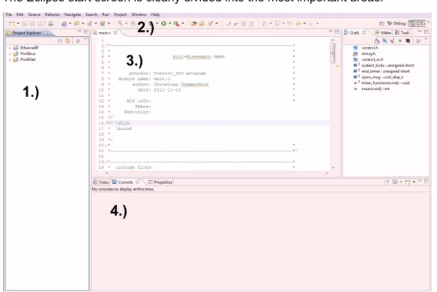
The Eclipse start screen is clearly divided into the most important areas.
Fig. 6-1. Eclipse Control III start window
1. Project Explorer 2. Toolbar 3. Editor 4. Console 6.2.1 The Project Explorer
In the Project Explorer you will find three sample projects which you can directly use and adapt. In the Project Explorer you can manage, adapt and test all your projects. After a new installation each project contains the following files: • control_io.c • control_io.h • control.h
1.)
3.)
4.)
2.)
te: 2 1.02. 2013 • *.mak • settings.mak 6.2.2 Toolbar
The Toolbar includes all the tools needed for working with Control III. 6.2.2.1 Compiler
• clean:
Used to clean the project folder. Clean deletes all the files and folders created by compiling.
• debug:
Compiles the currently selected project without optimization. The resulting control.bin is used for debugging. (See Sec. <The Debugger>).
• release:
Compiles the currently selected project. The resulting control.bin is optimized for time in order to achieve the fastest possible cycle times for your program code.
6.2.2.2 Debugging
This button is used among other things for starting the debugger. To debug you must set the corresponding port. More information can be found in Sec. <Start the Debugger>.
6.2.2.3 Configuration tools
The Configuration tools button is used for communicating with the gateway and has the following functions:
Unlock Control:
Tool for unlocking Control III in the gateway (See Sec. <Enabling Control III>).
Download Control:
The file "control.bin" is written to the gateway.
Start Control:
The Control III program in the gateway is started.
Information!
If the Control III program is at a ‘breakpoint’, the entire operating system freezes and the fieldbus interface is no longer processed
Information!
Download + Start Control:
The Control III program is first stopped, then the new program is loaded into the gateway and then started.
Stop Control:
The Control III program is stopped
Set Auto Start:
The Auto Start flag is set. The Control III program starts up automatically after each power-on.
Clear Auto Start:
The Auto Start flag is cleared.
Read Flags:
The Control III flags are read and displayed in the console.
Read Flags Cyclically:
The Control III flags are read and the display in the console refreshed cyclically. This allows for example variables to be monitored during run time.
Cycle time:
The current cycle times are displayed.
Reset Cycle Time:
The cycle time of the Control III is reset and recalculated. 6.2.3 Editor
In this window the entire C-code is written and adapted. The Editor also supports errors in the ‘C’ syntax.
6.2.4 Console
The console serves as an information window. It outputs for example error mes-sages or status mesmes-sages and displays how much memory is being used by the Control III program after compiling.
te: 2
1.02.
2013
6.3 File information
As already described in <The Project Explorer>, each project folder contains va-rious files. In this section the individual files are described in greater detail.
control_io.c
This file is used for example to break down a C program into multiple sub-modu-les so that it is clearer and easier to read.
Both functions 'read_bit' and 'write_bit' read and write a corresponding output or input bit.
control_io.h
Header for control_io.c. This file contains the function definitions for 'read_bit' and 'write_bit'.
control.h
The header file ’control.h’ contains all data types and library functions. In addition it explains the way the function and are used (See Sec. <Programming Control III>).
main.c
The ’main’ function is the “starting point” of the actual program code. It also con-tains the main loop of the program (for ; ; ).
startup.c
This file is used for initializing various memory ranges. The file has no meaning for the user.
*.ld
This is the linker file and specifies the corresponding memory ranges in the gate-way. The file has no meaning for the user.
*.mak
This file specifies all the information needed by the compiler. The file has no mea-ning for the user.
int read_bit (AASiProcessData idi, int slave_addr, int bit) idi = Slave input data
slave_addr = Address of the corresponding slave bit = Slave input bit (0-3)
void write_bit (AASiProcessData odi, int slave_addr, int bit, int value) odi = Slave output data
slave_addr = Address of the corresponding slave bit = Slave output bit (0-3)
settings.mak
In this file the communication port for the gateway is specified. More detailed in-formation can be found in Sec. <Setting the port>.
6.4 Setting the port
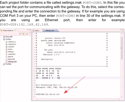
Each project folder contains a file called settings.mak PORT=COM3. In this file you can set the port for communicating with the gateway. To do this, select the corres-ponding file and enter the connection to the gateway. If for example you are using COM Port 3 on your PC, then enter PORT=COM3 in line 30 of the settings.mak. If you are using an Ethernet port, then enter for example
PORT=UDP:192.168.42.149.
Fig. 6-2. Eclipse settings.mak
6.5 Creating a new project
After a new installation the Project Explorer contains sample projects for each gateway having Control III. This makes it possible to start programming directly after installing Eclipse Control III.
If you still want to create a new project, proceed as follows: Select a new ‘C Project’ under 'File' -> 'New'.
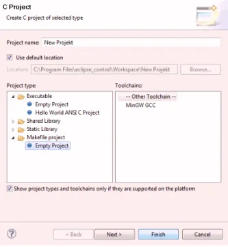
Assign a new project name and select an empty ‘Makefile Project’. Confirm the prompt with 'Finish'.
te: 2
1.02.
2013
Fig. 6-3. New Control III project
Now you will find a new empty project folder in the Project Explorer. Right-clicking on the new project and ‘Import…’ allows you to add all the necessary project files for your gateway.
Select 'File System' and then click on 'Next'.
Now select 'Browse...' and navigate to your Eclipse installation .../ eclipse_control/Templates/
Now select the gateway you are using. EthernetIP
Profibus ProfiNET
Select 'Select All' and Finish.
To apply all settings, select 'Yes to All' in the following prompt. 6.6 A sample project
In the following section the complete procedure for writing the code up to starting in the gateway is explained.
6.6.1 The C-code
In the sample program the outputs on a 4I/4O slave having Address 1 are set and cleared one after the other every second. To do this change the main.c as follows:
/*---* * include files * *---*/ #include "control.h" #include "string.h" #include "control_io.h" /*---* * local definitions * *---*/ /*---* * external declarations * *---*/ /*---* * public data * *---*/ /*---* * private data * *---*/ static unsigned short system_ticks;
static unsigned short end_timer;
/*---* * private functions * *---*/ static void timer_function ( void )
{
/* timer interrupt every 10 ms */ system_ticks++;
}
/*---* * public functions * *---*/ int main ( void )
{
//initialization of the Debugger //cctrl_func.CCtrlBreakpoint(); unsigned charctrl_flags; int i = 0; int x = 1; AASiProcessData odi[2]; AASiProcessData idi[2]; AASiCtrlAccODI acc_odi; AASiEcFlags ecflags;
te: 2
1.02.
2013
/* We want to access all odis */ for (i=0;i<32;i++)
{
acc_odi[i] = 0xFF; }
cctrl_func.AASiWriteCtrlAccODI ( 0, acc_odi, 0, 64 ); /* init timer function with 10ms ticks */
cctrl_func.CCtrlInitTimer ( 10, timer_function ); /* init watchdog */
//cctrl_func.CCtrlInitWdg( 10 ); // clear outputs from slave 1 odi[0][0] = 0x00;
for(;;) {
/* trigger watchdog */
//cctrl_func.CCtrlTriggerWdg();
/* Define data exchange for AS-i Circuit 1 and 2*/ cctrl_func.AASiDataExchange(0, odi[0], idi[0], &ecflags); cctrl_func.AASiDataExchange(1, odi[1], idi[1], &ecflags); //Timer 1 100 * 10ms = 1sec.
if ( ((unsigned short)(system_ticks - end_timer)) > 100) {
// set and clear outputs circuit=1, slave=1, output=0-3 if (x == 1) write_bit(odi[0], 1, 0, 1); else if (x == 2) write_bit(odi[0], 1, 1, 1); else if (x == 3) write_bit(odi[0], 1, 2, 1); else if (x == 4) write_bit(odi[0], 1, 3, 1); else if (x == 5) write_bit(odi[0], 1, 0, 0); else if (x == 6) write_bit(odi[0], 1, 1, 0); else if (x == 7) write_bit(odi[0], 1, 2, 0); else if (x == 8) write_bit(odi[0], 1, 3, 0); x++; if (x == 9) x = 1; end_timer = system_ticks; } /* to check Cycletime */ cctrl_func.CCtrlEvalCycletime();
/*read flags if we should stop control*/ cctrl_func.CCtrlReadFlags( &ctrl_flags ); if ( !( ctrl_flags & CCTRL_FLAG_RUN ) ) {
return 1; }
} }
6.6.2 Compiling
The C-code you have created must now be translated for the processor. To do this, select “release” under the option “Compiler” in the toolbar. A “release” folder is created and your project folder now contains the corresponding binary file ‘con-trol.bin”.
6.6.3 Downloading
To load the newly created program into the gateway, go to your project folder and select the file settings.mak and enter the corresponding port for your gateway. For additional information see Sec.<Setting the port>.
Next go to the toolbar and under the configuration tools select: Download Control. If the download was successful the following message appears in the Eclipse console:
6.6.4 Starting Control III
To start and test the program, go to Toolbar / Configuration tools and select the Start Control button. The following message is displayed:
6.7 The Debugger
A Debugger is a programming tools used for diagnostics and identifying program-ming errors. If the debugger function is used, the entire operating system is sus-pended during diagnostics.
6.7.1 Initializing
++++ CONTROL III ++++
communication port set to UDP:192.168.42.157. writing C-Control control.bin to Master ... ... o.k.
closing control.bin ... have a nice day.
83
Control 3 reset
Information!
The debug function serves only to test how your program runs. The Debugger cannot be used for diagnosing your hardware configuration.
te: 2
1.02.
2013
Using this line stops the operating system and allows Eclipse to communicate with the processor. At this point the Debugger is given the program data and it jumps to the next user-defined breakpoint of the Control III program.
6.7.2 Debugger overview 1. Control Panel 2. Tasks 3. Debugger Overview 4. Code Overview 5. Disassembly 6. Console Information!
The Debugger should not be initialized in the main loop of the program code ( for (;;) ), since this breakpoint is not controlled by Eclipse and therefore cannot be stop-ped.
1.)
2.)
3.)
4.)
5.)
6.7.2.1 The Control Panel
The Control Panel is used for controlling the Debugger.
Resume (F8):
The 'Resume' button causes the Control III program to continue until it reaches a new breakpoint. If no new breakpoint is reached within 10 seconds, the Debugger in Eclipse automatically stops and a corresponding message appears in the con-sole.
Terminate (Ctrl + F2):
Terminate quits the Debugger and allows the Control III program to continue run-ning even if there are no breakpoints in the code.
Step Into (F5):
The ’Step Into’ button is used for jumping by one program line in the code.
Step Over (F6):
’Step Over’ is used for example to skip a function call. 6.7.2.2 Tasks
In this window all programs being used which are controlled by Eclipse are dis-played. This window has no great meaning for the user.
6.7.2.3 Debugger Overview
Information!
When using the Debugger no delays of longer than 10 seconds are possible, since the Debugger is automatically stopped. This is for quitting the Debugger when communica-tion is absent or incorrect.
Information!
The StepInto function can only work reliably if the program code has been translated as “debug”.
te: 2
1.02.
2013
Variables:
In the Variables tab of the “Debugger overview” all the existing variables and their values can be displayed. Right-clicking in the window allows you to use ‘Add Glo-bal Variables’ to add additional variables to the view. The value of the variables is always displayed in hex format. The view can be changed to binary or decimal by right-clicking on ‘Format’.
Breakpoints:
The Breakpoints tab contains an overview of all breakpoints controlled by and used in Eclipse including the program line. Individual breakpoints can be deleted by right-clicking.
6.7.2.4 Code overview
This window allows you to always see at which point in the program code the De-bugger is currently located. Double-clicking n ext to the corresponding code line allows you to set or delete a breakpoint.
6.7.2.5 Disassembly
Like the Code overview window, the Disassembly window shows exactly where the Debugger is currently. Here both the memory address and the associated as-sembler code are displayed.
6.7.2.6 Console
The console serves as an output window and tells you about the Debugger sta-tus.
6.7.3 Start the Debugger
The Debugger is started from the Control Panel.
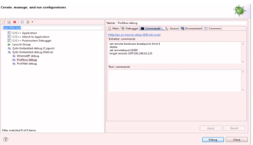
Before you can establish a connection with the target, you must define the port for the gateway under ‘Debug-Configuration’. To do this, click on the ‘Commands’ tab and under target remote enter the port. (e.g. target remote
UDP:192.168.42.33 or COM3).
Information!
As soon as the Debugger is started you first see an empty window with the text “Source not found.” At this point the Debugger is in the operating system and does not know the associated C-code.
Fig. 6-4. Debug Configuration...
6.7.4 Example
To illustrate the Debugger, here is a sample program which sets an output bit (0-3) of the slave having Address 1 in every main loop pass. Following is the corres-ponding program code.
te: 2 1.02. 2013 *---* * include files * *---*/ #include "control.h" #include "string.h" #include "control_io.h" /*---* * local definitions * *---*/ /*---* * external declarations * *---*/ /*---* * public data * *---*/ /*---* * private data * *---*/ static unsigned short system_ticks;
static unsigned short end_timer;
/*---* * private functions * *---*/ static void timer_function ( void )
{
/* timer interrupt every 10 ms */ system_ticks++;
}
/*---* * public functions * *---*/
int main ( void ) {
//initialization of the Debugger cctrl_func.CCtrlBreakpoint(); unsigned charctrl_flags; int i = 0; int x = 1; AASiProcessData odi[2]; AASiProcessData idi[2]; AASiCtrlAccODI acc_odi; AASiEcFlags ecflags;
/* We want to access all odis */ for (i=0;i<32;i++)
{
acc_odi[i] = 0xFF; }
cctrl_func.AASiWriteCtrlAccODI ( 0, acc_odi, 0, 64 ); /* init timer function with 10ms ticks */
cctrl_func.CCtrlInitTimer ( 10, timer_function ); /* init watchdog */
//cctrl_func.CCtrlInitWdg( 10 ); // clear outputs from slave 1 odi[0][0] = 0x00;
te: 2
1.02.
2013
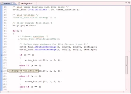
Now create two breakpoints by double-clicking in the margin of the program code on the corresponding code line. In our example we use both lines 103 and 109. The line in which a breakpoint was added is indicated by a period. These lines are shown later in the Debugger overview under Breakpoint and this information conveyed to the processor during initialization.
for(;;) {
/* trigger watchdog */
//cctrl_func.CCtrlTriggerWdg();
/* Define data exchange for AS-i Circuit 1 and 2*/ cctrl_func.AASiDataExchange(0, odi[0], idi[0], &ecflags); cctrl_func.AASiDataExchange(1, odi[1], idi[1], &ecflags); if (x == 1) { write_bit(odi[0], 1, 0, 1); } else if (x == 2) { write_bit(odi[0], 1, 1, 1); } else if (x == 3) { write_bit(odi[0], 1, 2, 1); } else if (x == 4) { write_bit(odi[0], 1, 3, 1); x = 1; } x++; /* check Cycletime */ cctrl_func.CCtrlEvalCycletime();
/*read flags if we should stop control*/ cctrl_func.CCtrlReadFlags( &ctrl_flags ); if ( !( ctrl_flags & CCTRL_FLAG_RUN ) ) { return 1; } } } /*---* * eof * *---*/
Fig. 6-5. Marking a breakpoint in the program code
Now compile the program by clicking on ‘Debug’ in the toolbar under Compiler. A new control.bin file without optimization is created. Load this file into the gateway as already described under <Editor>.
6.7.4.1 Starting the Debugger
Before you can begin debugging, you must set the port. Click in the toolbar under Debugger on ‘Debug Configurations…’ Here open the ‘Commands’ tab and under ‘target remote’ enter your port (e.g. UDP:192.168.42.157 or COM1) for the gate-way and click on 'Apply'.
Of your Control III program is already at a breakpoint, you can start the Debug-ger directly from ‘Debug’. A breakpoint is displayed in the gateway with number
te: 2
1.02.
2013
If this is not the case, quit entry with ‘Close’ and start your program. You can now directly start the Debugger by clicking for example on ‘Profibus debug’ in the tool-bar.
6.7.4.2 Using the Debugger
After you have started the Debugger, it is configured for the application. The De-bugging window is automatically opened by Eclipse. Under Breakpoints you now see the first breakpoint which is run by the program code. This is the Debugger initialization. In this case you are shown an empty window. Click on ‘Resume’. The program code is run up to the corresponding line with the first breakpoint and stopped.
Fig. 6-6. First breakpoint in Debug-mode
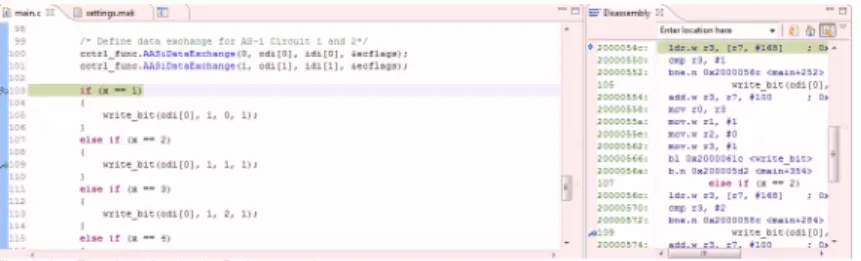
You can also click on ‘Variables’ in the Debugger overview to display all the vari-ables which are used (see Sec. <Debugger overview>). Click on ‘Resume’. The Debugger again stops at this point and not at the second breakpoint. This is be-cause the second breakpoint is not reached until the variable ‘x’ in our sample program has a value of 2. You can display the value of the variable by moving the mouse cursor over the corresponding variable. The variable x now has a value of 2. Click again on ‘Resume’ to jump to the breakpoint in line 109.
Fig. 6-7. Second breakpoint in Debug-mode
For this code line you can choose from between ‘Step over’ and ‘Step into’. ‘Step over’ causes the program to skip to line 120, in other words skips the function call ‘write_bit(…)’ and continues from the next valid line in the code. ‘Step into’ opens
79
the corresponding file (control_io.c) and continues ‘Debug-mode’ from the corres-ponding location. If you want to jump to the next breakpoint, click again on the ‘Resume’ button. Quit the Debugger by clicking on ‘Terminate’.
te: 2
1.02.
2013
7.
Technical Data
The following section provides an overview of all the key technical data for Cont-rol III.
7.1 Overview
• 28 kB program memory (can be split between ROM and RAM) • 1kB non-volatile parameters
• 256 bytes of flag memory
• Control program and parameters also on chip card
• A configurable timer interrupt which can be used to create any number of timers
• Programmable timer times from 1 to 232 ms
• Up to 248 I/O and 248 analog values using AS-i slaves • Unique 32-bit ID in the device
• Simple determination of the cycle time
• Eclipse with GCC and GDB as a complete development environment
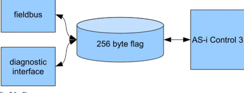
7.2 Flags
The flag area is transparent and administered by the user.
Fig. 7-8. Flag area
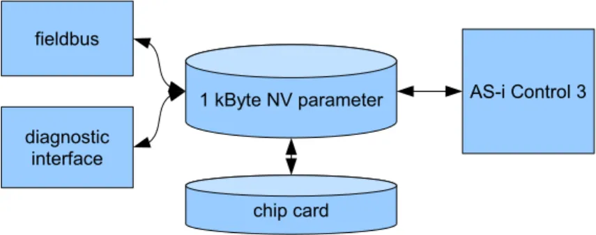
7.3 Non-volatile parameters
The non-volatile parameters are transparent and administered by the user.
26-=$%
0(
$-%
$%
Fig. 7-9. Non-volatile parameters
7.4 Access rights to the output data area
Fieldbus and the Control III program can both set outputs at the same time. Ac-cess rights can be assigned by the bit or by channel.
Fig. 7-10. Access rights for the output data area
#=K7%%
0(
$-%
$%
7%
9
9
9(
93
(
3
1
1
1(
13
9
9(
3
$-- 7-$ 7% 7-% % %$ 7%te: 2
1.02.
2013
8.
Error Messages
This section is intended to help you to troubleshoot and resolve any problems which may arise.
8.1 error: control not activated!
If the Eclipse console displays the following message, Control III needs to be en-abled for your gateway (see Sec. <Enabling Control III>).
Fig. 8-11. error: control not activated
8.2 error: wrong control version
If the message 'error: wrong control version' is displayed in the Eclipse console, you are using a gateway having a different Control version which is not capable of ‘C’ programming. In this case refer to manufacturer’s support.
Fig. 8-12. error: wrong control version!
8.3 Launching problem
This error message indicates that Eclipse is not associated with your project. Simply click in the Editor window and make your entry again.
Fig. 8-13. Launching problem
8.4 No or an incorrect cycle time is displayed.
If you read the cycle time on Eclipse and a value of 0 keeps appearing, the follo-wing line is missing in the program code:
8.5 The gateway doesn’t stop at a breakpoint.
If the gateway doesn’t stop at a breakpoint, it is possible that the auto-start flag is set or the following line for initializing the Debugger is missing in the program co-de:
8.6 The program always goes to the same breakpoint.
If this happens and there is no Debugger initialization in the code, the error is in the program code. The most frequent cause is an un-initialized pointer. Please check your program code. If you have also set the Autostart flag, you can perform a reset when starting the gateway. To do this, press both the ‘Mode’ and ‘Set’ keys while turning on the gateway. The existing program code is deleted and the gateway starts back up.
8.7 The Control III can’t affect any outputs.
Check whether the slaves are correctly projected and the gateway indicates no configuration error. If needed, project the slaves again. If the error persists, you may not have access rights. These are assigned by the following function:
Additional information can be found in Sec. <AS-i Read Ctrl Acc AODI>.
/* check Cycletime */
cctrl_func.CCtrlEvalCycletime();
//initialization of the Debugger cctrl_func.CCtrlBreakpoint();