Study of Wind Analysis on Multi-Storey Building
for a Regular and Irregular Plans
Tharan SN1, Dr. Jagadish G kori2 1
P.G. Student, Department of Civil Engineering, Govt engineering college, Devagiri, Haveri, Karnataka, India
2
Professor and Head of the Department, Department of Civil Engineering, Govt engineering college, Devagiri, Haveri, Karnataka, India
Abstract: The present study deals with the wind analysis of G+15 multi-storied structure. the principal wind speed considered is 50m/s. For the investigation the software tool is used, E-TABS 2013 (Extended three-dimensional analysis of building system) is that the tool to analyses the multi-storey structure. during this study the consequence of wind on multi story structure for plan of regular and irregular is examined. In addition, the effect of shape on wind investigation is also analysed. during this study the comparison of impact of wind for Rectangular, and U-shape, Stepped building structure is exhibited. The analysis consist typical characteristic comparison associated with storey displacement, storey drift, Storey stiffness, etc. The classification of structure as Class-B of wind zone thought for height is employed for modelling of structure. Modelling in category-2,3,4 is taken to check the result. This study of structure for plan of regular and irregular concludes that which shape and terrain category is more dominant for story displacement, story drift, storey stiffness etc. and also which shape is safer for wind effect. Over all analysis suggests rectangular structure for long wind or across wind direction is superior because of massive stiffness and fewer displacement against wind.
Keywords: E-TABS, multi-storied structure, storey displacement, storey drift, Storey stiffness, terrain conditions, wind analysis.
I. INTRODUCTION
For engineering structures wind load is one of the necessary design loads for high rise structures. For tall high-rise buildings and structural design depends on the wind load as its dynamic in nature. because the impact of wind load on tall structures is distributed over the broader surface and also the intensity of the load is additionally high. In general, for the proposition of tall structures, both wind as well as seismic loads should be considered. As per IS 875(Part 3):1987, wind associates with a structure, every positive and negative pressures happen at the same time, the structure ought to have adequate strength to resist the applied loads from these weights to prevent wind attracted building failure. Load applied on the structure is moved to the structural system then passing through the footing and finally moved to the ground. Lateral loads due to wind which that performing on multi story building will cause shake in the higher stories. This might be impact caused due to wind at higher stories because the wind intensity is increasing with graduating heights. Thus, the multi-story building conjointly act as a portal frame the instant concentrating at base due to lateral wind forces are bigger. Thus, it’s necessary to nullify displacement in lateral direction by appropriate design.
A. Irregularities in Structure
There are numerous forms of inconsistencies in the structure's dependent upon their area and scope, but mainly, they’re divided into two groups plan irregularities and vertical irregularities.
B. Terrain Categorys
1) Category I: The Fig.2 showing Exposed open piece of land with few or no obstructions and during which the typical height of any object close the structure is smaller amount than 1.5m.
Fig.2 Showing different places of terrain category-I
2) Category II: The Fig.3 showingOpen piece of land with well scattered obstructions having heights typically between 1.5 to 10 m.
Fig.3 Showing different places of terrain category-II
3) Category III: The Fig.4 showingpiece of land with several closely spaced obstructions having the scale of building-structures up to 10 m tall with or while not many isolated tall structures.
Fig.4 Showing different places of terrain category-III
4) Category IV: The Fig.5 showing piece of landwith varied giant high closely spaced obstructions
II. OBJECTIVES OF THE PROJECT
A. To carry out modelling and analysis for 15 storey building using E-TABS Software.
B. To search out the parameters like storey displacements, storey shear, and relative storey drifts.
C. To study the wind impact on these models.
D. To study the regular and irregular structures for dynamic properties.
E. To check the behavior of the regular and irregular structures under strong wind effect for different terrain categories.
F. To analyse the structure for structure with shear wall.
III. ANALYSIS
A. Architectural And Structural Parameters Considered For Analysis
Sl no Data Description 1 Dimension of building 25 * 20 m 2 Number of storey (G+15)
3 Storey height Ground floor-3.5m & 1st -15th floor-3.0m
4 Grade of concrete and steel M25 for Beams and Slabs M30 for columns and Fe500 steel 5 Thickness of slab 150mm
6 Column size 300mm X 800mm 7 Beam size 300mm X 600mm 8 Live load 3 kN/m2 9 Floor finishes 1.5 kN/m2 10 wall load 11.6 kN/m2 11 Wind speed 50m/s 12 Structural class B 13 Location of building Delhi 14 Terrain category II, III, IV 15 Building height (H) 48.5m
1) Model 1: Plan of regular RC frame structure.
2) Model 2: Plan of horizontal irregular RC frame structure.
3) Model 3: Plan of vertical irregular RC frame structure.
Fig.7 3D view of regular, horizontal irregular and vertical irregular structure
IV. RESULTS AND DISCUSSION
A. Storey Displacement
Table.1 Showing storey wise nodal displacement for all models
Story number Model-1 (mm) Model-2 (mm) Model-3 (mm) 15 48.5 86.5 55.4 14 47.9 85.1 54.5 13 47 83.1 52.8 12 45.6 80.4 50.5 11 43.8 77.0 48.5 10 41.7 72.9 46.1 9 39.2 68.3 43.2 8 36.3 62.9 39.8 7 33.1 57.0 36.0 6 29.6 50.5 32.3 5 25.7 43.5 28.0 4 21.5 36.0 23.3 3 17.1 28.0 18.2 2 12.3 19.6 12.8 1 7.30 10.7 7.00
Fig.8. Graph showing displacement v/s storey numbers
From the above Fig.8 showing the variation of displacement v/s storey number and it shows the displacement in TG-4 is smaller amount as compared to other terrain categories.
0 20 40 60 80 100
0 5 10 15 20
D
is
p
la
ce
m
en
t(
m
m
)
Storey numbers
Model-1
Model-2
B. Storey Drift
Table.2 Showing storey wise drift for all models
Story number Model-1 Model-2 Model-3
15 0.000139 0.000453 0.00039
14 0.000198 0.000673 0.00066
13 0.000265 0.000902 0.00087
12 0.000333 0.001127 0.00065
11 0.000401 0.001348 0.00082
10 0.000466 0.001564 0.00097
9 0.00053 0.001772 0.00113
8 0.000591 0.001971 0.00126
7 0.000649 0.002161 0.00125
6 0.000704 0.002340 0.00142
5 0.000755 0.002508 0.00156
4 0.000802 0.002662 0.00169
3 0.000842 0.002805 0.00181
2 0.000842 0.002964 0.00194
1 0.000621 0.00306 0.00200
Fig.9. Graph showing drift v/s storey numbers
From the above Fig.9 showing the variation of drift v/s storey number and it shows the drift is more in horizontal irregular structure (model-2) as compared to alternative models.
C. Storey Stiffness
Table.3 Showing storey stiffness for all models
Storey numbers
Model-1 (kN/m) Model-2 (kN/m) Model-3 (kN/m)
Without shear wall(x105)
With shear wall(x105)
Without shear wall(x105)
With shear wall(x105)
Without shear wall(x105)
With shear wall(x105)
15 2.896 2.296 0.825 0.870 0.576 0.790
14 4.621 4.786 1.577 1.903 1.173 2.057
13 5.406 6.937 2.083 2.880 1.806 3.316
12 5.855 8.772 2.448 3.798 3.230 4.739
11 6.155 10.364 2.730 4.677 3.614 5.966
10 6.377 11.798 2.961 5.543 3.850 7.265
9 6.552 13.153 3.159 6.427 4.121 8.662
8 6.696 14.524 3.336 7.377 4.825 10.438
7 6.824 16.026 3.502 8.463 6.593 13.966
6 6.944 17.807 3.666 9.791 6.886 16.304
5 7.061 20.094 3.836 11.544 7.044 19.204
4 7.191 23.304 4.027 14.078 7.185 23.186
3 7.396 28.307 4.291 18.252 7.393 29.421
2 7.967 37.995 4.854 26.704 7.966 41.283
1 10.642 58.532 7.090 51.639 10.646 53.723
0 0.001 0.002 0.003 0.004
0 2 4 6 8 10 12 14 16
D
ri
ft
Storey numbers
Fig.10. Graph showing stiffness v/s storey numbers.
From the above Fig.10 showing the variation of Stiffness v/s story number and it the stiffness is more in bottom stories and with shear wall structure, while not shear wall structure showing very terribly low stiffness.
[image:6.612.122.492.274.451.2]D. Maximum Displacement
Table.4 Showing maximum displacement for all models
Type of structure Displacement at WY (mm) Displacement at WX (mm) Regular 48.5 24.7
Horizontal irregular 86.5 59.3 Vertical irregular 55.4 31.9
Fig 11. Graph showing maximum displacement in x & y direction
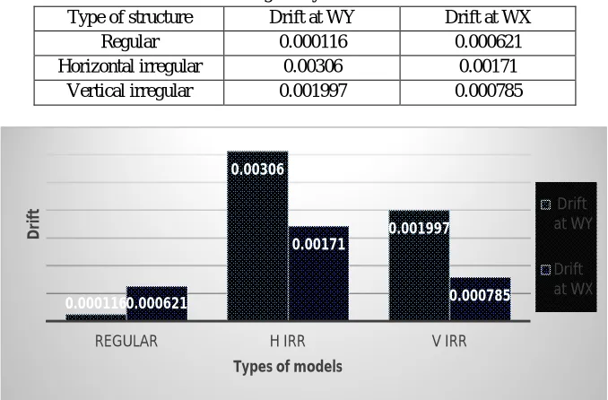
[image:6.612.136.475.498.721.2]E. Maximum Storey Drift
Table.5 Showing storey drift for all models
Type of structure Drift at WY Drift at WX Regular 0.000116 0.000621 Horizontal irregular 0.00306 0.00171
Vertical irregular 0.001997 0.000785
Fig 12. Graph showing maximum storey drift in x & y direction
0 2000000 4000000 6000000 8000000
0 5 10 15 20
St if fn e ss (k N /m ) Storey numbers Without shear wall With shear wall 48.5 86.5 55.4 24.7 59.3 31.9
REGULAR H IRR V IRR
D is p la ce m e n t( m m )
Types of models
Displacement at WY Displacement at WX 0.000116 0.00306 0.001997 0.000621 0.00171 0.000785
REGULAR H IRR V IRR
D
ri
ft
Types of models
Drift at WY
F. Maximum Storey Shear
Table.6 Showing storey shear for all models
Type of structure Shear at WY (KN) Shear at WX (KN) Regular 2458.5 1966.83 Horizontal irregular 2119.89 1695.9097
Vertical irregular 1844.77 1936.5499
Fig.13 Graph showing maximum storey Shear in both x & y direction
From the above Fig.11 and Fig.12 shows the displacement is more in wind force y direction at horizontal irregular structure. and the maximum drift is more in wind force y direction at horizontal irregular structure and very less drift in regular structure and Fig.13 shows storey shear is more regular structure in wind force y direction.
G. Results for Models at Different Terrain Categorys
Table.7 Nodal displacement comparison (mm) compare
to m1
increase
(%) decrease (%)
compare to m2
increase
(%) decrease (%)
compare to m3 increase (%) decrease (%) M2 42.35 - M1 - 42.35 M1 9.44 - M3 - 9.44 M3 - 36.34 M2 36.34 - The Table.7 gives following results
1) There is a nominal decrease in displacement in model-3 when subjected to any or all sort of loading in compared with model-1, there is an increase of displacement in model-2 as compared to model-1.
2) There is a decrease in the displacement in model-1(42.35%) and model-3(36.34%) as compared to model-2.
3) When model-3 compared with all models a rise in displacement in model-1(9.44%) and model-2(36.34%). Table.8 Storey Drift Comparison
Compare to M1 Increase (%) Decrease (%) Compare to M2 Increase (%) Decrease (%) Compare to M3 Increase (%) Decrease (%) M2 71.25 - M1 - 71.25 M1 51.81 - M3 - 51.81 M3 - 34.93 M2 34.93 - The Table.8 gives following results:
1) There is a nominal decrease in drift in model-3 when subjected to all type of loading in comparison with model-1, there is an increase of drift in model-2 as compared to model-1.
2) There is a decrease in the drift in model-1(71.25%) and model-3(34.93%) as compared to model-2.
3) When model-3 compared with all models there’s a rise in drift in model-1(51.81%) and model-2(34.93%).
2458.5
2119.89
1844.77 1966.83
1695.9097 1936.5499
REGULAR H IRR V IRR
Sh e ar (k N )
Types of models
V. CONCLUSIONS
In this work an effort has been created to examine the performance of various RC frame building like regular, horizontal irregular and vertical irregular structures for various terrain category’s far wind topography.
Totally G+15 storey are considered for the analysis. The conclusion based on analysis presented here
A. The displacement in horizontal irregular structure (U-Shape) is 42.35% more as compared to model-1, the displacement will increases abruptly as increase in height of storey, thus U-Shape structure isn’t preferred in wind zone.
B. The displacement is 30.88% less in terrain catagory-3 and 12.36% less in terrain category-4 as compared to terrain category-2.
C. The drift is 12.36% a lot of in terrain category-2 and 19.42% a lot of in terrain category-3 as compared to terrain category-4.
D. During this study the drift is more in horizontal irregular structure as compared to other structures.
E. The horizontal structure (U-Shape) is a lot of sensitive to the wind as compared to different structures
F. Over all analysis suggests rectangular structure for long wind or across wind direction is preferred because of giant stiffness and fewer displacement against wind.
REFERENCES
[1] Potnuru Avinash, Shaik Yajdani: “Comparative Study of Different Plan Configuration Building using Wind Analysis” International Journal of Science Technology & Engineering, Vol4, Issue2, PP:(72-80), ISSN (online) :2349-784,August2017.
[2] Shraddha J. Patil, Mahesh Z. Mali, Dr.R.S. Talikoti: “Effect of wind load on high rise structure.” International Journal of Engineering and Technical Research (IJETR), Volume-3,Issue-7,PP(384-386),ISSN:2321-0869,July2015.
[3] Bhumika Pashine, V. D. Vaidya, Dr. D. P. Singh: “Wind analysis of multistoried structure with T shape and L Shape geometry.” International Journal of Engineering Development and Research, Volume-4, Issue-3, PP (70-77), ISSN: 2321-9939, July 2016
[4] Alkesh Bhalerao, S.B.Shinde: “Effect Of Structural Shape On Wind Analysis Of Multistoried RCC Structures”. International conference on recent trends in engineering Science Technology & management, Vol 16, PP (1159-1163), December 10 (2016).
[5] Shaikh Muffassir, L.G. Kalurkar: “Study of Wind Analysis of Multi-story Composite Structure for Plan Irregularity.” IOSR Journal of Mechanical and Civil Engineering (IOSR-JMCE), Volume-04, Issue-09, PP (36-45), ISSN 2348-7550, September 2016.
[6] Madhurima Dutta: “Wind Analysis and Design of a Multi Storied Structural Frame Considering Using Staad Pro”. International Journal of Advances in Mechanical and Civil Engineering, ISSN: 2394-2827, Vol-4, Issue-5, Oct.-2017.
[7] Mohammed Asim Ahmed, Moid Amir, Savita Komur, Vaijainath Halhalli: “Effect of Wind Load On Tall Buildings in Different Terrain Category”. International Journal of Research in Engineering and Technology, ISSN: 2319-1163, Volume: 04, PP (107-111), Issue: 06, June-2015.
[8] Syed Rehan, S.H.Mahure: “Study of Seismic and Wind Effect on Multi Storey R.C.C. Steel and Composite Building”, International Journal of Engineering and Innovative Technology (IJEIT), ISSN: 2277-3754, Volume 3, PP (78-83), Issue 12, June 2014.
[9] Swati D.Ambadkar, Vipul S. Bawner: “Behavior of multistoried building under the effect of wind load”. Int. Journal of Applied Sciences and Engineering Research, ISSN:2277 – 9442, Vol. 1, PP (656-662), Issue 4, 2012.
[10] T.V.V.S. Murali Manohar and N. Jitendra Babu: “Effect of Shape of Tall Buildings Subjected to Wind Loading”. International Journal of Civil Engineering and Technology (IJCIET), ISSN: 0976-6316, Volume 8, PP (591–601), Issue 1, January 2017.
IS CODES USED:
[11] IS: 800-2007, “Code of practice for General construction in Steel” Bureau of Indian Standards. [12] IS 456 -2000, “Plain and reinforced concrete - Code of practice”, Bureau of Indian Standards, New Delhi.