Design and Evaluation of an MSP-based Body Area
Network Management Architecture using JMX
Eduardo Rubio Paniza
Thesis for a Master of Science degree in Telematics from the University of Twente, Enschede, The Netherlands,
June 2009
Abstract
The increasing availability of mobile devices and the ongoing improvement on their capabilities is leading to further explore their possibilities. As an example of this exploration, the use of mobile devices in Body Area Networks has gained in recent years the attention of the research community. But,
although Body Area Networks are lately being subject of extensive research, there is one key aspect that has been marginally addressed: their operational management.
This thesis presents an architecture for the remote management of a Body Area Network that makes use of JMX as management technology and that is fully aligned with the Mobile Service Platform, which is in turn based on the Jini Surrogate Architecture specification. Furthermore a prototype
Table of Contents
Abstract ... 2
List of Figures ... 5
List of Tables ... 6
Preface ... 7
1 Introduction ... 8
1.1 Motivation ... 8
1.2 Objectives and scope ... 9
1.3 Approach ... 9
1.4 Thesis structure ... 10
2 Background information ... 11
2.1 Body Area Network (BAN) ... 11
2.2 Jini Service Architecture ... 13
2.2.1 Clients ... 14
2.2.2 Lookup Service ... 14
2.2.3 Services (service provider) ... 14
2.2.4 Discovery, Join and Lookup protocols ... 15
2.2.5 Events ... 17
2.2.6 Leasing ... 17
2.2.7 Jini and RMI ... 17
2.3 Jini Surrogate Architecture ... 18
2.3.1 Interconnect Protocol ... 18
2.4 The Mobile Service Platform ... 19
2.4.1 MSP ... 20
2.4.2 Context Aware MSP ... 20
2.5 Java Management Extensions ... 21
2.5.1 Agent level ... 22
2.5.2 Distributed Services Level ... 22
2.5.3 Instrumentation level ... 23
3 Remote BAN Management with JMX and MSP ... 25
3.1 BAN Management Requirements ... 25
3.3 Evaluation of Requirements ... 29
4 The JMXMSP Connector ... 30
4.1 JMXMSP Connector Overview ... 30
4.2 JMXMSP Connector Components ... 33
4.2.1 JMXMSPConnectorServer and JMXConnector ... 33
4.2.2 JMXMSPConnectionServer ... 34
4.2.3 JMXMSPConnection and JMXMSPConnectionSurrogate ... 37
4.2.4 ServiceServant and SurrogateServant ... 39
4.3 Network Message Exchange ... 40
5 MBeanServerSurrogate ... 44
5.1 BAN Management Surrogate Overview ... 44
5.2 MBeanServerSurrogate ... 47
5.3 Joining the Jini Network ... 52
5.4 Caching ... 53
5.5 Client – BAN Management Surrogate Interaction ... 54
6 Evaluation ... 56
6.1 Experimental Setup ... 56
6.2 Prototype Evaluation... 57
6.2.1 Retrieving information from the MBeanServer ... 57
6.2.2 Remote MBean Creation and Invocation of Exposed Methods ... 61
6.2.3 Caching demonstration ... 67
6.2.4 Using JConsole to Manage the BAN ... 69
7 Conclusions and Future Work ... 73
8 Bibliography ... 75
Appendix A – Setup Configuration ... 77
List of Figures
Figure 1. Conceptual model of a BAN [1] ... 11
Figure 2. Generic architecture of a BAN ... 12
Figure 3. Jini Discovery, Join and Lookup protocols. ... 16
Figure 4. Overview of the JMX Architecture. ... 23
Figure 5. Proposed BAN Management Architecture. ... 26
Figure 6. ServiceConnection and ServiceSurrogateConnection ... 31
Figure 7. BAN management architecture overview ... 32
Figure 8. JMXMSPConnectorServer and JMXMSPConnector. ... 34
Figure 9. JMXMSPConnectionServer and related components of the JMXMSP Connector. ... 35
Figure 10. JMXMP connector connection creation. ... 36
Figure 11. JMXMSPConnection creation. ... 36
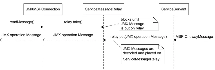
Figure 12. Incoming JMX operation message handling. ... 38
Figure 13. Outgoing JMX operation message handling. ... 38
Figure 14. JMXMSPConnectionSurrogate and related components of the JMXMSP Connector. ... 39
Figure 15. JMXMSPConnectionSurrogate initiates the connection handshake sending a OnewayMessage with OperationId = MSG_TYPE_CONNECTION_REQUEST. ... 39
Figure 16. Handshake message exchange. ... 42
Figure 17. MBeanServer operations and notifications exchange. ... 43
Figure 18. BAN management surrogate overview ... 45
Figure 19. BANManagementSurrogate retrieval and activation and MBeanServerSurrogate creation. ... 46
Figure 20. MBeanServer interface... 48
Figure 21. UML diagram of the proxy pattern. ... 48
Figure 22. Proxy pattern sequence diagram. ... 49
Figure 23. MBeanServerConnection interface. ... 50
Figure 24. MBeanServerSurrogate overview. ... 51
Figure 25. MBeanServerSurrogate caching mechanism. ... 53
Figure 26. Experimental setup. ... 56
Figure 27. Connectin JConsole to the MBeanServer proxy. ... 70
Figure 28. Initially, just the MLet and MBeanServerDelegate MBeans are registered with BAN MBeanServer... 71
Figure 29. The StateControl and Calculations MBeans are registered with the BAN MBeanServer and we modify the StateControl attribute... 71
Figure 30. When the StateControl MBean reset method is invoked, we receive a notification. ... 72
List of Tables
Preface
This thesis is not just the end of my studies. This thesis marks as well the end of a personal quest. One that started the moment I declined a vacancy to continue my studies in Spain, packed a suitcase and headed to The Netherlands with no more than a bunch of dreams and the intention of being with the woman that is now my wife. This thesis closes a chapter, while the promising first lines of the next one are already being written.
I would like to thank my supervisor, Bert-Jan van Beijnum, not just for his valuable comments and suggestions, but also for his understanding during some difficult periods.
I especially want to express my gratitude for the never-ending and invaluable support from my family and friends, both in Spain and in Holland. I owe them more of who I am today than I will ever be able to repay.
But there is someone that helped me more than anyone making this research possible: my wife. Her love and affection, her support and understanding, her sense of humor and infinite patience kindly guided my steps for the past few months. Te quiero infinito.
1
Introduction
1.1
Motivation
Over the years, mobile devices have been improving their capabilities keeping up with the fast evolution of technology. Their memory and processing power hasn’t ceased to increase, they have incorporated new connectivity options and many other new technologies that have set the potential of ultra portable devices such as mobile phones and Pocket PCs at a level unimaginable a few years ago, in many cases almost redefining their original purpose. Mobile phones are not anymore just a device to make phone calls, but a full featured portable computer with endless applications and possibilities.
As an example, and one that is key to the subject of this research, Pocket PCs have gained an important role in the area of telemedicine, a concept that is rapidly gaining popularity and used to describe the application of traditional medicine where information is exchanged over the telephone or some other communications network in order to deliver clinical care at a distance.
Being a bit more specific, Pocket PCs have become the core component to what is commonly known as Body Area Networks (BAN). A BAN is, simply put, a set of communicating devices that somebody is wearing on his/her body and although its purpose may vary it generally focuses on the collection of vital signs and parameters via a set of sensors to realize some real-time remote patient monitoring and to provide e-Health services. When data has been gathered, it may be transmitted over the internet to a different location, where a medical specialist can remotely analyze and interpret it in real-time and provide proper feedback to the patient.
But, although Body Area Networks are lately being subject of detailed study and extensive research, there is one key aspect that has been marginally addressed: the operational management of a BAN. Considering the key to Body Area Networks is to provide remote medical assistance, what happens if some settings have to be modified? Consider, for instance, that the medical specialist providing remote assistance decides to modify the sampling frequency of the sensors worn by the patient in order to provide a more detailed view of the data collected. If this can’t be done remotely the main purpose of Body Area Networks is defeated. But there is more. If necessary, how can the software that controls the patient’s BAN or one of its components be stopped, restarted or even updated? How can new
components be installed to provide new functionality to the BAN?
It becomes clear that there needs to be a means to manage the BAN resources at a distance, to maximize the intrinsic usefulness of remote medical assistance and monitoring.
In this paper we propose a remote BAN management architecture based on Java and taking advantage of JMX as Java’s management solution and MSP as supporting infrastructure for mobile service
1.2
Objectives and scope
As we will see in more detail in section 2.1, a BAN is basically a set of resources (be them hardware or software) that are in principle subject to management. So developing a BAN management infrastructure is essential in order to monitor and control the BAN providing fault management support, configuration management, accounting management, performance management and security management [1]. Based on the motivation for this research given on the previous section, the two main objectives of this research are:
1. Design an architecture for the remote management of a BAN, its resources and services using JMX and fully aligned with the Mobile Service Platform (MSP) architecture.
2. Implement and test a prototype of the designed architecture.
It is important to emphasize the remote aspect of our design. Managing BAN resources locally using Java Management Extensions is a subject that has been already addressed in [2]. Our intention with this research is to extend the use of JMX for BAN resource management to do it remotely. This introduces some new challenges that we address in this thesis in order to develop a viable solution.
1.3
Approach
In order to gain sufficient knowledge on the different subjects that this research is based on, studying related literature was the first step. More specifically, literature on Java Management Extensions, the Jini Architecture, the Jini Surrogate Architecture and the Mobile Service Platform has been studied, as well as publications from the Awareness project and from MobiHealth on the related subjects. Parallel to the study of relevant literature and due to the lack of programming experience, sufficient Java programming expertise was to be gained in order to be able to implement and test the prototype. This proved to be time-consuming but was foreseen while planning the research.
After gaining sufficient knowledge from the literature and gained some Java programming experience, the Mobile Service Platform implementation had to be understood. To accomplish this, the MSP was set up and the code documentation thoroughly studied.
The next step was to design and implement our remote management architecture. This was done by defining different phases:
• Develop a device service to serve as an MBean Server in order to turn our device manageable.
• Develop a first version of the surrogate to be uploaded to the surrogate host. This first version simply functioning as a client for the MBean Server on the device, and establish a connection between both ends using one of the standard connection mechanisms defined by JMX.
• Develop the JMXMSP Connector in order to make use of MSP Interconnect as transport protocol.
• Implement a simple testing client
Once implemented, the resulting prototype had to be evaluated and carry out some performance tests.
1.4
Thesis structure
This thesis is organized as follows:
Chapter 2 discusses the backgrounds needed to understand the technical environment in which the remote management functionality is to be made possible. To this end, we discuss the architecture of the Body Area Network (BAN), the Jini Architecture, the Jini Surrogate Architecture, the Mobile Service Platform, and the Java Management Extensions (JMX) architecture.
Chapter 3 presents an overview of our architecture for remote BAN management using JMX and MSP. In Chapter 4 the JMXMSP Connector is thoroughly described, from its design to its development. Chapter 5 then focuses on the MBean Server Surrogate design and implementation.
In Chapter 6 an evaluation of the solution developed is given, together with a demonstration of the working prototype. Then some benchmarks and performance tests are presented.
2
Background information
This chapter gives the background information needed to understand the design issues and problems to be addressed and solved within the scope of this research. First we discuss the Body Area Network (BAN), the role it plays in e.g. the monitoring and treatment of patients, and the BAN architecture and technologies used. It also explains the Jini technology: first the Jini Architecture and then the Jini Surrogate Architecture. Then the Mobile Service Platform (MSP) is discussed followed by an overview of the Java Management Extensions (JMX).
2.1
Body Area Network (BAN)
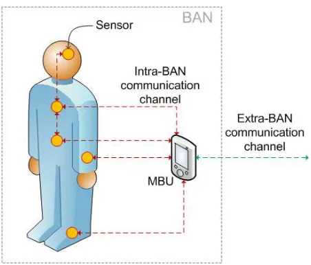
[image:11.595.73.527.519.666.2]A Body Area Network (BAN) is a network of communicating devices worn on the body that perform specific functions to provide mobile services to the user [3]. Those devices can range from small computing devices (such as PDA’s, mobile phones or a GPS receiver) and other gadgets (such as cameras, audio players or other multimedia devices) to (smart) medical sensors and actuators used to monitor and control health related conditions of a person. Besides those devices it is possible to have a central device coordinating the BAN communications and performing diverse computational tasks. The communication between the different devices within the BAN is called intra-BAN communication, whereas communications with external entities (such as other BAN’s or networks) are referred as extra-BAN communications [3]. Typical intra-extra-BAN wireless communication protocols that are used are Bluetooth and ZigBee. Wireless extra-BAN communication typically uses WLAN, GPRS, UMTS or HSDPA. For the purpose of this research we use a simplified BAN model based on that described in [4], in order to be able to focus our attention on the management possibilities of a BAN. Figure 1 shows a UML diagram presenting this simplified BAN model. The different components of this model will be discussed in the following.
Figure 1. Conceptual model of a BAN [1]
The BAN uses a Mobile Base Unit (MBU) as a central coordinating device capable of performing
data obtained from the sensor systems. The MBU is typically implemented on a PDA, but could be any other device capable of performing those functions.
The MBU serves also as a gateway between the BAN and the Back End System, performing extra-BAN communications, and possibly hosting other applications to control and manage the BAN.
Intra-BAN communications support the information exchange between on-body sensor systems and the MBU. Each connection link between a single sensor system and the MBU is an Intra-BAN communication channel (see Figure 1).
Intra-BAN communications may be wired using, for instance, copper wire or optical fiber as medium, or wireless. As for wireless technologies, the two especially suitable options are Bluetooth, which offers typical coverage of 10 meters and speeds of up to 1 Mbps on its 1.2 version (and up to 3Mbps with later versions)[5], and ZigBee offering up to 250 Kbps and 100 meters [6]. Although the Bluetooth standard (IEEE 802.15) is a very popular short range communications technology for creating Personal Area Networks, its relatively high power consumption [3] position the later as a very promising technology regarding Intra-BAN communications.
Extra-BAN communications take care of the exchange of information between the BAN, and more specifically the MBU, and the Back End System (see section 3.2). For convenience, in order to support the mobility of the person wearing the BAN, this communication uses wireless technologies. There are plenty of possibilities regarding extra-BAN communication technologies, and there is not a single answer as for which one is the most suitable option.
The answer depends on the specific requirements, and can be pinpointed considering certain criteria such as the communication range to be supported or the speed of the data exchanged required. A technology like WLAN (Wireless Local Area Network) is especially suitable for short to medium range communications, offering varying speeds depending on the specific version of the standard but typically of 11 Mbps (and up to 54 Mbps), and a typical transmission range of about 100 meters.
Wide area communications on the other hand
are typically realized using GPRS, UMTS or HSDPA technology [3,1], providing the BAN with a mobility only limited by the coverage of these networks.
[image:12.595.288.514.415.608.2]For the purpose of this research and with the simplified BAN model presented in Figure 1 in mind, we can consider the set of inter-communicating devices that compose it to be typically a set sensors gathering physiological data (such as blood pressure or heart beat rate) from the body of the person
wearing them. It is worth noting, though, that these devices are not limited to sensors, but could be any type of device. The data gathered by these sensors is transmitted to the MBU for eventual further processing.
As a remark, when the main purpose of a BAN is to use the devices that compose it to gather, process and transmit biosignals, or to offer other health-related services, the term BAN is generally understood as a healthcare BAN or health BAN [1]. In the sequel, when the term BAN is used, it should be
understood as a health BAN.
When considering the applications and uses of a health BAN within the scope of telemedicine a clear application opens up for exploration: remote patient monitoring and teletreatment. This application is explored in [7]. In [8], homecare coordinated by home nursing services and supported by the patient's BAN in combination with an ambient intelligent home environment is explored. An approach for using context-aware BAN’s for Telemedicine is presented in [9], aimed at applications in neurology.
2.2
Jini Service Architecture
The Jini technology is a service oriented architecture developed by Sun1 and designed for the construction and deployment of flexible distributed systems in order to bring together users and the resources they might require. Any resource providing some service can announce its presence on the network through the Jini architecture so users can locate the resource and make use of it. And by resource here we understand anything from hardware devices (i.e. a printer or network hard disk) to software programs or even other users providing a service.
Simply put, the purpose of Jini is to provide a sort of plug and play network that allows users and services to participate on the network in a flexible and easy way, without the need of a central controlling authority. This makes Jini particularly suitable for dynamic environments where users and resources continuously change their network locations.
Considering a typical Jini scenario would basically involve clients, services and a Lookup Service to be able to locate each other. And supporting the communications between these three parties we have a network.
As an illustrative example, we can think for example of a user with a digital camera that wants to share some pictures. The user might want to upload the pictures to an online storage device for backup, use a printer to have a hard copy of them or share them online through some photo gallery service. In such a situation, Jini would provide the infrastructure for the user to easily locate and make use of those services.
1
Note that although Jini is written in Java and much of its simplicity derives from using Java to develop the different components involved, it is not required for neither clients nor services to be developed in Java. A service that wants to be able to participate on a Jini network would be able to do so by providing a proper Java wrapper.
2.2.1 Clients
A client is basically a user, a hardware device or even a software program, that wishes to make use of some resource, be it a printing service, an online calendar application or any other service. While talking about Jini, it is important to emphasize that a client is anything that wants to use a service.
2.2.2 Lookup Service
For a client to be able to use a service it first needs to be able to locate it on the network. For this Jini provides a Lookup Service (LUS), the role of which is to serve as a central service repository. When a new service becomes available and wishes to offer its services, it first needs to register itself with the LUS so clients are able to locate it. When a client needs to make use of some service it first queries the LUS asking for it by providing its description.
2.2.3 Services (service provider)
Services are the cornerstone of the Jini architecture. According to the Jini Architecture Specification provided by Sun [10] “a service is an entity that can be used by a person, a program, or another service. A service may be a computation, storage, a communication channel to another user, a software filter, a hardware device, or another user.”
A Jini system consists of various services that can be running anywhere: on servers, desktops, laptops, mobile phones, etc. As we will see this flexibility is key for the foundations of this research.
Technically, services are objects written in the Java programming language (or at least providing suitable Java wrappers), with an interface defining the operations that can be performed by that object. Services can advertise their presence on the network to users and other services and make use of other services as well and they are free to define and make use of any appropriate communication protocol depending on their requirements.
it is supplied by the Service Provider, and can be updated by registering a newer version with the Lookup Service [10].
Service Objects generally implement one or more well known interfaces that the clients will use in order to interact with the service located on the Service Provider. These Service Objects are basically proxies and they can be implemented following different approaches, depending on how much logic of the service is going to run on the client and how much on the so called service back-end [11].
So the Service Provider may, for instance, create a Service Object with a complete implementation of the service. This is commonly known as a ‘fat’ proxy, since the whole implementation of the service is registered as a Service Object with the Lookup Service and later downloaded and used by the client. This approach may be suitable in situations in which the service implementation does not require in any way to communicate back with the Service Provider, being able to run independently from it.
A common alternative approach is to use a ‘thin’ proxy. A Service Provider may create a Service Object that simply forwards method calls from the client back to the service back-end, possibly using Remote Method Invocation (RMI).
Any intermediate combinations of the previously mentioned approaches, called smart proxies, are possible, where part of the implementation is handed in to the client and the rest is run by the service back-end [10]. However, having a back-end service allows the service to use resources local to the Service Provider host.
In any case the client will receive a Service Object in order to make use of the service. If the service has been designed so that the Service Object has to communicate back with the service back-end, both client and server sides have to use a common communication protocol. But, since the proxy used by the client has been provided by the Service Provider itself the client is not required to know anything about the communication protocol, since it is something kept between the Service Object and the Service Provider [10]. This provides convenient transparency for the client regarding how the communications are handled and allows updating the communications protocol whenever necessary without affecting the way a client is implemented.
2.2.4 Discovery, Join and Lookup protocols
The Discovery, Join and Lookup protocols provide the means for a service to announce its presence on the network and for users to be able to find it and make use of it. These protocols are the core
functionality of Jini.
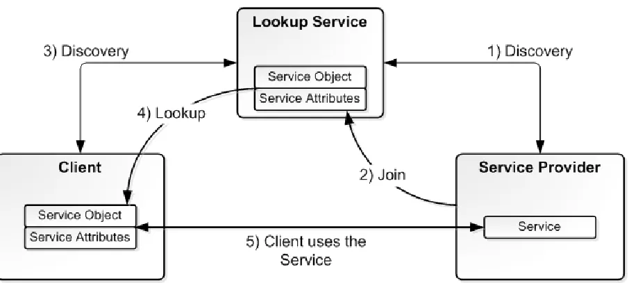
Figure 3. Jini Discovery, Join and Lookup protocols.
Any Lookup Services listening for and receiving one of such requests will return a service registrar object. The registrar object is a proxy that allows the interaction with the Lookup Service. At this point, the Service Provider is ready to perform the Join using the service registrar object to register the service with the Lookup Service by providing a suitable Service Object (Stage 2 in Figure 3).
When a client wishes to make use of some service, it first has to use the Discovery protocol to find a Lookup Service and obtain a service registrar object in the exact same way the Service Provider does (Stage 3 in Figure 3). The client, however, will use the service registrar object received in a different way, in order to query the Lookup Service for a specific service through the process called Lookup.
During the Lookup process, the client will create a service template object specifying the service it is looking for, which will serve as the search criteria for the query sent to the Lookup Service. Since the client only knows the service it is looking for through some sort of specification (typically a Java
interface), in general this object will contain one or more class objects for service interfaces and possibly other attributes [10].
When the Lookup Service receives the query from the client it will use the service template object to see if any of the Service Objects registered matches the criteria. If there is a match, a Service Object (an instance of a class for the desired service) will be returned to the client (Stage 4 in Figure 3). If the client has the class definitions for the object obtained, it can be used straightaway. Otherwise the client has to somehow obtain the proper class definitions for the Service Object [11], which typically can be
downloaded from an HTTP server (see 2.2.7).
2.2.5 Events
Like many other Java technologies, Jini provides a mechanism to support distributed events. With it, objects can register interest for being notified of events triggered by other objects. When one of such events is triggered, the object originator of the event will check if there are any event listeners in order to notify them. To further understand the Distributed Events model used by Jini we refer the reader to chapter 16 in [11].
2.2.6 Leasing
Leasing is the mechanism by which Jini avoids the presence of outdated and unnecessary resources on the system. It is safe to assume that failures can occur on the network or network components. In such situations a service could terminate unexpectedly with the Lookup Service being unaware of this. The Service Object registered with the Lookup Service would be still offered to interested clients that would unsuccessfully try to make use of the service.
Jini deals with this type of situations providing a leasing solution [10]. For instance, when a service registers itself with a Lookup Service it requests a lease for a certain period of time. If the lease is granted, the service is responsible for periodically requesting its renewal. If at some point the service fails to renew its lease, whatever the reason, the Lookup Service will remove its corresponding Service Object from its resources. At that point, the service would have to register again with the Lookup Service and ask for a new lease.
2.2.7 Jini and RMI
A basic concept behind Jini is that of moving code around between clients, services and LUS’s. This involves things such as serializing the objects to be moved from one Java Virtual Machine (JVM) to a different one, and remotely invoking methods on them. Jini builds on top of Java Remote Method Invocation (RMI) to accomplish this.
With RMI a server application (within Jini, some Service Provider) creates a remote object (an object extending the Remote interface) providing some service. Then the server creates a special type of proxy object to the service and makes it available for clients to find it. This can be done by exporting the proxy object to an RMI registry, a Jini Lookup Service or some other type of network service directory.
2.3
Jini Surrogate Architecture
For a device to be able to participate on a Jini network and offer any type of service it has to fulfill certain requirements: it has to be able to execute Java code and be able to perform the Discovery, Join and Lookup protocols described on section 2.2.4. As seen, these protocols involve, among other things, uploading and downloading Java objects or performing common RMI procedures (like downloading class definitions or creating and registering proxy objects).
But, some limited devices may not be able to meet these requirements (due, for instance, to the lack of resources necessary to run a JVM) and thus are unable to participate directly on a Jini network. In order to overcome this, the Jini Surrogate Architecture extends Jini by providing the means to allow devices unable to participate directly on a Jini network to do so aided by a third party.
Using the Jini Surrogate Architecture a limited device can provide a surrogate, a Java object that represents it and acts on its behalf. This surrogate will be uploaded (directly or indirectly) into a host-capable machine that is free of the device limitations, and running the Surrogate Host.
The Surrogate Host provides an application environment, consisting of one or more JVM’s, specially designed to host surrogates. It takes care of managing the resources used by the surrogates and controls when they are loaded, started, stopped or removed (see 2.3.1 for more details).
2.3.1 Interconnect Protocol
In order to communicate, a limited device and a Surrogate Host use the interconnect, which determines the logical and physical connection between them. Note that more than one interconnect can be defined for a single physical connection [12]. The mechanism that describes how the device and the Surrogate Host use a specific interconnect is the Interconnect protocol. Although [12] does not provide a specific implementation, it does state the minimum requirements that must be met by any interconnect protocol in order to comply with [12]. These minimum requirements are described here.
In order to establish a connection, a device and a Surrogate Host must first find each other. This is accomplished through the discovery2 phase. This mechanism is interconnect specific and different implementations are possible depending on the capabilities and requirements of the device and the interconnect itself [12]. As an example, in a possible implementation a device could broadcast its presence on the network by sending discovery packets until a receiving Surrogate Host would respond announcing its availability.
Once they’ve found one another, the surrogate retrieval phase begins, in order to load the compiled class files of the surrogate representing the device into the Surrogate Host. This can be done in different ways. The device can push the surrogate to the Surrogate Host, the Surrogate host can download it from the device or it can even be retrieved by the Surrogate Host from a different location (i.e. a third party
2
FTP or HTTP server on the network). In any case, at the end of the surrogate retrieval phase the Surrogate Host is in possession of a surrogate object, which must then be activated by instantiating it and then calling the method to begin its execution. These procedures, as well as assigning the necessary resources for the surrogate to run, are handled by the Surrogate Host and the details depend on the Surrogate Host implementation [13].
At this point the surrogate is running on the Surrogate Host, free of the limitations of the device they represent. The surrogate instance is now capable of joining the Jini network, advertising its presence on Lookup Services to offer the services provided by the device by uploading a Service Object (as described in section 2.2.4), or even directly make use of other Jini services. And whenever necessary, the surrogate may communicate with the device it represents.
Once the surrogate has been activated, either the surrogate or the Surrogate Host itself must monitor the device for liveness, making sure that the communication between the device and its surrogate it’s possible and that both are active. If at any point the communication link is broken for whatever circumstances the surrogate will be deactivated and the resources reallocated by the Surrogate Host [12]. The device must somehow be able to determine that the connection with its surrogate has been broken and should resume discovery or be ready to be re-discovered by the Surrogate Host. Note that it is the surrogate’s task to take care of liberating possible Lookup Service leases or other resources [12]. For further details on a specific interconnect we refer the reader to the IP Interconnect specification provided by Sun [14]. And for a specific implementation of the Surrogate Host a good place to start is Madison, the Surrogate Host implementation made available by Sun, that conforms both to the Jini Surrogate Architecture [12], and the Jini IP Interconnect specifications [14], and which can be found at [15].
2.4
The Mobile Service Platform
MSP is a software infrastructure originally developed in Java by the University of Twente and based on the Jini Surrogate Architecture that aims to extend the Service Oriented Architecture to the mobile device and provide a supporting infrastructure for the development of Nomadic Mobile Services (NMS). A Nomadic Mobile Service is a type of service offered by a mobile device (like a mobile phone or a PDA), capable of participating in a service discovery network and of roaming from one wireless network to another (i.e. switching from a Wi-Fi network to UMTS, GSM, etc.).
Due to their characteristics, to provide Nomadic Mobile Services certain requirements must be considered [16], such as:
• The communication between the service and the client making use of it must be seamless even while roaming from network to network. This involves dealing with things like IP address changes and Network Address Translation (NAT) problems.
networks) the upload link is lower than the download link, so data sent should be optimized to take this into account. Other considerations involve intermittent network connectivity, limited battery life, etc. For further details we refer the reader to [16].
• Scalability. Scalability is not much of an issue on the fixed network since additional resources can be easily added. For Nomadic Mobile Services this is not the case, limiting the number of
potential clients for the service to the mobile device power and its network capabilities.
MSP provides a middleware platform to address these requirements and ease the development of NMS. There are two versions of the platform: MSP and Context Aware MSP.
2.4.1 MSP
With MSP a Nomadic Mobile Service consists of two components: a device service (a service hosted by a mobile device) and a surrogate that represents it running on a Surrogate Host in the fixed network, with all the advantages that this represents (see 2.3). This idea is based on the Jini Surrogate Architecture, and allows clients to communicate with the service using the surrogate as a proxy to address the second and third requirements mentioned above.
The MSP itself can be divided in three main parts: 1) the MSP-IO, which is the part of the interconnect implementation (see 2.3.1) that resides on the mobile device and interacts with the device service in order to handle all the messages sent to and from it. 2) The MSP-Interconnect, which is the part of the interconnect implementation that resides on the Surrogate Host and handles the activation and deactivation of the device surrogate as well as the messages sent to and from the surrogate. 3) The MSP-Messages package, which defines the structure of the messages exchanged between the device service and its surrogate on the Surrogate Host.
The MSP interconnect implementation conforms to the requirements specified by [12] and extends the means by which device service and surrogate communicate by providing three types of interactions:
• One-Way: this type of interaction allows for unacknowledged message exchange between the device service and the surrogate without a reply being sent by the receiving side.
• Request-Response: the type of interaction that allows for a request message to be sent that must have a corresponding reply message, providing reliable message exchange.
• Streaming: supporting continuous exchange of data streams.
2.4.2 Context Aware MSP
The fact that Nomadic Mobile Services invert the role of the hosting device from being a client to that of being service provider (with the execution environment and upload link limitations that this typically brings) and the fact that the service roams along with the device it is hosted on makes multi-homing support a desirable feature for NMS’s.
The context-aware MSP states in [17] some multi-homing requirements for NMS’s. These requirements are here briefly discussed:
• Optimal Network Selection: Considering the multi-homing capabilities of mobile devices and the fact that the reduced uplink bandwidth that typically characterize existing cellular networks compared to the download link (e.g. the GPRS uplink theoretically offers 20 kbps while the download link theoretically offers 40 kbps), it is important that MSP selects the best available network based on the uplink bandwidth and the service bandwidth requirements.
• Low Latency: In some critical environments (e.g. within telemedicine applications) a network with low latency is desired.
• Session Handling: MSP should be able handle ongoing data transfers during the network handover (i.e. when switching from one network to another) buffering data in case the new network provides less bandwidth than the previous one.
• Economic Internet Availability: Additionally, selecting the network providing the lower connectivity cost can be of interest in non-critical environments.
• Reasoning Support: MSP should be aware of the capabilities of the mobile device (e.g. the network interfaces available), their properties in order to determine the most suitable network depending on a number of factors, such as QoS of the available network interfaces, their actual throughput, cost, energy requirements or the criticality of the NMS.
• Context Sensing and Processing: Context sources should provide real-time context information (e.g. new network availability) in order for the reasoning support to be able to determine the suitability of a network at any moment.
2.5
Java Management Extensions
The Java Management Extensions (JMX) is a Java technology that provides a specification as well as an implementation to manage and monitor Java applications, devices (e.g. a printer), service
implementations and so forth. Such resources are exposed for management as objects called MBeans. In this section an overview of the JMX architecture is given. For further details we refer the reader to [18]. The JMX architecture consists of three different levels: the Agent level, the Distributed Services level and the Instrumentation level. Each of these levels will be briefly discussed in the following in order to provide proper background knowledge for the reader to understand the basics of JMX and how it is used in the subject of this research.
2.5.1 Agent level
The JMX agent consists of an MBean server and a set of agent services useful to handle MBeans. The task of the agent is to control the resources and make them available for management. This is done by means of the MBean server, which serves as a registry for MBeans. Through the MBean server, a management application or any other object, can access the attributes exposed for management by a registered MBean, invoke operations on it, receive any notifications it might emit and even create new instances.
Although additional agent services can be developed, the JMX specification provides a minimum set of services like a monitoring service which enables a listener to be notified under certain circumstances, a timer service that allows scheduling for sending notifications, a relation service that defines and maintains the associations between MBeans and a dynamic loading that allows instantiating MBeans using Java classes downloaded from the network.
2.5.2 Distributed Services Level
This level provides the means by which a management application can have access to the JMX agent in order to manage an MBean. This communication is realized through connectors and protocol adaptors. Connectors are the components used when the remote client is a JMX-capable application (i.e. sees the JMX API in the same way a local client would). Adaptors are components designed to provide JMX capabilities to clients using other management technologies such as SNMP or even a web browser. This research focuses on the connectors defined by the JMX Remote API specification, and so we provide some more information about them. For more information on protocol adaptors we refer the reader to [18].
Figure 4. Overview of the JMX Architecture.
The JMX Remote API specification describes three different connectors:
• The RMI connector, which uses Remote Method Invocation (RMI) for the communication between the client and the server, and which must be supported by any conformant implementation of the JMX specification.
• The Generic Connector, which is designed to allow the creation of new connectors by simply plugging in a transport protocol and an object wrapping modules.
• The JMXMP connector, a particular implementation of the Generic Connector that uses JMX Messaging Protocol which is based on TCP as client-server communication protocol and Java serialization as object wrapping. An implementation of the JMXMP Connector can be found in[19].
2.5.3 Instrumentation level
The instrumentation level contains the resources to be managed and specifies the way they can be instrumented for management using JMX technology. Such resources must be implemented in Java (or provide an appropriate Java wrapper) and instrumented by means of one or more MBeans [jmx spec 1.4]. This level is composed of three main components: the MBeans, the notification model and the MBean metadata classes.
instrumentation requirements: Standard, Dynamic, Open and Model MBeans. In the scope of this research we will limit ourselves to Standard MBeans. For more information on the different types of MBeans see [18].
Standard MBeans are the easiest and most straightforward way to instrument a resource. A Standard MBean is instrumented by implementing its own MBean interface and optionally the
NotificationBroadcaster interface. Their management interface is composed of:
• The attributes that can be accessed (exposed through getter and setter methods). Defined statically in the MBean interface.
• The operations that can be invoked on the resource. Defined statically in the MBean interface.
• The notifications that it can emit (see Notification model).
• The constructors of the MBean Java class. Only public constructors are exposed.
The instrumentation level defines as well a notification model. This model specifies the way JMX Agents and MBeans can broadcast notifications with important information to other interested parties such as management applications and other MBeans.
Whenever a management application (or any other object, for that matter) is interested in receiving a specific type of notification it has to register as a listener with the MBean broadcasting them.
The last main component defined by the instrumentation level is the MBean metadata classes. These classes contain a description of all the components of an MBean’s management interface including its attributes, operations, notifications and constructors. For each of these components there is metadata with the name, the description and other information such as parameter signatures for operations and access permissions for attributes.
These classes make possible to provide a representation for an MBean that can be presented in
3
Remote BAN Management with JMX and MSP
This chapter provides a high level overview of a remote BAN management architecture that both builds on and extends JMX and MSP. First the BAN management requirements that this architecture must satisfy are formulated. Then, based on those requirements, the different parts of the proposed architecture are discussed.
3.1
BAN Management Requirements
From a technical point of view we identify three main categories for the requirements that must be satisfied by the remote BAN management architecture we propose. These categories are BAN
management capabilities (i.e. what should be manageable), integration requirements (i.e. requirements addressing the use of JMX together with Jini and the Jini Surrogate Architecture to provide remote BAN management) and instrumentation requirements [1].
BAN management capabilities: Here we consider the usual capabilities commonly found in management technologies, namely:
• Management attributes: read and write management attribute values of a resource.
• Management operations: invoke methods of a resource which are exposed for management.
• Management notifications: notifications informing of events occurring to the manageable resource (e.g. an attribute value changed).
• Management meta-data: information describing the management interface of a resource (i.e. management attributes, operations, notifications, etc.)
Besides, the BAN architecture and its different components (as discussed in section 2.1) have to be considered in order to identify what should be exposed for management. Examples of interesting components to be provided with management instrumentation are the MSP-IO component, device services, BAN sensors or the JMXMSPConnectorServer described in the following section.
Integration requirements: These requirements take into account different aspects of bringing together technologies such as MSP (and thus Jini and the Jini Surrogate Architecture) and JMX to provide remote BAN management capabilities.
• Management applications (e.g. JConsole) must be able to remotely access the BAN for management.
• The BAN management architecture proposed must extend the Jini and Jini surrogate architectures, and make use of the Mobile Service Platform in order to handle the
• Remote management applications must communicate with the surrogate object representing the BAN management service, instead of communicating with the BAN management service directly.
• A BAN management service must be able to participate in a Jini network (i.e. a BAN
management service must be able to announce itself by registering with a Lookup Service).
• The reuse of existing management transport protocols (preferably standardized) must be considered to minimize design and implementation effort.
Instrumentation requirements: These mainly derive from the underlying technologies used by MSP.
• Device services are developed in Java, and run in a JVM on a Mobile Device, thus using Java as management instrumentation technology is the natural choice. This allows for minimal changes on the current service design and development process and encourages the design of
management functionality as an integral part of such process.
• The BAN management instrumentation must be efficient in terms of memory and CPU usage. This last requirement is beyond the scope of this research, although in an effort to determine the impact of the overhead added to the BAN by this management architecture, some simple benchmarks have been carried out and are discussed in chapter 6.
3.2
Remote BAN Management Architecture Overview
Based on the requirements described on the previous section a remote BAN management architecture is proposed, that both is based on and extends JMX and MSP. Figure 5 shows the different components of this architecture. This section gives an overview of these components, which are discussed in detail in subsequent chapters of this research.
• BANManagementService: This is the device service running on a JVM in the MBU of a Body Area Network and providing a BAN management service. The BANManagementService is responsible for creating the BAN MBeanServer that will be used to manage the BAN resources.
• BAN MBeanServer: This is a regular JMX MBean server running on a JVM in the MBU of a Body Area Network and created by the BANManagementService. Its main purpose is to serve as a local repository for the BAN resources that are exposed for management. These are the resources that we want to be able to manage remotely. Both locally and remotely, accessing resources for management is done via this MBean server.
The MSP-IO component, device services residing on the MBU or BAN sensors collecting biosignal data are all examples of resources that could be exposed for management by registering an MBean with the BAN MBeanServer.
• BANManagementSurrogate: This component is the surrogate object running on the Surrogate Host that represents and acts on behalf of the BANManagementService. The
BANManagementSurrogate is responsible for creating the MBeanServerSurrogate.
• MBeanServerSurrogate: This object acts as a proxy to the MBeanServer on the MBU, so any client (e.g. a management application) that wants to remotely access the BAN manageable resources must communicate with this object instead.
This provides great benefits over directly accessing the MBU resources for management. For instance, the MBeanServerSurrogate object is in this way freed of the resource limitations (i.e. memory and processing power) of the MBU by running on a Surrogate Host. Furthermore, being a proxy between clients and the MBU manageable resources, the MBeanServerSurrogate can be implemented to provide extra functionality. Examples of such extra functionality are an
authentication mechanism to allow or deny access to the MBU resources using some predefined policy or a caching mechanism to minimize the management overhead of the BAN and the communications between the MBeanServer and its surrogate.
This last possibility is explored in this research by implementing a simple cache as prove of concept to demonstrate the possibilities that this architecture can offer. Details are given in chapter 5 and some benchmarks exploring the use of the caching mechanism are shown in section 6.2.3.
However having a surrogate also has some disadvantages. It introduces a state synchronization problem. The surrogate must be aware of the state changes on the device service [16]. This issue is further accentuated if some caching mechanism is in place, and must be taken into account when implementing the MBeanServerSurrogate.
The MBeanServerSurrogate is a new component (i.e. not part of the JMX specification) and is further described in chapter 5.
seen in Figure 5 this connector consists of two distributed components: the
JMXMSPConnectorServer residing on the MBU and the JMXMSPConnector residing on the Surrogate Host with the MBeanServerSurrogate.
The JMXMSP Connector is a new connector (i.e. not part of the JMX specification) built on top of the JMX Generic Connector, in order to be able to use the MSP Interconnect as transport protocol. This new connector is discussed in detail in chapter 4.
• MBeanServerSurrogate – Management Application communication: Communication between the MBeanServerSurrogate and a client (i.e. typically a remote management application, such as JConsole) is handled using standard connectors as specified in [18], such as the JMX RMI
connector or the JMXMP connector, although other connectors may be used (e.g. SNMP connector, HTML connector, WSM connector). This is due to the fact that from a client perspective the MBeanServerSurrogate is seen as a regular MBean server.
Further details about the communication between the MBeanServerSurrogate and remote management applications are given in subsequent chapters whenever appropriate.
In this architecture the BANManagementService creates an MBeanServer to provide its management functionality. In order to be able to participate on the Jini network to offer this service a surrogate object representing the BANManagementService (i.e. the BANManagementSurrogate) has to be provided and uploaded to a Surrogate Host. For this to happen, the device hosting the service and a Surrogate Host must first find one another (see section 2.3.1).
Once the device knows the location of a Surrogate Host a connection is established using the MSP Interconnect and the BANManagementSurrogate is directly or indirectly uploaded. The Surrogate Host is then in charge of activating the surrogate. Once activated, the surrogate can create the
MBeanServerSurrogate and establish a new connection with the JMXMSPConnectorServer to take care of the different JMX management interactions, and discover a Lookup Service, create a Service Object for the MBeanServerSurrogate and register it as described in section 2.2.4.
A management application that wants to make use of the management service will first have to discover a Lookup Service and query it to obtain the Service Object to connect to the MBeanServerSurrogate. Once in possession of the Service Object the management application can invoke the methods defined by the service interface directly on it.
It is important to notice that the proposed architecture is transparent from the point of view of the mobile service developer in the sense that in order to make a service remotely manageable it simply needs to be instrumented using JMX by implementing its own specific MBean interface and registered with the BAN MBeanServer. The mobile service developer does not need to know how the
communication between the MBeanServer and the MBeanServerSurrogate is handled.
registered by the BANManagementSurrogate with the Lookup Service and retrieved by the client, the communication is handled in the same way it would if the connection had been established directly with the MBeanServer on the mobile device.
3.3
Evaluation of Requirements
The current design uses the Java Management Extensions as management instrumentation technology that provides all the management capabilities required, and identified in section 3.1. JMX provides attribute, operations, notifications and meta-data management with a well documented and full-featured API. Furthermore, JMX provides a remote API to handle remote management operations and defining different connector types to handle the communications between a client management application and an MBeanServer. The JMX remote API specification defines as well the Generic Connector and Generic Connector Protocol that we use in our design in order to minimize the design and implementation effort.
The proposed architecture is based on and extends MSP which, as discussed in chapter 2, is based on the Jini Surrogate Architecture. The BAN management architecture makes use of the MSP interconnect protocol in order to handle the communications between the BAN management service and its
surrogate on the Surrogate Host. This surrogate acts on behalf of the BAN management service and makes use of the resources provided by the Surrogate Host in order to be able to participate in a Jini network, and therefore providing the BAN management service with a way to indirectly participate in a Jini network.
From this, we can see that, except from one, all the requirements identified in section 3.1 are met by the BAN management architecture presented in this research. The last of the requirements identified states that the “BAN management instrumentation must be efficient in terms of memory and CPU usage”. This requirement is beyond the scope of this research.
In the following, the JMXMSP connector designed to handle the communications between the BAN MBeanServer and the MBeanServerSurrogate using the MSP interconnect protocol is described in chapter 4.
In chapter 5 the MBeanServerSurrogate that acts on behalf of the BAN MBeanServer and its different components are described.
In chapter 6 the proposed architecture is evaluated by performing a series of tests and the performance of the current design is further evaluated.
4
The JMXMSP Connector
In the previous chapter, the high level overview of the proposed BAN management architecture has been discussed. One of the components in this architecture is the JMXMSP connector. That is, a communication means between the BAN MBeanServer and the MBeanServerSurrogate. In this chapter the design of this communication connector is further detailed.
4.1
JMXMSP Connector Overview
The JMXMSP Connector supports the communication between the MBeanServer that resides on the MBU and the MBeanServerSurrogate on the Surrogate Host at the JMX communications level. The connector consists of two distributed components: the JMXMSPConnectorServer, which resides on the MBU and the JMXMSPConnector running on the Surrogate Host (see Figure 5).
The JMXMSP Connector is based on the Generic Connector described in [18], which is an optional connector (i.e. its implementation is not mandatory in order to comply with the JMX specification) designed to be configurable by plugging in:
• A transport protocol: the protocol used to send requests from the client to the server and responses and notifications from the server to the client.
• Object wrapping: the way objects are wrapped in order to be sent from the client to the server, to avoid issues when deserializing them, since they can be of classes just known to the target MBean class loader but not to the class loader of the connector server.
The Generic Connector consists of two classes: the GenericConnector and the GenericConnectorServer. Besides, the specification defines the interfaces to be implemented by new configurations of the connector, in particular the MessageConnection interface, the MessageConnectionServer interface and the ObjectWrapping interface. The implementation of these interfaces provides the pluggable transport protocol to be used by each end of the communication, and takes care of establishing the connection and serializing and deserializing the various messages exchanged between the GenericConnectorServer and the GenericConnector.
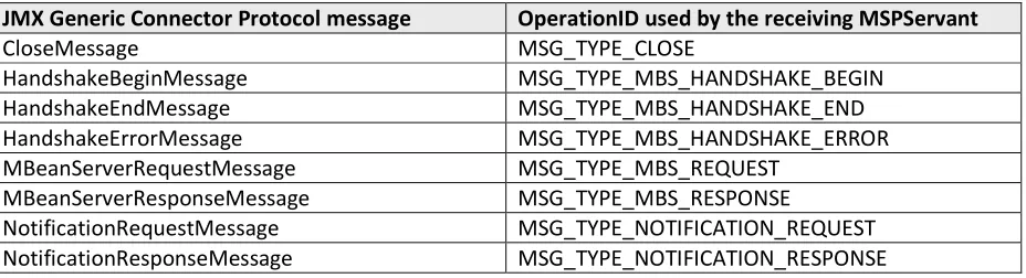
Furthermore, the Generic Connector specification describes the Generic Connector Protocol that implementations must follow in order to be able to interoperate with other implementations. This protocol defines the set of messages exchanged between the server and the client sides of the
connection and the order in which they must be exchanged [18]. This protocol and the different types of JMX messages defined by the specification are further described in section 4.3.
These packages provide the interfaces that define the way the MSP Interconnect protocol handles the communications between a device service and its surrogate.
Interconnect as transport protocol
used. The most relevant interfaces for our implementation
• MSP IO package: within this package MSPSurrogateHostConnection inter
on the device service side of the connection, and t implemented by any device service
• Interconnect package: especially relevant to our implementation is the I
interface, which defines how the communication is handled on the surrogate side of the connection. Besides, the LivenessHandler interface defines the method to be used to make sure a device service is still alive.
• Messages package: this
type of messages and encoding/decoding functions, as well as the MSPServant interface for handling incoming messages
In order to establish a connection between
necessary to obtain first a connection between the service and the Surrogate Host can be uploaded and activated. This can be accomplished by using
supplying the URL of the Surrogate Host location. If the location of the Surrogate Host is known to the device service this URL can be supplied directly, otherwise
[image:31.595.94.500.453.712.2]of the discovery mechanism provided by
Figure
packages provide the interfaces that define the way the MSP Interconnect protocol handles the communications between a device service and its surrogate. Therefore, in order to use
Interconnect as transport protocol for the JMXMSP Connector implementation, these interfaces must be The most relevant interfaces for our implementation, grouped by package,
: within this package the MSPSurrogateConnection and
MSPSurrogateHostConnection interfaces define the methods used to handle the communication service side of the connection, and the MSPDeviceService interface has to be implemented by any device service.
: especially relevant to our implementation is the InterconnectSession interface, which defines how the communication is handled on the surrogate side of the connection. Besides, the LivenessHandler interface defines the method to be used to make sure a device service is still alive.
: this package includes MSP Message related interfaces defining the different and encoding/decoding functions, as well as the MSPServant interface for
messages through the connection it is attached to.
nnection between the BAN management service and its surrogate, it is first a connection between the service and the Surrogate Host
can be uploaded and activated. This can be accomplished by using a ServiceHostConne
supplying the URL of the Surrogate Host location. If the location of the Surrogate Host is known to the device service this URL can be supplied directly, otherwise the Surrogate Host can be located by means of the discovery mechanism provided by the MSP Interconnect protocol.
Figure 6. ServiceConnection and ServiceSurrogateConnection
packages provide the interfaces that define the way the MSP Interconnect protocol handles the in order to use the MSP
these interfaces must be , grouped by package, are presented here:
faces define the methods used to handle the communication he MSPDeviceService interface has to be
nterconnectSession interface, which defines how the communication is handled on the surrogate side of the connection. Besides, the LivenessHandler interface defines the method to be used to make sure
essage related interfaces defining the different and encoding/decoding functions, as well as the MSPServant interface for
and its surrogate, it is
first a connection between the service and the Surrogate Host so that the surrogate ServiceHostConnection and
Once the ServiceHostConnection has been established its registerSurrogate method can be used to obtain a ServiceSurrogateConnection. This
which is an instance of the device service to be registered.
surrogate so that it can be retrieved by the Surrogate Host upon registration. The surrogate is us packed for convenience in a Jar file and located in a web server.
Note that the ServiceHostConnection
and the Surrogate Host, whereas the ServiceSurrogateConnection is the connection between BANManagementService and the
connection classes see Figure 6.
When the device surrogate has been uploade activate method that will in turn create a ServiceCon
surrogate and the corresponding device service. Once the service has a ServiceSurrogateConnection the surrogate has a ServiceConnection, the service and its surrogate are ready to interact
messages defined by the MSP messages package
Connector in order to handle the JMX management operations ex MBeanServer and the MBeanServerSurrogate
[image:32.595.77.522.392.710.2]section 4.3 for more details.
Figure
Once the ServiceHostConnection has been established its registerSurrogate method can be used to obtain a ServiceSurrogateConnection. This method accepts as an argument an MBUService object, which is an instance of the device service to be registered. This object must provide the location of the surrogate so that it can be retrieved by the Surrogate Host upon registration. The surrogate is us packed for convenience in a Jar file and located in a web server.
Note that the ServiceHostConnection represents the connection between the BANManagementService and the Surrogate Host, whereas the ServiceSurrogateConnection is the connection between
the BANManagementSurrogate. For a UML representation of both
When the device surrogate has been uploaded, the Surrogate Host takes care of calling
activate method that will in turn create a ServiceConnection representing the connection between the surrogate and the corresponding device service. Once the service has a ServiceSurrogateConnection the surrogate has a ServiceConnection, the service and its surrogate are ready to interact
messages defined by the MSP messages package. This connection will be used by the JMXMSP the JMX management operations exchanged between the BAN MBeanServer and the MBeanServerSurrogate as specified by the Generic Connector Protocol
Figure 7. BAN management architecture overview
Once the ServiceHostConnection has been established its registerSurrogate method can be used to method accepts as an argument an MBUService object,
This object must provide the location of the surrogate so that it can be retrieved by the Surrogate Host upon registration. The surrogate is usually
BANManagementService and the Surrogate Host, whereas the ServiceSurrogateConnection is the connection between the
For a UML representation of both
d, the Surrogate Host takes care of calling the surrogate representing the connection between the surrogate and the corresponding device service. Once the service has a ServiceSurrogateConnection and the surrogate has a ServiceConnection, the service and its surrogate are ready to interact using the
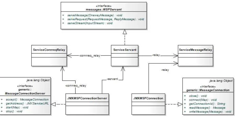
The JMXMSP Connector implementation mainly consists of the JMXMSPConnection,
JMXMSPConnectorServer and JMXMSPConnectionServer classes on the server side (MBU) and the JMXMSPConnector and JMXMSPConnectionSurrogate classes on the client side (Surrogate on the Surrogate Host). These classes make use of the different classes and interfaces provided by MSP and described above in order to use the MSP Interconnect as transport protocol.
The relation between these classes and the interfaces they implement is shown in Figure 7.
4.2
JMXMSP Connector Components
Once the BAN management service has a ServiceSurrogateConnection and the MBeanServerSurrogate service has a ServiceConnection and the surrogate has been activated, the MBeanServerSurrogate has to establish a new connection with the JMXMSPConnectorServer attached to the BAN MBeanServer to take care of the different JMX management operations.
This process can be divided in three different phases:
1. JMX connection setup: First a JMXMSPConnectorServer is created and attached to the BAN MBeanServer to listen for client connection requests. Then the MBeanServerSurrogate creates a JMXMSPConnector and initiates a connection handshake in order to establish a connection with the BAN MBeanServer. If the connection handshake succeeds, the connection to handle the JMX management operations between the BAN MBeanServer and the MBeanServerSurrogate has been successfully created. The BAN MBeanServer is then
2. Management phase: This phase is where a management application interacts with the BAN MBeanServer via the MBeanServerSurrogate by invoking operations on the different MBeans registered with the BAN MBeanServer, modifying their attributes, receiving notifications, etc. 3. JMX connection close-down: Either side of the connection can at any moment close the
connection established by sending a CloseMessage to the other end. This may be done, for instance if either side receives a message in the wrong order when performing the connection handshake [18]. After the connection has been closed the JMXMSPConnector should initiate again the JMX connection setup phase in order to be able to exchange management operations again.
The different components of the JMXMSP Connector involved in this connection setup and its usage, as well as their interactions are discussed in this section.
4.2.1 JMXMSPConnectorServer and JMXConnector
object, since they will be needed in order for the parent’s constructor.
Figure
The JMXMSPConnectorServer is created in the
constructor of its parent class (i.e. the GenericConnectorServer Map and the MBeanServer the JMXMSPConnectorServer contain two attributes: a MESSAGE_CONNECTION_SERVER made to this connector server and
wrapping for parameters whose deserialization requires special treatment. MESSAGE_CONNECTION_SERVER
when creating the JMXMSPConnectorServer As soon as the connector’s start
keep doing so until its stop method is called.
notification of class JMXConnectionNotification is emitted. The JMXMSPConnector defines the client side of the c
class and its implementation is similar to that of the JMXMSPConnectorServer. The constructor takes a JMXMSPConnectionSurrogate as an argument that is
when calling the GenericConnector
4.2.2 JMXMSPConnectionServer
The JMXMSPConnectionServer implements
which is the interface that specifies how the connector server establishes new connections with the clients. In our design an instance of JMXMSPConnectionServer is communicated to the
JMXMSPConnectorServer using the
, since they will be needed in order for the JMXMSPConnectorServer constructor
Figure 8. JMXMSPConnectorServer and JMXMSPConnector.
is created in the BANManagementService and its constructor
i.e. the GenericConnectorServer) with two parameters: an environment JMXMSPConnectorServer is attached to. This environment Map can MESSAGE_CONNECTION_SERVER attribute specifying how connections are made to this connector server and an OBJECT_WRAPPING attribute specifying the type of object
rapping for parameters whose deserialization requires special treatment. In our
SERVER attribute is set in order to use the JMXMSPConnectionServer JMXMSPConnectorServer.
method is called it will start listening for client connections, and will method is called. Every time a client connection is established or broken, a notification of class JMXConnectionNotification is emitted.
defines the client side of the connector. This class extends the GenericConnector class and its implementation is similar to that of the JMXMSPConnectorServer. The constructor takes a JMXMSPConnectionSurrogate as an argument that is used to set the MESSAGE_CONNECTION
GenericConnector’s constructor method.
JMXMSPConnectionServer
JMXMSPConnectionServer implements the MessageConnectionServer interface
which is the interface that specifies how the connector server establishes new connections with the an instance of JMXMSPConnectionServer is communicated to the
PConnectorServer using the MESSAGE_CONNECTION_SERVER attribute of the constructor’s JMXMSPConnectorServer constructor to call its
constructor calls the two parameters: an environment
This environment Map can attribute specifying how connections are attribute specifying the type of object
In our design, just the JMXMSPConnectionServer provided
ning for client connections, and will Every time a client con
![Figure 1. Conceptual model of a BAN [1]](https://thumb-us.123doks.com/thumbv2/123dok_us/1221984.646352/11.595.73.527.519.666/figure-conceptual-model-of-ban.webp)