Experimental study of a flexible and environmentally stable
electroadhesive device
GUO, Jianglong, BAMBER, Thomas, SINGH, Jatinder, MANBY, David,
BINGHAM, Paul <http://orcid.org/0000-0001-6017-0798>, JUSTHAM, Laura,
PETZING, Jon, PENDERS, Jacques <http://orcid.org/0000-0002-6049-508X>
and JACKSON, Michael
Available from Sheffield Hallam University Research Archive (SHURA) at:
http://shura.shu.ac.uk/17706/
This document is the author deposited version. You are advised to consult the
publisher's version if you wish to cite from it.
Published version
GUO, Jianglong, BAMBER, Thomas, SINGH, Jatinder, MANBY, David, BINGHAM,
Paul, JUSTHAM, Laura, PETZING, Jon, PENDERS, Jacques and JACKSON,
Michael (2017). Experimental study of a flexible and environmentally stable
electroadhesive device. Applied Physics Letters, 111 (25), p. 251603.
Copyright and re-use policy
See http://shura.shu.ac.uk/information.html
Sheffield Hallam University Research Archive
Experimental study of a flexible and environmentally stable electroadhesive device
J. Guo, T. Bamber, J. Singh, D. Manby, P. A. Bingham, L. Justham, J. Petzing, J. Penders, and M. Jackson
Citation: Appl. Phys. Lett. 111, 251603 (2017); View online: https://doi.org/10.1063/1.4995458
View Table of Contents: http://aip.scitation.org/toc/apl/111/25
Published by the American Institute of Physics
Articles you may be interested in
Chemical vapour deposition of freestanding sub-60 nm graphene gyroids
Applied Physics Letters 111, 253103 (2017); 10.1063/1.4997774
Electrically driven quantum light emission in electromechanically tuneable photonic crystal cavities
Applied Physics Letters 111, 251101 (2017); 10.1063/1.5008590
Magnetoelectric write and read operations in a stress-mediated multiferroic memory cell
Applied Physics Letters 110, 222401 (2017); 10.1063/1.4983717
Use of micro-photoluminescence as a contactless measure of the 2D electron density in a GaAs quantum well
Applied Physics Letters 110, 262104 (2017); 10.1063/1.4985439
Liquid metal actuator driven by electrochemical manipulation of surface tension
Experimental study of a flexible and environmentally stable electroadhesive
device
J.Guo,1,a)T.Bamber,1J.Singh,2D.Manby,3P. A.Bingham,2L.Justham,1,a)
J.Petzing,1J.Penders,2and M.Jackson1
1
The Wolfson School of Mechanical, Electrical and Manufacturing Engineering, Loughborough University, Loughborough, Leicestershire LE11 3TU, United Kingdom
2
Materials and Engineering Research Institute, Sheffield Hallam University, City Campus, Sheffield S1 1WB, United Kingdom
3
Aylesbury Automation Limited, Aylesbury HP20 1DQ, United Kingdom
(Received 11 July 2017; accepted 6 December 2017; published online 18 December 2017)
Electroadhesion is a promising adhesion mechanism for robotics and material handling applications due to several distinctive advantages it has over existing technologies. These advantages include enhanced adaptability, gentle/flexible handling, reduced complexity, and ultra-low energy consumption. Unstable electroadhesive forces, however, can arise in ambient environ-ments. Electroadhesive devices that can produce stable forces in changing environments are thus desirable. In this study, a flexible and environmentally stable electroadhesive device was designed and manufactured by conformally coating a layer of barium titanate dielectric on a chemically etched thin copper laminate. The results, obtained from an advanced electroadhesive “normal force” testing platform, show that only a relative difference of 5.94% in the normal force direction was observed. This was achieved when the relative humidity changed from 25% to 53%, tempera-ture from 13.7C to 32.8C, and atmospheric pressure from 999 hPa to 1016.9 hPa. This environ-mentally stable electroadhesive device may promote the application of the electroadhesion technology.VC 2017 Author(s). All article content, except where otherwise noted, is licensed under
a Creative Commons Attribution (CC BY) license (http://creativecommons.org/licenses/by/4.0/).
https://doi.org/10.1063/1.4995458
Electroadhesion1 is a promising and potentially revolu-tionary adhesion mechanism for mobile robotics and materials handling applications. Examples of where electroadhesion is in use include electrostatic chucks,2electroadhesive grasping of delicate objects3and fibrous materials,4climbing,5and perch-ing6robots. This is due to certain advantages that electroadhe-sion has over other adheelectroadhe-sion mechanisms such as magnetic, pneumatic, and bio-inspired adhesion methods.7These advan-tages include enhanced adaptability, gentle/flexible handling, reduced complexity, and ultra-low energy consumption.8
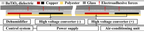
Electroadhesion is an electrically controllable and dynamic8 electrostatic attraction between an electroadhesive pad and a substrate, with 33 variables influencing the interfacial electroadhesive force.9These variables include voltage10,11and material properties such as relative permittivity,10–12pad geom-etry,13,14surface texture,15and environmental conditions.9,16A typical electroadhesion system contains four main parts, includ-ing an electroadhesive pad, a power supply, a control system, and a substrate, as can be seen in Fig.1. The electroadhesive force is generated by high-electric-field induced polarization or electrostatic induction depending on the material type.7
Environmental conditions can cause material properties (such as dielectric strength, permittivity, and resistivity) to change and therefore also the polarization properties. Among the environmental factors, Monkman17 concluded that only temperature and humidity have a noticeable effect on the electroadhesive force. Savioli et al.18 discovered that
different shear forces were obtained over three different days with differing temperature and humidity profiles. Guoet al.9 demonstrated that unstable normal electroadhesive forces were achieved in different ambient environments. Such vari-ability may hinder the wider application of electroadhesion technologies. An environmentally stable electroadhesive device is, therefore, needed and defined here as an electroad-hesive device that can produce stable electroadelectroad-hesive forces in changing temperature, relative humidity, and ambient pressure profiles.
[image:3.612.319.556.676.730.2]To address the environmental instability of current elec-troadhesive pads, Guoet al.16 implemented an environmen-tal adaptive electroadhesive actuator that could produce robust electroadhesive forces at different humidity levels. An empirical relationship between the minimum voltages needed to grip a known material and varying humidity lev-els, however, must be obtained and embedded in the control loop for the electroadhesive end effector to adjust the voltage output for different humidity levels. If a humidity level is not previously included in the empirical relationship, the end effector will not be able to output the right voltage to suc-cessfully grip the material.15It has to be noted that various
FIG. 1. Schematic diagram of a typical electroadhesion system. a)Authors to whom correspondence should be addressed: guojianglong9085@
sina.com and [email protected].
0003-6951/2017/111(25)/251603/4 111, 251603-1 VCAuthor(s) 2017.
experiments, however, are needed to obtain reasonably robust and comprehensive empirical relationships between the applied voltage and environmental factors (such as tem-perature, relative humidity, and ambient pressure) to cali-brate the voltage adjustment based on the information feed from the sensors, which is not cost-effective.
An alternative method is to coat electroadhesive pads with materials that are less sensitive to environmental varia-tions, thus producing stable electroadhesive properties in changing environments. In this way, the troublesome com-pensation/calibration procedure aforementioned can be elim-inated. There is, however, little research concerning coating electroadhesive pads with materials that are less sensitive to environmental variations, thus producing stable electroadhe-sive properties in changing environments.
This study reports the development and experimental characterization of an environmentally stable electroadhe-sive pad. Previous studies showed that improved perfor-mance, including greater adhesive forces and quicker release characteristics, was achieved by using a barium titanate (BaTiO3) coated electroadhesive pad.
19
Inspired by the fact that the dielectric constant of BaTiO3changes little in
differ-ent ambidiffer-ent environmdiffer-ents,19the studied environmentally sta-ble, flexista-ble, and lightweight electroadhesive pad was made from a chemically etched thin copper laminate (UK Insulations Ltd., UK) and a BaTiO3 dielectric (dielectric
constant of 8, Applied Technologies, Inc., US). The copper laminate was a 20lm/23lm copper polyethylene-terephthalate (PET) bilayer.
The flexible and environmentally stable electroadhesive pad manufacturing process consists of five major steps. These steps are similar to the electroadhesive pad manufac-ture procedures published previously14 except that the dielectric coating and degassing/curing method were differ-ent. First, an A4 sized 43-lm-thick copper-PET sheet was thoroughly cleaned and dried. A worm-comb geometry was then printed onto the copper side using a solid-ink (wax) printer (Xerox UK Ltd., UK). The worm-comb geometry was selected due to the fact that a previous experimental comparison of different geometries concluded that the worm-comb shape could bring slightly greater adhesive forces.14The dielectric strength and permittivity of the PET were 310 kV/mm and 3.2, respectively. The electrode width and gap were both 3.6 mm. The effective pad area was 180 mm198 mm. Second, the wax printed copper laminate was chemically etched, thoroughly cleaned, and dried. For the third stage, the laminate was clamped on a 10 mm alu-minium pad holder. A 50-lm-thick BaTiO3 dielectric was
then doctor-blade coated on the etched laminate using a micrometer adjustable film applicator (MTI Corporation, US) in a spray booth.
TheSq(root mean square height of the surface) value of the dielectric surface was 0.2460.01lm. To measure this, an Alicona InfiniteFocus G4 (Alicona, Austria) was used, with a20 objective. 10 different areas of the dielectric sur-face were measured. Sursur-face texture information of one area is presented in Fig.2(a). The BaTiO3dielectric was made of
BaTiO3 particles suspended in fluoropolymer. A FE-SEM
(field emission scanning electron microscopy, JSM-7800F, JEOL, Japan) image of the dielectric subsurface is shown in
Fig.2(b). The detector (X-Max 80, Oxford Instruments, UK) voltage and current were 20 kV and 4.3 nA, respectively. For the fourth stage, the coated electroadhesive pad and pad hol-der were placed in a vacuum oven (Fistreem International Ltd., UK) for degassing at room temperature for 10 min fol-lowed by curing at 120C for 20 min. Finally, the electroad-hesive pad was taken out of the oven and allowed to cool at room temperature for 24 h before testing. The prototype of the manufactured flexible and environmentally stable elec-troadhesive pad can be seen in Fig.2(c).
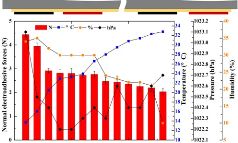
[image:4.612.317.558.54.322.2]Normal electroadhesive forces were measured using the advanced force measurement test rig and procedure pub-lished previously.9,10 The force tests were conducted over three days, and each test was repeated five times. A 15-time test was conducted previously to check the repeatability of the testing procedure and concluded that five times were enough to produce robust and repeatable results. It has to be noted that, however, these tests should be conducted under the condition that there is no degradation and dielectric breakdown of the electroadhesive pad. An air conditioner (Ecoair London, UK) and a dehumidifier (Ecoair London, UK), enclosed in an insulated foam sealed environmental chamber, were used to produce varying and controlled envi-ronmental conditions. As shown in Fig. 3, over the three days, the relative humidity changed from 25% to 53%. The room temperature changed from 13.7C to 32.8C. The atmospheric pressure changed from 999 hPa to 1016.9 hPa. Two high voltage converters (EMCO High Voltage Corporation, US), connected to a 0–5 V reference input DC power supply, were used to provide 3.6 kV to energize the electroadhesive pad. The electroadhesive pad was charged for 90 s before measuring the electroadhesive force between
FIG. 2. The BaTiO3dielectric coated electroadhesive pad: (a) surface tex-ture information (form removed) of one area of the BaTiO3dielectric sur-face, (b) SEM image of the dielectric, and (c) the proposed flexible and environmentally stable electroadhesive pad.
the BaTiO3 dielectric side of the pad and a glass plate
(Sq¼2.460.2 nm). The maximum normal electroadhesive force recorded was 20.1460.18 N, whereas the minimum was 19.0160.16 N.
In this study, a relative difference of only 5.94% was observed in the electroadhesive forces when the sample was exposed to a temperature difference of 19.1C, a relative humidity difference of 28%, and an atmospheric pressure dif-ference of 17.9 hPa, as shown in Fig.3. Please note that the relative difference is defined here as (maximumminimum)/ minimum100%.
The microstructures of the dielectric surface would influence the electroadhesive force obtainable.14As the aim of this study is to obtain the relationship between the electro-adhesive force and different environmental conditions, the surface microstructure of the proposed electroadhesive pad should be fixed. The same electroadhesive pad should, there-fore, be used to eliminate the variability of surface micro-structures. However, in order to show that the thickness of the dielectric layer will not affect the stable functional behavior of the proposed electroadhesive pad, a thinner
(30lm) BaTiO3 dielectric coated electroadhesive pad was
manufactured and tested at the same time. The results of this thinner electroadhesive pad showed that a relative difference of 6.13% was obtained in the electroadhesive forces under the same environmental conditions aforesaid. The result was close to the 50lm one. However, further tests using other coating thicknesses are needed to confirm that similar perfor-mance can be achieved using different coating thicknesses.
In this study, as the glass substrate was placed underneath the electroadhesive pad, the electroadhesive force was induced mainly by electric polarization. The electroadhesive force was measured when the BaTiO3dielectric was facing the substrate.
Previous results showed that the dielectric constant of BaTiO3
based materials was relatively stable from 10C to 50C.20In addition, the variation of the dielectric constant of BaTiO3
based materials was relatively small from 10% to 50%.21As shown in Fig.3, the relative difference in the electroadhesive force obtained was relatively small. It was assumed that this was due to the fact the coated BaTiO3 dielectric’s material
properties were quite stable in a range of ambient environ-ments,20,21 thus producing relatively stable electroadhesive forces. In order to experimentally verify this, two other elec-troadhesive pads, manufactured after the second manufactur-ing stage aforementioned, with the same electrode geometry and dimensions, were tested by facing the bare electrode
(electroadhesive pad coated with nothing) and PET (electroad-hesive pad coated with PET) side towards the glass substrate. For the electroadhesive pad coated with nothing, a relative dif-ference of 59.9% in the electroadhesive forces was observed when the pad was exposed to a temperature difference of 19.1C, a relative humidity difference of 25%, and an atmo-spheric pressure difference of 0.7 hPa, as shown in Fig.4. For the electroadhesive pad coated with PET, a relative difference of 117.6% in the electroadhesive forces was obtained when the pad was exposed to a temperature difference of 19.1C, a relative humidity difference of 24%, and an atmospheric pres-sure difference of 0.9 hPa, as shown in Fig. 5. However, a more in-depth understanding of the fundamental mechanism behind this should be conducted in the future.
[image:5.612.57.293.54.172.2]Previous results have shown a relative difference of 195.8% in the forces for a polyurethane coated electroadhe-sive pad exposed to a temperature difference of 0.7C, a rel-ative humidity difference of 21%, and an atmospheric pressure difference of 19.1 hPa.9Similarly, a relative differ-ence of 41.1% was observed in the forces for a polyimide coated electroadhesive pad which was exposed to a tempera-ture difference of 1.6C, a relative humidity difference of 12%, and an atmospheric pressure difference of 7 hPa.16The reported flexible and environmentally stable electroadhesive device presented here therefore demonstrates a step-change improvement in stability across a wide range of ambient operating conditions. This result suggests that significant
FIG. 3. Measured normal electroadhesive forces under changing environ-ments over three days.
[image:5.612.316.561.55.202.2]FIG. 4. The measured adhesive forces when the bare electrode side of the electroadhesive pad was facing the glass substrate.
FIG. 5. The measured adhesive forces when the PET side of the electroadhe-sive pad was facing the glass substrate.
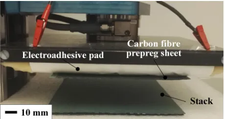
[image:5.612.316.559.598.744.2]improvements in electroadhesive devices may be possible through further investigations into alternative coating materi-als. This has the potential to greatly improve the capabilities of this adhesion method and increase its use in robotics and material handling applications. One possible industrial appli-cation is the robotic pick-and-place of carbon fibre prepreg sheets, as demonstrated in Fig.6, where a single layer of car-bon fibre prepreg sheet was picked up by the electroadhesive gripper from a stack.
The authors acknowledge support from the EPSRC Centre for Innovative Manufacturing in Intelligent Automation, under Grant Reference No. EP/IO33467/1, and support from Innovate UK under Project Reference No. 101549. In addition, the authors acknowledge use of the facilities and the assistance of Dr. Keith Yendal in the Loughborough Materials Characterisation Centre and Mr. Jagpal Singh in the Loughborough Metrology Lab.
1K. Rahbek, “Electroadhesion apparatus,” U.S. patent 2,025,123 (24
December 1935). 2
G. Shim and H. Sugai,Plasma Fusion Res.3, 51 (2008).
3J. Shintake, S. Rosset, B. Schubert, D. Floreano, and H. Shea,Adv. Mater.
28(2), 231–238 (2016). 4
G. J. Monkman,Int. J. Rob. Res.14(2), 144–151 (1995). 5
R. Liu, R. Chen, H. Shen, and R. Zhang,Int. J. Adv. Rob. Syst.10(36), 1–9 (2012).
6
M. Graule, P. Chirarattananon, S. Fuller, N. Jafferis, K. Ma, M. Spenko, R. Kornbluh, and R. Wood,Science352, 978–982 (2016).
7
J. Guo, L. Justham, M. Jackson, and R. Parkin, Key Eng. Mater.649, 22–29 (2015).
8T. Bamber, J. Guo, J. Singh, M. Bigharaz, P. A. Bingham, L. Justham, J.
Petzing, J. Penders, and M. Jackson, J. Phys. D: Appl. Phys. 50(20), 205304 (2017).
9J. Guo, T. Bamber, M. Chamberlain, L. Justham, and M. Jackson,J. Phys.
D: Appl. Phys.49(41), 415304 (2016). 10
J. Guo, T. Bamber, J. Pezting, L. Justham, and M. Jackson,Appl. Phys. Lett.110(5), 051602 (2017).
11K. H. Koh, M. Sreekumar, and S. G. Ponnambalam, Materials 7,
4963–4981 (2014). 12
C. Cao, X. Sun, Y. Fang, Q. Qin, A. Yu, and X. Feng,Mater. Des.89, 485–491 (2016).
13D. Ruffatto, J. Shah, and M. Spenko,J. Electrost.72(2), 147–155 (2014). 14J. Guo, T. Bamber, T. Hovell, M. Chamberlain, L. Justham, and M.
Jackson,IFAC-PapersOnLine49(21), 309–315 (2016). 15
J. Guo, M. Tailor, T. Bamber, M. Chamberlain, L. Justham, and M. Jackson,J. Phys. D: Appl. Phys.49(3), 35303 (2016).
16J. Guo, T. Bamber, M. Chamberlain, L. Justham, and M. Jackson,IEEE
Rob. Autom. Lett.2(2), 538–545 (2017). 17
G. J. Monkman, “Electrostatic techniques for fabric handling,” M.Sc. the-sis, University of Hull, 1987.
18L. Savioli, G. Sguotti, A. Francesconi, F. Branz, J. Krahn, and C. Menon,
Proc. SPIE9061, 906129 (2014). 19
Aylesbury Automation Limited, “Electroadhesive gripper,” UK patent application GB1608729.8 (18 May 2016).
20
D. Sitko, W. Ba˛k, B. Garbarz-Glos, A. Budziak, C. Kajtoch, and A. Kalvane,IOP Conf. Ser.: Mater. Sci. Eng.49, 012050 (2013).
21
[image:6.612.60.290.54.176.2]J. Wang, B. K. Xu, S. P. Ruan, and S. P. Wang,Mater. Chem. Phys.78(3), 746–750 (2003).
FIG. 6. Electroadhesive grasping of a carbon fibre prepreg sheet from a stack.