Abstract— Shape optimization is numerically a very demanding process, where several traditionally separate numerical processes meet together in a heterogeneous multidisciplinary environment. Typical elements involved are (1) the optimizer itself that implements the selected search strategy, (2) the parameterization procedure that provides the bidirectional mapping interface between the 3D geometric shape of the object and a limited number of parameters that control the parametric model of the geometry, (3) the simulation program that provides the results of the simulated interaction between the object and its environment (such as finite element analysis, FEA), and (4) control procedures that monitor the overall workflow and invoke mutual application calls (process flows and data flows) and handle data mining as well as acceptance or rejection of individual instances of candidate designs which are numerically generated and analyzed. In this paper, the set-up of this complex process, combined with evolutionary optimization, is developed with the objectives of numerical flexibility, computational efficiency in terms of combining sequential and parallel execution of individual applications, and low-cost implementation within an unmanaged computer cluster based on the Windows Communication Foundation, WCF.
Index Terms— Shape optimization, distributed numerical workflow, parallelization, WCF cluster.
I. INTRODUCTION
In engineering practice, many objects exhibit technical behavior that strongly depends on the geometric shape of those objects. Among other ‘ingredients’, professional heritage in engineering practice also provides experience in terms of object shapes that are well- suited to perform certain tasks or to deliver required functionalities. This heritage has not been generated in a straight- forward process of objective- driven shape synthesis, but rather in an iterative manner of try-and-error sequences in the past. One cannot speak of direct shape synthesis based on functional requirements but rather of small, incremental improvements in modifying existing shapes based on successive
2
Manuscript received on …, 2009. This work was supported in part by the project 023-0231744-3113 of the Ministry of Science, Education and Sports of the Republic of Croatia.
D. Vucina and Z. Lozina are professors, I. Pehnec is assistant at the Faculty of Electrical Engineering, Mechanical Engineering and Naval Architecture, University of Split, Croatia, 21000 Split (385-21-305-969; e.mail: [email protected]).
engineering analysis. The former, direct functional synthesis, is generally still to be described as wishful thinking.
As illustrated in Fig.1, computer-aided shape synthesis essentially consists of the sequence:
A. Generating and proposing candidate shapes which might potentially deliver the required functionality B. Analysis (FEA, etc.) of candidate shapes for (1)
fulfillment of required functionality and (2) providing excellence measured in corresponding criteria and objectives
C. Systematic repeating of the procedure according to the optimizer’s search scheme
The problem of shape optimization can be defined as determining the shape of an object within given constraints such that the corresponding performance be optimal. In other words, provided that excellence criteria and metrics are known and constraint conditions are formulated, the problem is to synthesize the geometric shape such that the latter (constraints) are satisfied and the former (objectives) maximized. Obviously, in the mathematical model of the corresponding particular problem, both the constraints and the excellence criteria are functions which depend on shape.
Fig.1, Engineering synthesis vs. iterative analysis
Reverse Engineering with Shape Optimization
using Workflow-Based Computation and
Distributed Computing
Fig.2. Parameterization of geometry for shape optimization
Shape optimization is essentially infinite dimensional since in general shape is a continuous entity. Since numerical optimization methods deal with a finite number of optimization variables, a mapping that defines the relationship between the continuous shape and a finite number of parameters is necessary.
This is referred to as shape parameterization, and after the geometry has been parameterized, the standard formulation, [1], [2], of optimization problems can be applied:
min { f(x) } (1) g(x) ≤ 0 (2) where x is the n-dimensional vector of shape optimization variables, f the k-dimensional vector of objective functions in the multi-objective formulation (multi- dimensional criteria space), and g the p-dimensional vector of inequality constraint functions (equality constraints can also be considered in this form).
This model with shape parameters as optimization variables extends the applicability of standard iterative numerical optimizers, both gradient and non-gradient including evolutionary, to shape optimization problems. This means that the optimization process starts with an initial solution (in this case initial shape) which, by means of the optimization algorithm, evolves into the respectively optimal geometric shape within the scope of the given set of constraints and steered by the given (typically multi-objective) excellence criteria.
A number of different approaches to parameterizations for shape optimization are reported in the literature, [3]- [15]. These approaches include contours defined by point sets, parametric curves and surfaces, superposition of component shapes, parametric CAD formulations and other. An efficient parameterization should ideally use few shape variables, be
capable of representing global and local shape accurately, allow simple communication of geometric updates to CAD and FEA, and allow easy detection of topologically, geometrically or dimensionally invalid shapes or those that physically interfere with other objects.
In this paper, genetic algorithms (GA), [16]- [19], are used for the actual shape optimization, (1)-(2). The constraints (2) and objective functions (1) are evaluated by applying finite- element analysis (FEA), [20].
Although shape optimization can also be approached by the micro-level approach and methods used in topology optimization that remove discrete portions of material or change properties in individual parts of the object (e.g. ‘cells’), the macro-level approach of applying parametric geometric entities is in many cases more fruitful. This especially applies to cases where the design starts from some initial idea of shape, while the former approach can be applied to the ‘raw block of material’ without any initial geometric assumptions.
II. FORMULATION OF THE PROBLEM
The iterative procedure of analysis of successive candidates in Fig.1 is the core of shape synthesis and shape optimization. However, it is neither a simple nor a straight-forward process, and certainly not numerically moderate. A number of essential elements have to be provided for:
1. Representation and coding of 3D geometric shape: efficient parameterization in geometric modeling, 2. Numerically efficient generation of new (feasible but
also infeasible) candidate shapes,
3. Numerically adequate and effective simulation procedures that implement the analysis of candidate shapes and their respective performance in interaction with the environment (FEA, Fig.3) 4. Management of this heterogeneous numerical system
including: verification of geometric and technical feasibility, acceptance or rejection of individual instances of geometric objects, orchestration of individual applications with mutual calls and exchange of updated geometric information
Beyond the requirements 1.- 4., the system should preferably be assembled from existing applications used by the engineering designer in his / her practice, such as common geometric modeling software (GM), common finite element analysis software (FEA), etc.
Fig.3. Overall numerical implementation of shape optimization
However, this implies that a management system has to be developed to:
- handle sequential and parallel executions of individual applications,
- synchronize the exchange of updated geometric information, transform it into the native formats of individual applications in the workflow and propagate it to proper destinations in respective applications’ I/O files
- make decisions: which numerically generated designs should be accepted or rejected, which new regions in the shape optimization search space to explore, which instances of applications that failed (due to infeasibility in terms of not satisfying constraint conditions or due to invalid geometry) to dismiss, assess overall excellence, etc.
Therefore, a standard managed computer cluster running a scalable integrally inclusive (items 1.- 4.) application is not suitable in this case. This paper implements the opposite approach: a computer cluster is set-up to run different applications on different computers on the as-needed basis. These applications can dynamically make mutual calls to other applications in the workflow which includes sequential, and parallel entities as well as branching, and exchange data. This is implemented flexibly and dynamically as the instances of individual applications participate only as long as necessary to perform their respective assignments and deliver their respective results. Hence, the system acts as an orchestra of existing specialized applications for different tasks needed in the overall optimum shape design (Fig.3) which provides an efficient and low-cost computational implementation of the complex multidisciplinary problem of optimum shape design.
In fact, the layout of the numerical implementation in this paper is not a scalable all-inclusive application built to run on a managed computer cluster, but rather a distributed-computing macro-application developed for this
workflow to encapsulate a joint operation of a heterogeneous system of different applications. It is designed generically to assume no specific requirements on applications that participate in the cluster workflow, neither in terms of management of mutual calls nor in terms of data exchange. With the system as developed here, no application-specific requirements are necessary (e.g. return values), the developed control & monitoring programs only use each application’s output files to find out about the validity of its execution, and data are communicated via data mining in native formats of respective files. Simulated menu keystrokes and generated batch mode commands in the master process of the workflow make it possible to externally invoke any application. This flexibility is provided in the sense that the workflow itself is adaptive and can dynamically change (reconfigure the workflow sequences) during execution.
III. NUMERICAL IMPLEMENTATION In order to implement the above numerical processes, the workflow includes: (1) an optimizer developed based on MATLAB [22] and additional scripts in C#, (2) FEA analysis implemented in ADINA, [21], (3) control and workflow management scripts implemented in C#.
The optimizer is a version of genetic algorithms adapted to operate on shape variables, although other optimizers can be applied in the framework of Fig.3 as well. The corresponding phenotype corresponds to the physical shape to be numerically generated by means of the selected shape parameterization, in particular the control points of parametric curves, and the genotype contains the coding of their coordinates in each instance’s chromosome.
In order to enhance numerical efficiency in Fig.3, the FEA simulator (Fig.5) can be implemented in an array of instances running on parallel computers in an ad-hoc unmanaged cluster.
Fig.5. Basic structure of the FEA simulator
The reason for increasing the computational capacity of the simulator application in Fig.3 by parallelizing it and launching multiple instances asynchronously is the fact that the analysis in Fig.5 consumes by far the most computation time in the overall shape optimization process.
The cluster is here developed based on the “.net“ technology, in particular the WCF- Windows Communication Foundation that facilitates the set-up of the workflow and the client – server communication. In fact, the cluster specialized for shape optimization as developed here is centered around the problem that is being solved, instead of, as typically, around the computationally scalable application. Several different applications (CAD, FEA, Control) are typically necessary in the shape optimization problem, therefore a system of different applications need to process different aspects of the same problem. Therefore, a cluster configuration with a single client and many servers is developed, whereby the servers expose different services necessary in shape optimization, listen for requests from the client, and provide the services when requested.
The servers run listener scripts and provide services of external, locally installed applications, which in this case include MATLAB scripts and ADINA FEA simulators which can be invoked by remote calls from the client, communicated by means of WCF. The client that runs and integrates the overall shape optimization processes can make asynchronous calls to a number of parallel servers.
Fig.6, Single client – many servers configuration for the WCF shape optimization workflow
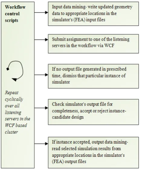
The servers handle the computer-time and numerically intensive simulations in parallel and asynchronously and return the results to the client as they complete their respective assignments. Based on the simulation results returned, the optimization logic within the client makes the decisions on how to proceed with the optimum search and generates the new set (next generation) of assignments to be submitted to the servers, Fig.6. The control scripts developed for the workflow are in charge of the activities in Fig.7. The computational implementation of the workflow as shown in Figs. 6 and 7 is in development for increased performance.
Input file
Analysis data:
- Geometry: points, lines, surfaces, bodies - Discretization, meshing:
mesh, nodes, elements, - Boundary conditions
Pre-processor
Processor:
Solve discretized physical model
Fig.7, Duties of the control scripts developed for the shape optimization workflow within WCF
IV. TEST PROBLEM
The shape optimization workflow is finally applied to the shape optimization problem of synthesis of the airfoil for wind- turbine blades. A specific parameterization is developed for this purpose where individual Bezier curves (4) are chained (3) together (piecewise curves), and C1 continuity is imposed by generating additional control points at joint segments, [23],
⎪ ⎪ ⎭ ⎪ ⎪ ⎬ ⎫
⎪ ⎪ ⎩ ⎪ ⎪ ⎨ ⎧
⇒
) ( ...
) (
) (
2 1
x p
x p
x p
P
n
(3)
where P is the set of parameters that defines both the original control points and implicitly the ones generated for inter-segment continuity, and pi(x) are the chained piecewise
curves.
The positions of the original control points correspond to the respective shape optimization variables. The developed parameterization provides significant adaptive capacity since the degrees of individual piecewise curves and the respective number of chained curves, which defines the structure and size of the control points set, can be chosen at run-time.
i i n n
i
i i
n
i n
i u u
i n u
B
u P P
P ⎟⎟⋅ ⋅ − ⋅
⎠ ⎞ ⎜⎜ ⎝ ⎛ = ⋅
= −
=
=
∑
∑
( ) (1 ) )(
0 0
, (4)
[image:5.595.59.293.51.333.2]
Fig. 8. shows an example of shape synthesis of an initial, randomly generated airfoil which is shape- optimized using the criterion of the maximum integral lift / drag ratio max { cl / cd } (5) as the objective function (excellence criterion) in shape synthesis, which leads to the optimized shape such as the one in Fig. 8 (b).
Fig. 8. Shape optimization of the airfoil, intermediate (infeasible) shape (a) and optimized shape (b)
V. CONCLUSION
REFERENCES
[1] J. Arora, Introduction to Optimum Design, McGraw-Hill: New York 1989.
[2] S.S. Rao, Engineering Optimization, Wiley Interscience: New York 1996
[3] M.H. Imam, “Three dimensional shape optimization”, Int. J. Numer. Meth. Engrg., vol. 18, 1982, pp. 661-677
[4] V. Braibant, C. Fleury, “Shape optimal design using B-splines”, Comput. Meth. Appl. Mech. Engrg., vol. 44, 1984, pp. 247-267 [5] G. N. Vanderplaats, “Approximation Concepts for Numerical
Airfoil Optimization”, NASA Technical Paper 1370, 1979 [6] G. N. Braibant, C. Fleury, “An approximation-concepts
approach to shape optimal design”, Comput. Meth. Appl. Mech. Engrg., vol. 53, 1985, pp. 119-148.
[7] V. Braibant, C. Fleury, “Shape optimal design. A CAD-oriented formulation”, Engineering with computers, vol. 1(4), 1986, pp. 193-204
[8] M. Pourazady, Z. Fu, “An Integrated Approach To Structural Shape Optimization”, Computers & Structures, vol. 60(2), 1996, pp. 279-289.
[9] M. Zhou, N. Pagaldipti, H.L. Thomas, Y.K. Shyy, “An integrated approach to topology, sizing, and shape optimization”, Struct Multidisc Optim, vol. 26, 2004, pp. 308–317
[10] K. Saitou, K. Izui, S. Nishiwaki, P. Papalambros, “A Survey of Structural Optimization in Mechanical Product Development”. Transactions of the ASME, vol. 5, 2005, pp. 214-226
[11] R.T. Haftka, R.V. Grandhi, “Structural shape optimization– a survey”, Comp. Meth. Appl. Mech. Engrg., vol. 57, 1986, pp. 91–106
[12] J.A.Samareh, “A Survey Of Shape Parameterization Techniques”, CEAS/AIAA/ICASE/NASA Langley International Forum on Aeroelasticity and Structural Dynamics, 1999, Williamsburg. Also, NASA/ CP-1999-209136, 1999, pp. 333-343.
[13] J.A. Samareh, “Geometry Modelling and Grid Generation for Design and Optimization”, ICASE/LaRC/NSF/ARO Workshop on Computational Aerosciences in the 21st Century, 1998, pp.1- 19
[14] L. Dai, Y. Gu, G. Zhao, Y. Guo, “Structural Shape Optimization based on Parametric Dimension-Driving and CAD Software Integration”, 6th World Congress on Structural and Multidisciplinary Optimization, Rio de Janeiro, 2005
[15] G. Farin, Curves and Surfaces for Computer Aided Geometric Design (2nd edn). Academic Press: New York, 1993.
[16] D.E. Goldberg, Genetic Algorithms in Search, Optimization and Machine Learning, Addison Wesley, 1989
[17] K. Deb, Multi-Objective Optimization using Evolutionary Algorithms, Wiley and Sons: New York, 2001
[18] K. Deb and T. Goel. “A Hybrid Multi-Objective Evolutionary Approach to Engineering Shape Design”, First International Conference on Evolutionary Multi-Criterion Optimization, pp. 385-399. Springer-Verlag, Lecture Notes in Computer Science No. 1993, 2001
[19] K. Deb and T. Goyal. “Multi-Objective Evolutionary Algorithms for Engineering Shape Design”, KanGAL report 200003, Indian Institute of Technology, Kanpur, India, 2000 [20] R.D.Cook, D.S. Malkus, M.E. Plesha, R.J. Witt, Concepts and
Applications of Finite Element Analysis, Wiley and Sons: New York, 2002
[21] Adina, ADINATM 8.3 User interface and command reference manual, Adina R&D Inc, 2005
[22] modeFRONTIER, www.esteco.com