Reprinted from:
Proceedings of
2nd ACM Symposium on
Operating Systems Principles
Patel
R
a.i in i
M.
BASIC I/O HANDLING ON BURROUGHS B6500
Rajani M. Patel
Burroughs CorporationPasadena,
California
Summary: The approach to processing basic Input/Output in B6500 hardware design
and software implementation is discussed in this paper. Hardware I/O structure
necessary to the understanding of the approach is described first. The
represen-tation of the I/O queue and the algorithms used in handling I/O requests are
described in detail to emphasize the ease with which the I/O handling portions of
the executive system may be modified to suit any installation. Some of the I/O
tables for coordinating I/O activity are discussed. The concept of asynchronous
processes running as extended arms of the executive system is discussed and the
implementation of it for updating status of peripheral units, for handling I/O
errors, etc. is described. The usage and implementation of I/O related events
and software interrupts is discussed. The locking concept is presented. Finally,
the complete I/O initiation and completion cycle is described. The description
throughout this paper is based on the actual working system implemented with
language ESPOL -an extended ALGOL language used for writing executiv~ systems.
Some of the special language constructs pertinent to I/O handling are illustrated.
INTRODUCTION
The B6500 stack organization is designed for process switching and makes its
operation efficient for a multiprogramming/multiprocessing environment. To
com-plement the hardware design, events and queues are implemented in the software for
inter-process communication and deactivation and activation of a process during an
I/O cycle or because of preemption.
This paper describes how the basic I/O needs are satisfied in such a process-orientedenvironment.
The term 'process' in B6500 System is easy to understand if it is
remembered that the process has its own stack to run. Excep~ for some minor
imple-mentation details, all processes, whether belonging to a Master Control Program (MCP)
or an user program, are treated in the same manner. The only meaningful way to
identify whether a process is a 'MCP process' or an 'user process' is to recognize
the function (MCP or User) for which the process stack assignment is made. The MCP,
itself, is represented by a single process (which loops around looking for something
to do) when there is nothing to do or it extends itself into a number of independent
MCP processes, when the need arises to serve more system functions.
Much of the ground work is done in explaining B6500 design elsewhere by Hauck and
Dentl, Hillegas2, and Cleary3. Hence the preliminary discussion is bypassed and
only I/O related details are presented here.
I/O HARDWARE
Figure 1 gives a typical B6500 I/O facility. The system uses peripheral control
multiplexors and associated peripheral controls for transferring data between memory
and peripheral equipment. Once the multiplexor receives an I/O command (from a
processor), the transfer of data takes place independent of the processors. One or
two multiplexors may be attached to a system. Anyone of the processors (in amultiprocessor
MUL TIPLEXOR
Up to 20 peripheral control units can be connected to each I/O multiplexor. This
may include up to 5 subsystems, which use multiple control units (2 to 4 control
units per subsystem). In a B6500 system, up to 256 peripheral units (numbered
from 0 to 255) can be designated. The multiplexor also includes a time-of-day
clock and character translators.
The multiplexor uses data-switching channels for data transfer, a word buffer for
each control which is transferring data. Each multiplexor can contain from 4 to
10 channels. These data-switching channels are 'floating' so that any available
channel may be used for any of the devices connected to the multiplexor. Thus a
single multiplexor can handle up to 10 data operations simultaneously. The
assign-ment of the data-switching channels is performed by the multiplexor; upon initiation
of an operation, the hardware assigns an available channel to the operation. Amultiplexor
service cycle (time 1.2 micro-seconds) is required each time an I/O
control requires attention. During each service cycle 16 bits (2 bytes) are
trans-ferred between the multiplexor and high-speed device I/O controls e.g., a disk or
tape control, etc. All other controls transfer 8 bits per cycle.
The multiplexor also includes other facilities, but they are not described here,
as they are not relevant to this discussion.
1/0 WORD FORMATS
The standard B6500 data and control words are 51 bits long (actually 52 bits
including a bit for memory parity checking). The 'tag' in the first three bits
determines the type of word. The remaining 48 bits are data or control information.
Figure 2 illustrates the formats of the words used for I/O operation. The M and Z
fields of Unit word (figure 2a) set the option of having all active multiplexors or
a particular multiplexor respond to the processor. The FC field contains a function
code defining the operation.
Typical functions are interrogate peripheral status, report a path to a unit,
initiate an I/O operation and report details (result descriptor) of a completedoperation.
The area descriptor (figure 2b) specifies the base address of the main
memory area and the length of the data.
The I/O control word (figure 2c) contains a standard control field and a unit control
field unique for each peripheral control. The standard control field has bits for
the standard options like Read/Write, memory inhibit, translate, frame length, memory
protect, backward transfer, etc. The I/O control word is in the first word of the
area addressed by the area descriptor.
The result descriptor (figure 2d) has the memory address at which the I/O is ter-minated,
the unit number and the error field. The error field is subdivided into a
standard error field and a unit error field, unique for each peripheral control.
Some of the errors indicated in standard I/O error field are memory parity error,
memory address error, I/O descriptor error, not ready condition or busy condition.
The least significant bit (Hardware Exception bit) is turned on if any error is
encountered in the I/O operation.
(a) UNIT WORD
(b) AREA DESCRIPTOR
STANDARD CONTROL UNIT CONTROL
7 36 5 0
(c) Vo CONTROL WORD
MEMORY ADDRE&& 7 2&
Cd) RESULT DESCRI PTOR
I/O WORD FORMATS
I/O OPERATORS
There are two processor operators for communicating between the processors andmultiplexors.
The SCAN IN operator is used to interrogate or to read from a
multi-plexor, and the SCAN OUT operator transmits to the multiplexor.
The
SCAN IN operator is available in ESPOL language as an intrinsic procedure of
type REAL, with the 'unit word' as its parameter. Some of the SCAN IN functions
are described here.
a. Interro ate Peri heral Status. In order to minimize both software overhead
and system response time, the ready not-ready status of each peripheral is made
available in a row of bits called READY-STATUS vector. Since the system may contain
256 units, this vector is broken into eight words, each containing the status-bitsfor
32 units.
b. Interrogate Peripheral Unit Type. Thi.<; function returns the value of the
unit-type code. Each kind of peripheral unit has a unique type code.
c. Interrogate I/O Path. This function determines if there is a path (an
available control and a channel) through which an I/O operation can be initiated
on the unit specified. The path can be checked for all multiplexors (for a unit
which is common to both multiplexors) or a particular multiplexor. The returned
value indicates which multiplexor(s) contain such a path.
d. Read Result Descriptor. This function returns a result descriptor word
from the specified multiplexor. The result of a completed I/O stays in the multi-plexor
buffer until the result is read, at which time the associated channel isreleased.
One of the functions of the SCAN OUT operator is to initiate an I/O.
privileged operation and can only be executed in control state.
This is a
The INITIATEIO intrinsic procedure has two parameters. The first parameter contains
the unit number and the multiplexor designation and the second parameter is the
area descriptor.
SOFTWARE DESIGN
Burroughs'
philosophy of using higher level languages for writing executive programs
is successfully extended to B6500 software. The language ESPOL (Executive System
Programming Oriented Language) used for writing the MCP is an extension of ALGOL
and is itself written in the B6500 Extended ALGOL. Special language constructs
take full advantage of B6500 design. The design and use of this language has
simplified the I/O management and made it possible to implement a well-organized
structure in a very short time.
lANGUAGE FACiliTIES
Some of the features of ESPOL are discussed by Cleary3: however, the following
features are presented here to emphasize the simplicity of I/O handling. It is
beyond the scope of this paper to include all language constructs, but some sample
declarations and statements are illustrated in figures 3 and 4. A complete I/O
queue declaration including associated algorithms is given in figure 3. This is
described in detail in the section on I/O Queue. Declarations and statements given
in figure 4 are only for illustration and do not follow any logic.
FIELD identifiers are used for manipulating a bit or a group of bits in a word.
A LAYOUT is a series of fields, useful in making up words of various formats.
REFERENCE variables and arrays point to queue entries. DEFINE identifiers
repre-sent text and the appearance of such a variable in the program is equivalent to
the appearance of the text. A DEFINE identifier may also be parameterized, in
which case the actual parameters replace the formal parameters in the related text,
The statements show methods of referencing items in a queue and invoking queue
algorithms. Intrinsic procedures are provided for special hardware operators.
Event handling and asynchronous processes are discussed in the later sections.
I/O QUEUE
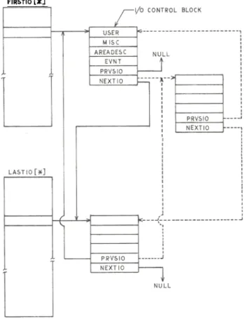
The ESPOL declaration for the I/O queue is given in figure 3 and it is represented
pictorially in figure 5. The I/O queue is a queue array (IOQUE). It is implicit
in the queue declaration that FIRSTIO becomes the queue head array with the total
number of units as its size. An explicit declaration is made for the array LASTIO
to represent queue tails. Each word in FIRSTIO array and LASTIO array points
respectively to a head and a tail entry of a queue belonging to a particular unit.
The unit number is used as an index.
The form and content of each queue entry is described, in a manner nearly identical
with a procedure's formal parameter description. The last two items (PRVSIO and
NEXTIO) of the queue entry block, following the colon, are invisible (cannot be
referenced) outside of the queue declaration. As the names suggest, these are the
pointers used for linking the entries in a queue and they can be manipulated at
only one place, namely, the queue algorithm. The identifiers declared within the
parenthesis take on the index depending on the order in which they are declared
and are used for referencing items of a queue entry block.
FIELD UNITNO=16:8, UN I TMPXD=4:4, UNITMPXI=O:1; LAYOUT 10PATHWORD(UNITNO, UNITMPXD, UNITMPXI);
CtMoiENT WORD FORMAT FOR INTERROGATING I/O PATH; REAL U, USERY, MISCV;
REFERENCE 10CB; EVENT 10EVENT;
DEFINE MAGTAPE(TYPE)=TYPE>13 AND TYPE<15 OR TYPE>29#; ARRAY 10AREA[*];
REFERENCE ARRAY LAST 10 [*]; ARRAY DUMMYIOQUE (*]; DEFINE
FIRSTIOU=FIRSTIO[INDKX)#, COMMENT INDEX IS QUEUE HEAD INDEX; LASTIOU=LASTIO[lNDEX)#;
QUBUE ARRAY 10QUE:FIRSTI0[*) (USER,MISC,AREADESC, EVNT :PRVSIO,NEXTIO); VALUE USER,MISC,AREAOESC,EVNT,PRVSIO,NEXTIO; REAL USER, MISC;
EVENT EVNT;
REFERENCE AREADESC,PRVSIO,NEXTIO;
COMMENT FOLL(1tIING SH(1tIS S~E I/O QUEUE CONSTRUCTS; 10CB:=IOOUE(USERV,MISCV,REFERENCE( 10AREA), IOEVENT);
C(M.\ENT INVOKES ALLOCATE ALGORITHM AND STORES ENTRY DESCRIPTOR IN 10GB;
10QUE[U] :=IOCB; COMMENT INVOKES INSERT ALGORITHM; 10QUE[U]:=IOOUE(USERV,MISCV,REFERENCE(IOAREA),IOEVENT;
COMMENT INVOKES BOTH ALLOCATE AND INSERT; MISCV:=MISC @(IOCB); COMMENT RETRIEVES MISC ITEM;
DELINK(IOQUE, IOCB,U); COMMENT DELINKS ENTRY; USING
ALLOCATE IS REFERENCE(OUMMYIOQUE & ARRAYDESCU3,6,GETAREA(6))): TO INSERT, COMMENT QUEUE IS ARRANGED ON FIRST-IN-FIRST-OUT BASIS; BEGIN
IF LASTIOU = NULL THEN
BEGIN COMMENT QUEUE IS EMPTY;
LASTIOU:=FIRSTIOU:=ENTRY;COMMENT ENTRY IS A DESCRIPTOR POINTING TO I/O CONTROL BLOCK; NEXTIO @(FIRSTIOU):=PRVSIO @(FIRSTIOU):=NULL;
END ELSE
BEGIN C()IMENT PUT ENTRY AT TAIL OF QUEUE; PRVSIO @(ENTRY):=LASTIOU ;
NEXTIO @(LASTIOU):=ENTRY; LASTIOU:=ENTRY;
NEXTIO @(ENTRY) := NULL; END.,
END INSERTION OF ENTRY IN QUEUE:
SOME ~ DECLARATIONS AND STATEMENTS
Fig.
F1g.3. I/O QUEUE DECLARATION
The algorithms for manipulating the queue are essentially part of the queue declara-tions.
Two typical algorithms called ALLOCATE and INSERT are shown in figure 3.
The statements for invoking algorithms are shown in a separate section in figure 4.
The ALLOCATE algorithm allocates an area of main memory (in this case, 6 words) for
a queue entry. ALLOCATE is invoked implicitly by the construct shown in figure 4,
which also inserts the actual parameters in the entry block. Figure 5 shows a
typical I/O control block (IOCB). Item references (the "@" constructs) are used
for referencing information in the entry block. A sub-level memory allocation
routine, GETAREA is used for allocation of I/O control blocks.
The INSERT algorithm inserts an entry into the queue. The algorithm shown in
figure 3 is a simple one serving on a first-in-first-out basis. Figure 5 shows
the linking mechanism and the queue structure. The words ENTRY and INDEX in the
algorithm refer to the entry and the queue head index passes implicitly by
algorithm-invoking statements. By using a priority as a field in the USER item
of the IOCB, the algorithm can be modified to achieve specially tailored I/O
handling at a particular system installation. The DELINK algorithm (not
illus-trated) removes an entry from the queue. Dotted lines in figure 5 show the links
of a removed entry.
In addition to the I/O queue, there is a queue array called WAITCHANNELQUE formultiplexors.
An entry of this queue has a unit number for a unit waiting for a
path and the two links for previous and next waiting unit.
~IRSTIO r~]
Va QUEUE STRUCTURE
Fig.5.
1/0 TAB LES
The system maintains tables to coordinate all I/O operations and to update the
status of all peripheral units. The UNIT table is the primary one and it contains
the bits indicating physical characteristics, physical state and current status
of I/O activity on the unit. The UN IT INFO table has descriptors for areas where
label information is stored for each labelled file currently mounted on the system.
The UNITTYPE table is indexed by a unit type code and contains indicies which are
starting and ending character positions for locating a string of unit numbers
belonging to that type in a UNITNUM character string having all the unit numbers
available to the system: Two character mnemonics with serial numbers (e.g., MTl
CR2, etc.) are used for communicating with the operator.
All these tables are built at system initialization time, rather than at systemgeneration.
Thus any change in the peripheral unit configuration requires, atmost,
the simple operation of reinitialization instead of regeneration of the MCP.
ASYNCHRONOUS I/O HANDLING PROCESSES
In a multiprocessing and multiprogramming environment it is essential that the
system be able to determine its status without requiring information from theoperator.
The system must be able to recognize the changing I/O environment and
to prestage the files presented to the system. To be responsive, it is imperative
that the independent functions of the MCP should be carried out in parallel with
the execution of a multitude of other processes.
In B6500 hardware design, the concept of Master-Slave processors is advanced
further by allowing either processor (or possibly both) to become the 'MASTER'.
Each processor handles its own interrupts, as well as any external interrupts
generated by either multiplexor.
FORKING
B6500 hardware is well suited to effectively control the running of independent
and dependent processes. Full use of this capacity is made in the softwaredesign.
The MCP is mainly made up of the global declarations and a number of
procedure blocks. To carry out a number of major independent functions like
scheduling the jobs, terminating the jobs, display console communications, checking
the status of the peripherals and I/O error handling, asynchronously, the
pro-cedures doing above functions are marked to run as separate processes. When a
need arises to call such a procedure, instead of making a normal call to a
pro-cedure, a special construct is used to initiate the process. The rest of the MCP
procedures behave like Global procedures and run in the stack of the calling
process. The procedure handling the hardware interrupt is a special one and the
hardware forces it to run into any active stack in case of a hardware interrupt.
The statement for firing up an independent process is a simple one and is as follows:
FORK (Procedure name, Parameter):
The call works like a procedure call. The name of the procedure (which becomes a
process now) to be run independently, and its parameter are passed to the procedure
which obtains and initializes a new stack. At the option of installation a
dedi-cated process stack (a permanent stack) may be assigned or a new stack set up
every time the independent process is started. The independent process competes
with other processes for system resources (processor in this case) and runs when
its turn comes up in the queue of ready-to-run processes (READYQ). By assigning
STATUS
This process functions as a 'watch dog' to the system and is set to run when any
change in the status of the system peripherals is detected. STATUS fires up other
independent processes to handle the situation. The Interrogate Peripheral Status
function is a very convenient one, as it gives the ready/not-ready status of 32
units at a time. The new vector is compared with the old vector and the change
in status of each unit is noted.
If the unit was assigned and goes ready (which means that that unit has been
momentarily stopped), the first I/O waiting in the unit's I/O queue is started.
If the unit goes ready for the first time, then STATUS updates the UNIT table and
takes action depending on unit type. If the unit is a card reader, the CONTROLCARD
process is started. CONTROLCARD makes up a schedule entry and inserts into the
schedule queue when control cards are encountered. If a card file header is read
then a file name block is set up and an entry made in UNITINFO table.
For a tape unit, STATUS fires up a process called READALABEL. Since tape-label
checking, and setting up label information blocks is a time-consuming process,
making READALABEL an independent process frees STATUS to take quick action for
other I/O units. Another advantage is that a special procedure may be easily
added to the MCP to handle any installation non-standard tape labels.
1/0 ERROR
As discussed before, most of the MCP procedures run in the stack of the calling
process (or any active process stack in case of an interrupt). Thus, a process
interrupted by an I/O finish interrupt which does not belong to it, may get 'buried'
if I/O interrupt handling (like a tape parity retry in case of a parity error) is
not immediately done. There is no reason why I/O error recovery for an I/O request
belonging to one process should be handled at the expense of other processes. The
ideal is to recognize the I/O error immediately, but process error-recovery lateron.
This is achieved in the B6500 by initiating an independent process named IOERROR
to clear up the error and thus free the MCP for other tasks.
EVENTS AND LOCKS
The implementation of events and locks is extensively discussed by Cleary3. Only
the I/O-related information is presented here to make this discussion complete.
The main objective of any software design is to maximize throughput by minimizing
the system overhead. One of the system functions is to deactivate a running process
when it is waiting for I/O and to reactivate the process when the I/O is successfullycompleted.
For the B6500 process handling environment, a polling technique is not
efficient because of the large number of processes, and is not feasible because of
a need for intercommunication within a family of processes. The implementation of
events in the B6500 software makes process switching simple and efficient.
EVENTS
Events
are quantities which record occurrences and are declared like other quantities
(e.g., Real, Integer, etc.) in ESPOL. The process requesting an I/O makes up an
I/O control block, which has an event as one of its parameters. Thus, for every
requested I/O, there is an associated event. The process then either continues and
checks the event or waits until that event has 'happened' (the associated I/O iscomplete).
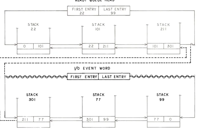
READY QUEUE HEAD
-., I
I I I I I I
r 1 I
I I
I r J
: :
Vo EVENT WORD
I I
I I I
-I [
I
v '""' ,'""' ,'""' ,'""' ,'""' ,'""' ,'""' ,'""' ,'""' ,'""' ,'""' ,'""' ~ FIR 5 TEN TRY I L A 5 TEN TRY ~ ,-,'"',-,'"',-,'"' ,'"' ,'""' ,~ ,~ ,'""',-,'""' ,'""' ,'""' ...: 1
5TACK
301
STACK 77
STACK 99
! I
L
6. SWITCHING FROM EVENT WAIT QUEUE
TO READY QUEUE
The wait intrinsic suspends the process and puts the process to sleep by linking
the process stack into the WAITQUE (queue of processes waiting for event to
happen) of the event. There may be a number of processes waiting on the sameevent.
Later on, when the I/O is completed, the IOFINISH procedure will CAUSE
that event.
The CAUSE intrinsic sets the state of the event to 'happened' and wakes up the
processes by moving all the stacks from the event's WAITQUE to the READYQ.
Figure 6 shows how simple the switching mechanism is. The dotted lines show the
whole set of stacks being linked into READYQ. The scratched out lines show the
removed links of WAITQUE.
Once the occurrence of the event is recognized, and the appropriate action taken,
then the event may be reset so that it may be used to note other I/O happenings.
In fact, it may be desirable for a process using a large number of buffers to use
a single event for all buffers, polling to check I/O completion for an individualbuffer.
ON SOFT'r/ARETIMER EVENT, BEGIN
DISABLE(11);
COMMENT RESEARCH LOOKS FOR FILE; IF RESEARCH THEN DISABLE(12);
ELSE GO TRYAGAIN; INTERRUPT 11:
END;
ON MYREPLYEVENT, DISABLE (11,12); INTERRUPT 12:
COMMENT CODE FOR ACTIVATING SOFTWARE INTERRUPT;
ENABLE (12);
TRYAGAIN:
ENABLE (11);
HOLD;
FILEFOUNO:
Fig. 7. SOFTWARE INTERRUPT DECLARATION
SOFTWARE INTERRUPTS
The software interrupt in ESPOL provides for the interruption of a process when
the interrupt-associated event is CAUSED. The process, if active, will be
immediately interrupted. However if the process is inactive and the software
interrupt is directed at it, then an entry will be made in an Interrupt queue for
that event. When the process is reactivated, it handles all the outstanding
interrupts first before resuming at the point where it was deactivated. The handling
of the software interrupt involves executing, as a procedure the statements
asso-ciated with the interrupt declaration.
The software interrupts in ESPOL are used in those cases where the process waits,
not on a single event, but a combination of two or more events (sometimes known as
"complex sleeps"). Consider a process FINDINPUT which looks for an input file. If
no file is found, the process sends a message to the operator and then sleeps until
either a message is received or the file is located by checking all peripheral
units at a certain interval of time. Figure 7 shows a software interrupt
declar-ation and associated code for such purpose.
ENABLE sets a bit in the Program Control Word associated with the interrupt
declaration so that the code will be executed on interrupt. HOLD puts the process
to sleep unconditionally until it is awakened by either of the interrupts. The
immediate thing to do, on waking up, is to disable the other interrupt to prevent
further interrupts. DISABLE is used for such purpose. It is also shown that a
particular interrupt can be again enabled if the required condition is not satisfied.
Similarly an "AND" condition can be handled by using two consecutive waits on events
associated with software interrupts.
LOCKS
In the B6500, since both processors may operate in control state, it is necessary
to prevent access to other processes when one process is manipulating common tablesor
queues. For such a purpose, global variables are used in conjunction with a
special "Read with Lock (RDLK)" operator.
LOCK and UNLOCK may be used as typed or untyped procedures. If a process encounters
a locked resource, then it may have to suspend itself and wait on some event.
How-ever, for some critical situations, it is desirable that the process should spin or
"BUZZ" until the locked resource is made available. If several processes are buzzing
the same system resource "simultaneously'! only one will go through the lock when it
is released because of the swap (which takes only one memory cycle) characteristic
of the RDLK operator. The other processes will keep on spinning until they can
pass through the lock.
I/O INITIATION AND COMPLETION
So far the basic elements involved in an I/O cycle have been discussed. It is
worthwhile now to go through the whole cycle, in brief, to make the picture
com-plete and clear. Right after initialization, STATUS is fired up and from then on
STATUS takes on the job of process initiator as entries are made to the system.
OPENING A FILE
For each file, the compiler builds up a file parameter block which may be modified
(through information supplied by control cards) by a CONTROLCARD process. When
the file is accessed, the FILEOPEN procedure builds a file information block which
may be also modified by file attribute statements in the program. When the first
record is requested (READ or WRITE), FILEOPEN makes up a label equation block
(LEB) and calls either the FINDINPUT procedure to locate an input file or the
FINDOUTPUT procedure to find an available unit. FINDINPUT will compare the LEB
with each block pointed to by an entry in UNITINFO table built up by STATUS. If
the match is found, then the unit is assigned and its number returned, otherwise
FIND INPUT sends "NO FILE" message to the operator and goes in a complex sleep as
discussed earlier. FINDOUTPUT similarly looks for a free unit of a given type
or stores information on a specified backup storage medium e.g., printer backup
on a magnetic tape or a disk.
1/0 REQUEST
Once the unit is assigned, buffer space is obtained and an IOCB is formed and
passed to procedure IOREQUEST for starting the I/O. IOREQUEST first links the
entry into the specified unit queue and, if that happens to be the only I/O request
for the unit, calls STARTIO. STARTIO interrogates for a path. If a path is
avail-able, then INITIATEIO is called; otherwise, the unit entry is inserted into the
WAITCHANNELQUE for a designated multiplexor. If the unit is common to both
multi-plexors, then the count of the entries (by a "POPULATION" algorithm) in each
multiplexor is made and the entry is made to balance the population of the queues.
In INITIATEIO, the actual hardware operator SCAN OUT is executed. The initiation
of the bookkeeping functions are also done at this time. The breaking up of the
initiation cycle into such logical steps is convenient for later entry at these
points rather than going through the whole cycle again. On return, the process
may wait on the event right away or may continue until that particular buffer is
1/0 COMPLETE
Later
on, a multiplexor interrupt indicates I/O completion. The MCP's hardware
interrupt-handling procedure will call the IOFINISH procedure. IOFINISH identifies
the unit on which I/O completion occurred and reads the result descriptor. It
then picks up IOCB which is at the head of that unit I/O queue. The resultdescriptor
is checked for errors; if found, the IOERROR process is fired up to
handle the I/O errors. If the operation is error free, then the WAITCHANNELQUE ischecked.
If an entry is found, then NEWIO procedure is called to initiate an I/O
on a new unit and if more I/O requests are to be done for the current unit then
its entry is made in the WAITCHANNELQUE. The current unit, subsequently, will get
its turn to grab a channel again. For some units, e.g., a tape unit to take
advantage of the tape motion, a buffered printer to speed up operation etc., it
may be desirable to bypass WAITCHANNELQUE and fire up next I/O waiting on the
current unit's I/O queue. The completion of bookkeeping is done here and the entry
is delinked from the queue. Finally, the event for the I/O is CAUSED, which moves
the waiting process from WAIT QUE to READYQ. Eventually, the process will get its
turn to run and the whole cycle can be repeated.
For
special I/O needs, a facility is provided to mask out I/O errors from the
result descriptor. IOFINISH ignores such errors and the process which requested
the I/O upon waking up will handle the errors by itself.
CONCLUSION
It is demonstrated here how the event and queue-oriented software design has
simplified and made it possible to handle I/O in an organized manner. The detail
discussion of the basic I/O system has illustrated briefly the use of the higher
level language for writing the executive programs and has presented an integral
notion of the overall design philosophy of the B6500 system. The B6500 design
capability is fully utilized by embodying the concept of asynchronous processing
in the software design and thus enabling the Master Control Program or any user
program to work like a giant who can sprout as many hands as possible on demand,
to perform its functions.
ACKNOWLEDGEMENTS
A number of people have contributed to the design and implementation of B6500
system. A special mention should be made of B. A. Creech, B. A. Dent, B. M.
Miyakusu for their encouragement in the writing of this paper and of my colleagues
J. G. Cleary, W. C. Price, D. L. Kunker, S. L. Billard, M. Rainer and R. Burnett,
who have contributed to the work described in this paper.
REFERENCES
1.
HAUCK, E. A. and DENT, B. A. (1968):"Burroughs B6500/B7500 Stack Mechanism", Proceedings, 1968 Spring Joint
Computer Conference, p. 245.
Thompson Book Company, Inc., Washington, D. C.
2.
J. R. (1968):"Auerbach on Computer Technology: Burroughs Dares to Differ", Data
Processing Magazine, July, 1968 issue, p. 40.
CLEARY, J. G. (1969):
"Process Handling on Burroughs B6500", Proceedings of Fourth Australian
Computer Conference, Adelaide, South Australia, August, 1969.
4.
Burroughs B6500/B7500 Information Processing Systems Characteristics ManualBurroughs Corporation, Detroit, Michigan.
DAHM, D. M., GERBSTADT, F. H. and PACELLI, Mo M. (1967):
"A System Organization for Resource Allocation", COnml. Assoc. Compo Mach,
Vol. 10, No. 12, p. 772.