A Smart Image Processing-based System for Parking
Space Vacancy Management
Benjamin Kommey
Department of Computer Engineering KNUST
Kumasi, Ghana
Ernest O. Addo
Department of Computer Engineering KNUST
Kumasi, Ghana
Andrew S. Agbemenu
Department of Computer Engineering KNUST
Kumasi, Ghana
ABSTRACT
Drivers often encounter problems associated with locating empty parking slots in parking areas. This paper presents a smart parking lot management system which operates using image processing. An image processing algorithm is used to detect empty parking areas from aerial images of the parking space. The algorithm processes the image, extracts occupancy infor-mation concerning spots, and their positions thereof. The sys-tem also reports if individual parking spots are occupied or oth-erwise. Occupancy information is made available to newly ar-riving drivers by projecting it unto large displays positioned at vantage points near the vicinity. The smart parking lot manage-ment system reduces the stress and time wastage associated with car parking and makes management of such areas less costly.
General Terms
Parking Space Vacancy Management, Image Processing
Keywords
Edge Detection, Morphological Dilation,WiFi, ROI, FOV
1. INTRODUCTION
In recent times, household vehicles have increased rapidly with population growth and economic development. Meanwhile, spaces required to park these cars in public places has rather been in short supply and are becoming very costly too [14, 6, 12]. This rising im-balance is very evident in major attraction areas that witness the in-flux of large numbers of people visiting in motor vehicles. Finding parking spaces in such places during events is challenging. Vehi-cle owners often undergo the extremely frustrating process of driv-ing through the entire area in an unguaranteed search of available parking spots. Productive working hours are lost, fuel is expended, and carbon emissions from conventional engine vehicles increases. Management of these areas often resort to simply providing more parking spaces in order to check this problem. This effort how-ever, compounds the existing problem as locating vacant spots be-come increasingly difficult when the lot is more than half filled. It is therefore quite clear that proper management of available spaces is the most suitable solution. Contrary to the conventional use of war-dens, smart systems that provide readily available spot vacancy in-formation are needed to effectively satisfy these parking demands.
im-plementation of a smart system which uses image processing meth-ods for vehicular detection coupled with wireless network technol-ogy for monitoring parking areas.
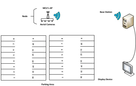
2. PROPOSED SYSTEM MODEL 2.1 Architecture of System
The smart parking system proposed in this paper consists of three main components. These are the parking detection nodes with in-corporated WiFi access points (APs) deployed within each ma-jor section of the parking facility, a wireless local area network (WLAN) integrated local base station, and a notification system for information delivery. The architecture of the proposed system is shown in Figure 1.
1 2 3 4 5 6 7 8 9 11 10 12 13 14 15 16 1 2 3 4 5 6 7 8 9 11 10 12 13 14 15 16 Base Station Display Device Aerial Cameras
MCU s AP
[image:2.595.333.553.92.216.2]Parking Area Node
Fig. 1. Architecture of proposed parking management system.
The parking area is logically demarcated into major sections for easy deployment of parking detection nodes. Each major section of the area is equipped with a detection node. A node consists of wide field view cameras for taking snapshots of the assigned parking mi-nor section at regular intervals and IEEE 802.11 b/g/n compatible microcontroller unit (MCU) for communication between the node and the base station. As shown in Figure 2, a node is affixed at a higher altitude close to the perimeter of its assigned parking section such that the node overlooks the area and the cameras are able to capture their individual regions of interest (ROIs) or minor sections in their field of view (FOV).
Each node’s control unit is built around the TI CC3200 microcon-troller which operates on an industry-standard ARM Cortex-M4 core running at 80 MHz. The cameras are connected to the MCU via the chip’s fast parallel camera peripheral interface. The image sensor interface receives captured images from the camera imme-diately they are taken. The controller forwards the collected data to the base station over the setup local area network. For larger park-ing area, repeaters could be employed to enhance wireless com-munication between the nodes and the central station by regen-erating signals transmitted over the network before they becomes too weak or corrupted. The base station receives the data from the nodes, processes them, retrieves vacancy information from the im-ages, and updates the occupancy status of the parking lot and its vacancy thereof on the display positioned at vantage points.
1 2 3 4 5 6 7 8 9 11 10 12 13 14 15 16 R O
I 3 ROI 4
[image:2.595.60.287.259.403.2]1 2 3 4 5 6 7 8 9 11 10 12 13 14 15 16 R O I 1 R O I 2
Fig. 2. Camera positions with their respective FOVs and assigned ROIs.
2.2 System Operation
The operation of the system involved four major sub-operations as shown in Figure 3
System Initialization Image Acquisition and Processing Data Interpretation Display Update
Fig. 3. Operational modules of proposed system.
[image:2.595.321.553.327.482.2]during subsequent image processing of images. These coordinates could be used as references as long as positions and orientations of the nodes are fixed. Replacement of faulty cameras, change of positions of existing devices or installation of new ones would re-quire re-initialization of the system thereafter. Figures 4, 5, 6, 7, and 8 illustrate the processing of the initial frame. At the base station, the received images undergo a preprocessing stage which involves the reduction of the cost of computing the image informa-tion [1]. The coloured image is grayscaled using the Luminosity method which calculates each resultant gray image pixel,Igrayas
a weighted sum of the three linear-intensity RGB values.Igrayis
related to its respective colour image RGB values:Ired,Igreen, and Iblueby equation 1.
[image:3.595.346.525.216.364.2]Igray= 0.213(Ired) + 0.715(Igreen) + 0.072(Iblue) (1)
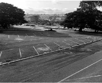
[image:3.595.84.265.251.396.2]Figure 4 shows the image of an empty minor section of a test park-ing area.
Fig. 4. An empty minor section of a test parking space.
The grayscaled image is then linearly normalized by contrast stretching to adjust image intensity values and compensate for poor image contrast which may occur due to glare. The stretched image is smoothed to remove noise and enhance accuracy of object de-tection and then binarized using Otsu’s global thresholding method which chooses the threshold to minimize the intraclass variance of the thresholded black and white pixels. The resulting blurred and binarized image is shown in Figure 5.
Fig. 5. Grayed, linearly normalized, and binarized image of empty minor section.
Canny edge detection is performed to identify the edges of elements in the binarized image. The edge detection process uses the first derivative of the Gaussian to approximately optimize the product of signal-to-noise ratio and localization. The Canny edge detector first smoothens the binarized image with a Gaussian filter with kernel size (σ) of 5 to reduce noise and unwanted details and textures. The gradient is then computed using the Sobel-Feldman gradient oper-ator. Non-maximum suppression is performed on the combined re-sult of the Sobel-Feldman convolutions to thin out edges. Double thresholding using thresholds,T1= 0.6 andT2= 0.85 was done to
[image:3.595.398.471.452.599.2]ensure less noise and fewer false edges. Finally edge tracking by hysteresis was performed to determine which weak edges were ac-tual edges. Figure 6 shows the image obtained from applying the canny edge detection algorithm to the image in Figure 5.
Fig. 6. Strong edges identified in binarized test image using the Canny edge detection algorithm.
A four stage morphological dilation was performed on the resulting image for better and clearer outer borders. Four different flat linear structuring elements were applied in the morphological operations. The shapes and sizes of the structuring elements (SEn) were:
SE1=
1 1 1
SE2=
"1
1 1
#
SE3= "
1 0 0 0 1 0 0 0 1
#
SE4=
"0 0 1
0 1 0 1 0 0
#
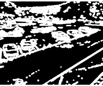
The outputs of the complete dilation procedure are shown in Fig-ure 7. A flood-fill operation is performed on background pixels of the binary image to fill holes in detected objects as shown in Fig-ure 8. Each hole is a set of background pixels that cannot be reached by filling in the background from the edge of the image.
[image:3.595.86.263.521.665.2]Fig. 7. Resulting edge image after fourth dilation
Fig. 8. Dilated edge image with holes filled
measured mean pixel value per identified spot in Figures 9 and 10 for the empty parking space during initialization.
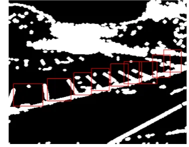
Fig. 9. Identified and marked park spaces in ROI of Figure 7
During subsequent operations of the system, parking areas in the filled binarized images are marked with bounding-boxed regions based on the coordinates obtained from the initialization process. Pixel count in each region is determined and compared against the stored initial values. Parking spots with cars would have extra edges within the marked regions which increases the mean inten-sity within the regions. A substantial increase in a region’s pixel
[image:4.595.82.263.238.394.2]Fig. 10. Identified and marked park spaces in ROI of Figure 8
Fig. 11. A graph showing the mean intensity per empty parking region from Figures 9 and 10
count infers occupancy of the corresponding spot. This occupancy information is then sent from the base station to the display devices for use by incoming drivers.
3. TESTING, RESULTS AND DISCUSSION
[image:4.595.344.526.436.581.2]The proposed parking space vacancy management system was tested to determine its ability to accurately extract vacancy infor-mation from captured images of the parking space. A test image was obtained using an 8MP aerially positioned camera. The im-age used is shown in Figure 12. The imim-age was grayed, stretched, smoothed, and binarized by using the image processing techniques described earlier. Figure 13 shows the grayed, smoothed and bina-rized test image.
Fig. 12. Test image showing parking space minor section with cars in some spots.
[image:4.595.81.265.447.594.2]Fig. 13. Grayed, contrast stretched, and binarized test image
[image:5.595.83.264.242.389.2]Fig. 14. Edge test image obtained using the Canny algorithm.
Fig. 15. Completely dilated test edge image
The parking spots in Figures 15 and 16 were all marked as shown in Figures 17 and 18 and their individual bounded pixel measurements were taken. The graph in Figure 19 shows the pixel counts for each park spots in both images.
Graphical data in Figure 19 shows a substantial increase in the mean pixel count in regions which had cars occupying park spots when compared to the data in Figure 11’s graph. In spot vacancy de-termination, the average percentage increase in intensity recorded for occupied spots when using the filled images (Figures 10 and 18) was 166.9% with a mean absolute deviation (MAD) of 96.4.
[image:5.595.346.526.245.392.2]Fig. 16. Dilated edge test image with holes in detected objects filled
Fig. 17. Marked park spaces in dilated test edge image
Fig. 18. Marked park slots in filled edge image
[image:5.595.84.263.417.566.2] [image:5.595.345.526.423.573.2]Fig. 19. A graph showing the mean intensity per parking region from Fig-ures 17 and 18
right side of the sensor’s FOV. In these instances, the dilated edge image approach exhibited good success.
4. CONCLUSION
The proposed system accurately detected the presence of cars in parking slots. The filled image approach performed better than the use of dilated edge images to determine vacancy of parking spots. The two approaches could be fused into one system. The camera position could be adjusted to improve the performance. From the above set of test results, it has been shown that the proposed image-processing-based system is a viable option for parking space va-cancy management. Other technologies such as automatic number plate recognition and traffic light control could be conjoined with this system to form holistic intelligent transport systems.
5. REFERENCES
[1] A. S. Agbemenu, J. Yankey, and E. O. Addo. An automatic number plate recognition system using opencv and tesseract ocr engine.International Journal of Computer Applications, 180:1–5, 2018.
[2] J. P. Benson, T. O’Donovan, P. O’Sullivan, U. Roedig, and C. Sreenan. Car-park management using wireless sensor net-works. In31st IEEE Conf. Local Computer Networks, pages 588–595, 2006.
[3] M. Caliskan, D. Graupner, and M. Mauve. Decentralized dis-covery of free parking places. InVANET 06: 3rd international workshop on Vehicular ad hoc networks, pages 30–39, 2006. [4] S. C. Hanche, P. Munot, P. Bagal, K. Sonawane, and P. Pooja.
Automated vehicle parking system using rfid. International Journal on Research and Development, 1:89–92, 2013. [5] Y. Hirakata, A. Nakamura, K. Ohno, and M. Itami.
Naviga-tion system using zigbee wireless sensor network for parking. In12th International Conference on ITS Telecommunications, pages 605–609, 2012.
[6] T. Huang, Z. Zeng, and C. Li. Design and implementation of a prototype smart parking (spark) system using wireless sensor networks. InInternational Conference on Neural Information Processing, pages 506–515, 2012.
[7] A. Kianpisheh, N. Mustaffa, P. Limtrairut, and P. Keikhos-rokiani. Smart parking system (sps) architecture using ultra-sonic detector.International Journal of Software Engineering and Its Applications, 6:55–58, 2012.
[8] Z. Pala and N. Inanc. Implementation of rfid technology in parking lot access control system. In12th International Con-ference on ITS Telecommunications, pages 1–3, 2007. [9] R. Panayappan, J. M. Trivedi, A. Studer, and A. Perrig.
Vanet-based approach for parking space availability. InVANET 07: Fourth ACM International Workshop on Vehicular Ad-Hoc Network, pages 75–76, 2007.
[10] S. Srikanth, P. Pramod, K. Dileep, S. Tapas, M. U. Patil, and C. B. N. Sarat. Design and implementation of a prototype smart parking (spark) system using wireless sensor networks. In International Conference on Advanced Information Net-working and Applications Workshops, pages 401–406, 2009. [11] S. Srikurinji, U. Prema, S. Sathya, and P. Manivannan. Smart
parking system architecture using infrared detector. Interna-tional Journal of Advanced Information and Communication Technology, 2:1113–1116, 2016.
[12] D. Teodorovic and P. Lucic. Intelligent parking systems. European Journal of Operational Research, 175:16661681, 2006.
[13] J. Wolff, T. Heuer, H. Gao, M. Weinmann, S. Voit, and U. Hartmann. Parking monitor system based on magnetic eld sensors. In IEEE Conference on Intelligent Transportation Systems, pages 1275–1279, 2006.
[14] G. Yan, S. Olariu, M. C. Weigle, and M. Abuelela. Smart-parking: A secure and intelligent parking system using notice. In11th International IEEE Conference on Intelligent Trans-portation Systems, pages 569–574, 2008.