A Grid Integrated PMSG Using Wind Energy
Conversion System with Various Pitch Angle
Control Technique
Girija Shankar Biswal1, Abhimanyu Mohapatra2
M.Tech scholar, College of Engineering & Technology, Bhubaneswar, Odisha, India1
Asst. Professor, College of Engineering & Technology, Bhubaneswar, Odisha, India2
ABSTRACT: The increasing installed wind power capacity has caused wind power generation to become a significant percentage of the entire electric power generation. As a consequence, the power system operators have included wind power plants regulation to improve the control of the overall power system. Therefore, wind power systems are required to verify the grid connection requirements stated by the power system operators. Overall energy demands are increasing day by day, with renewable energy options such as wind power emerging as attractive alternatives to fossil fuels. This thesis is mainly doing simulation using MATLAB® to reduce fluctuation in output parameters by controlling pitch angle which are found in a Permanent Magnet Synchronous Generator (PMSG) based Wind Energy Conversion System (WECS) .PMSG driven by wind turbine is one of the best alternatives for electric power generation which speaks for the best future energy generation. Various control strategies have been developed for obtaining the best performance of a PMSG. We have to control the pitch angle which is the angle of attack of the blades with respect to the wind. This provides a degree of control over the captured power to improve conversion efficiency or to protect the turbine. Fuzzy Logic (FL) controller is used to control the pitch angle of blade. FL controller has less settling time as compare to PI, PID controller. Also controlling action of FL controller is quicker as compare to PI and PID controller. ANN controller is also described to control pitch. Here PMSG fed with WECS integrated with Grid with various power electronic converters to avail uninterrupted power across load which is connected between generator and grid.
KEYWORDS: Pitch controller, renewable energy, variable speed, wind turbine generator, wind energy conversion system, Fuzzy-PID controller, Power electronic converter, Grid integration.
I.INTRODUCTION
power point. The grid side converter is utilized to control created power fed to load and the harmonics and reactive power magnitude of the nonlinear load, so that only smooth sinusoidal current at UPF(unity power factor) supply to the grid. The execution of PMSG based variable rate WECS was dissected under differing wind conditions. A controller was given the generator, grid parameters and turbine pitch angle control. “PI controller” or “FL controller” is utilized to control the wind speed as its variable nature [3]. The grid side inverter is also used to control the dc link voltage in order that the power equilibrium can be preserved under both variable wind speed and grid unsettling influences. Among pitch angle control methods here PI, PID, FUZZY and ANN controller are used [4]. Fuzzy and PI control are the two widely used techniques. Because the blade pitch angle control in WT (wind turbine), which is a significant parameter to control the mechanical power provides a constant torque to provide WT stability. ANN controller also performs good as to control of pitch angle to provide almost constant output [14].
For low power requirement we use DFIG and for small power application PMSG is used. The paper represents a PMSG fed with WECS. WECS can be used in two different ways namely isolated standalone system and Grid connected system. Standalone systems are employed to the needs of small scale industries for rulers areas, such system are located at off places or remote areas. Grid connected system increased energy efficiency, robustness, voltage sustain, enhancement of energy sources, decreased transmission and dispersion losses and reliability of the system [7][8]. Harmonics is the major drawback of this wind energy conversion system as the wind speed is always varying in nature. So researches are been carried out and different harmonic distortion techniques are been developed. Main reason of harmonics in wind energy system is converter system. Some lower categorize harmonics like fifth, seventh, fifth, seventh, eleventh and thirteenth and also some higher order harmonics are available in this structure [9]. It is been suggested to use filters to remove these harmonics. Passive filters are known as band pass filters which can block lower order harmonics and active filters are used to block higher order harmonics [9]. Another criteria is the optimal power harnessing. Optimal power control strategy of maximizing wind energy tracking for Variable Speed Wind Energy Conversion System (VS-WECS) based Permanent Magnet Synchronous Generator (PMSG) and interconnected to the electric network is studied in this paper [10].
The proposed strategy is based on a Control approach for control of both PMSG and grid- side inverter of WECS. The PMSG side rectifier control is used to keep the generator rotor velocity at an optimal value to maximize the generated power from Wind Turbine Generator (WTG) under low, medium or high wind velocity mode. The control methodology is applied for inverter and for generator converter. The efficiency of the proposed VC scheme is confirmed by simulations with different examined cases of wind speed and state of the power grid. The simulation results show that the proposed strategy has excellent performance for normal working conditions as well as for low voltage drop conditions [11]. In this system there is a wind turbine, the output of the wind turbine goes to permanent magnet synchronous generator. The output of the wind system is in ac so we need ac to dc converter to convert the ac output in to dc .Then the output of wind generating system is connected with a common DC link voltage .The common DC link voltage will be connected with the DC to AC converter and the output of the inverter is synchronize with grid. This inverter changes DC power from the wind turbine into AC power and it maintain the voltage and frequency is equal to the grid voltage and frequency [13].
II.PERFORMANCE ANALYSIS
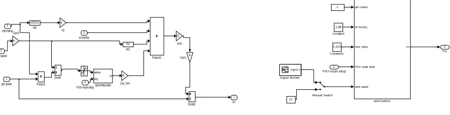
To extract maximum power from wind with a constant manner and constant rotor speed, it is economical to control the pitch angle to make the output constant by different types of controllers. The shape of the blades of rotor is curve because of this structure they deflect the wind. The lift force, created by difference in the velocity of airstream is the main cause of rotor to rotate. In order to produce maximum amount of lift force the blades must lie with an appropriate angle to wind. Tips of the turbine blades are travel faster than points nearer to its axis, the angle of wind seen by the blade changes with the radius. The rotor will become more efficient if the angle seen by the blade will be larger. As more lift force produces more amount of power also extracted from wind. In other hand the pitch utility provides complete control above the mechanical-power. Power control implies as far as possible the offer of the accessible force of wind, when wind speed achieves a preset quality, which is the evaluated esteem. Rated value will be in between 12m/s to16m/s. At the point when wind speed goes underneath the evaluated esteem then the pitch-angle diminishes from the greatest quality to help the turbine quicken quicker. At the point when the wind speed goes above evaluated wind speed, it is about 25m/s called as cut out speed, and then the pitch angle is to keep the generator power at appraised power by diminishing the angle of blades. Additionally pitch angle control is valuable to ensure the turbine at above evaluated speed. Here the below fig-1shows the simulink model of wind turbine system and fig-2 shows various input to wind turbine system.
Fig 1: Simulink model of wind turbine system Fig 2: WTS with various input
The total power available in the wind, where A is the rotor area, ρ isthe air density and v is the wind velocity.
PWIND = 0.5Aρv3
Only a part of the total wind energy can be extracted. The available energy part in wind is described by the power coefficient Cp. The theoretical maximum value of this coefficient is 0.59 and it is called the Betz limit.
PTURBINE = 0.5ρCP Av3
The practical values of Cp lie between 0.4 and 0.5 for industrial wind turbines. This power coefficient is a function of the tip-speed ratio. The tip-speed ratio shows the relation between the circumferential velocity of the blade tips and the wind velocity:
= Ὠ
1 tm pi
rs1
lambda
beta cp
cp(lambda,beta)
Product2
Product1 u(1)*u(1)
Idr2
f(u)
Idr1
-K-Gain2
-K-Gain1 1/2
Gain
Divide1
Divide
-K-1/cp_nom 5
wind speed
4 Pitch angle (deg) 3
rotor radius 2
air density
1 gen speed
1 Tm gen speed
air density
rotor radius
Pitch angle (deg)
wind speed
tm
wind turbin e Signal 1
Si gna l Bui l der
Manual Switch 1
12
1 .52 5
Constant1 1.08
Co nstan t
Where r is the rotor radius and Ω is the angular rotor speed.The performance of wind turbine is characterized by the non dimensional curve of coefficient of performance and λ, as a function of tip-speed ratio . as a function of λ and pitch angle β is expressed by equation (2.5) .
(λ.β) =
λ − β− C e
λ + C λ
With
1
= 1
+ 0.08 − 0.035
+ 1
Where C1 = 0.5176, C2 =116 ,C3 =0.4 ,C4 =5 ,C5 =21 ,C6 = 0.0068
In general, =
III.OPERATING PRINCIPLE AND SYSTEM CONFIGURATION
The blade pitch angle control in case of a wind turbine is also required as that controls the torque and always maintains constant torque. The constant torque is imperative to accomplish a consistent output torque for achieving steadiness of wind turbine. We use various controlling techniques to control the pitch angle of blade. In my project I used four controllers to maintain the blade angle along the wind direction so that we can get constant torque. In the all case of controllers I used error signal as difference between reference and actual torque. The control schemes are
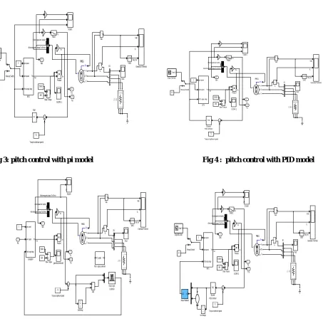
(i)PI controller (ii)PID Controller
Fig 3: pitch control with pi model Fig 4 : pitch control with PID model
Fig 5: Pitch control with FLC Fig 6: Pitch control by ANN controller
Fig-3, 4, 5, 6 shows the pitch angle control of wind energy conversion system with various pitch angle control techniques such as PI,PID,FLC,ANN. The conventional PI,PID model are studied in this thesis where by the controller action are taken from the concerned controller where proportional gain(Kp), integral gain(Ki) and derivational gain(Kd) are predefined. But in fuzzy model membership functions are defined for each of the inputs and these are feed to fuzzy interference system and after defuzzification output will sent to controller and pitch angle will be adjusted accordingly. In ANN controller a learning process will be fed to each inputs with some weights to artificial learned to inputs and output will also achieve by differentiating the errors and these change in errors will be
IL Vab
SCOPE 2
Torqe at optimum speed 3 Wm 2 Tm 1 Te gen speed wind speed
Pitch angle (deg) Tm WTS Vout InRMS Vab3 v + -Vab Signal 1 Signal Builder Scope1 Product Tm m A B C PMSG Manual Switch
A B C A B C
LOAD i + -IL Generator Terminal Filter3 PI Dis2 7.3 12 1 160 15000 Base Torque VabcA B C a b c B1
-K-<Rot or speed wm (rad/s)>
Vab_rms Te
Tm <Electromagnetic torque Te (N*m)>
Tsh
Tm
IL Vab
Torqe at optimum speed 3 Wm 2 Tm 1 Te genertaor terminal2 Vout InRMS Vab3 v + -Vab z 1 Unit Delay gen speed wind speed
Pitch angle (deg) Tm Subsystem Scope1 Product Tm Pitch_angle1 Pitch_angle-controller Tm m A B C PMSG
A B C A B C
LOAD i + -IL Generator Terminal Fuzzy Logic Controller 1 160 7.3 15000 Base Torque VabcA B C a b c B1 Add -K-1 Ws
<Rotor speed wm (rad/s)>
Vab_rms
Tm <Electromagnetic torque Te (N*m)>
<Electromagnetic torque Te (N*m)>
Tsh Tm
IL Vab
SCOPE 2
Torqe at optimum speed 3 Wm 2 Tm 1 Te gen speed wind speed
Pitch angle (deg) Tm WTS Vout InRMS Vab3 v + -Vab z 1 Unit Delay1 Signal 1 Signal Builder Scope1 Product Tm m A B C PMSG x{1} y{1} Neural Network Manual Switch
A B C A B C
LOAD i + -IL Generator Terminal Filter3 PID Discrete PID Controller 7.3 12 1 160 15000 Base Torque Vabc A B C a b c B1 Add2
-K-<Rotor speed wm (rad/s)>
Vab_rms Te
Tm <Electromagnetic torque Te (N*m)>
Tsh Tm
IL Vab
SCOPE 2
Torqe at optimu m speed 3 Wm 2 Tm 1 Te gen speed
wind speed
Pitch angle (deg) Tm WTS Vout InRMS Vab 3 v + -Vab Signal 1
Signa l Builder
Scope 1 Product Tm m A B C PMSG
Ma nual Switch
A B C A B C
LOAD
i
+
-IL
Gene rator Termina l Filter3 PID Discre te PID Controller 7.3 12 1 160 15000
Base Torqu e
VabcA B C a b c B1 -K-<Rotor speed wm (r ad/s)>
Vab_rms Te
Tm <Electromagnetic tor que Te (N*m)>
Tsh
fed to controllers to control pitch angle.Fig-8 shows fuzzy interference system of fuzzy logic controller.Fig-9 shows various input and output with weights of artificial neural network.
Fig 7: Membership function of input e (i), input ce (ii), output dβ (iii) in FLC.
Fig 10: Simulink model of test system
Fig-10 shows the purposed test model shows an grid integrated PMSG supplies power to a load circuit and the uninterrupted supply will be available at load end even if there is any fault at grid as well as generator end. The available power is almost constant in its characteristics which shows successful operation of the test model which is simulated in MATLAB.
IV.SIMULATION AND RESULTS
The purposed simulation of test model are shown above and the results of simulated model is described as below and we can see the output voltage of PMSG with and without pitch angle controller in Fig-11.
Fig 11: output voltage of PMSG without(i) and with(ii) pitch angle controller
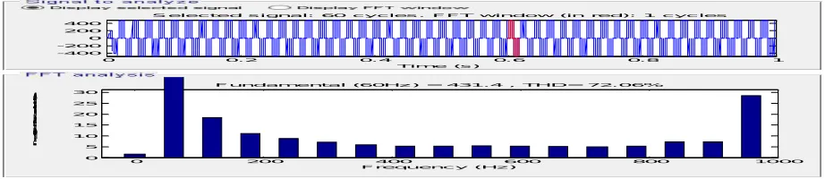
Fig 12: FFT Analysis of output voltage of inverter before filter
Ws Te
Wm
+
-wi nd generati on
-K-vol t->pu
D iscrete, Ts = 2e-005 s.
powergui v + -Vdc v + -V ab_load v + -V ab_inv A B C A B C Thre e-Phase Fa ult1
A B C A B C Three -Pha se Fault Va bcA
B C a b c Three-Phase V-I Mea surement2
Va bc A B C a b c Three-Phase V-I Mea surement1
V a b c Ia b c
A B C
a b c
Three-Phase V-I Measure ment T
Vabc (pu) pulses
Subsystem 2
Signal 1
S ignal Buil der
Scope7
S cope3
S cope2 S cope1
Scope g A B C + -P WM IGB T Inverter1
PULSE
Manual Swi tch
A B C
LOA D A B C A B C
LC Fil ter
S2 Goto6 S1 Goto5 V_grid Goto2 V_wi nd Goto1 V_gri d From5 Vabc_B1 S2 From3 S 1 From 2 V _wind From1 Display1 Display Vabc Iabc P_Q Discrete 3-phase A cti ve & Reacti ve Power Vwind Vgrid S1 S2 Control ler1 12 com A B C a b c C B-2 com A B C a b c C B-1 A B C a b c B1 A B C 480V GRID
0 1000 2000 3000 4000 5000 6000 7000 8000 9000 10000 -200 -150 -100 -50 0 50 100 150 200 Time(ms) V p m s g 3 p h a s e (v o lt s )
Phase A Phase B Phase C
0 1000 2000 3000 4000 5000 6000 7000 8000 9000 10000
-300 -200 -100 0 100 200 300 Time(ms) V p m s g 3 p h a s e (v o lts ) Phase A Phase B Phase C
0 0. 2 0. 4 0. 6 0. 8 1
-400 -200 0 200 400
S elec t ed s i gnal: 60 c y c les . FFT window (in red): 1 c y c les
Time (s )
0 200 400 600 800 1000
0 5 10 15 20 25 30
Frequenc y (Hz )
Fundament al (60Hz ) = 431. 4 , THD= 72. 06%
Fig 13: FFT analysis of output voltage of inverter after filter
A test system is designed to observe various cases which are explained in previous chapter. In fig-14,15,16 a balance three phase fault is occur at 0.4 to 0.5 sec at WECS end and another three phase fault is occurs for 0.7 to 0.8 sec at grid end .But due to control logic developed as explained previously the output voltage at the load terminal maintain nearly a constant level .that means during fault at wind energy generating system the grid supply the power to the load and during fault at grid the WECS supply power to the load to maintain a uninterrupted voltage at the load end .the output of the test model is shown below
Fig 14: output voltage at WECS during fault
Fig 15: output voltage at Grid during fault
Fig 16: ouput voltage across load during fault
0 0.1 0.2 0.3 0.4 0.5 0.6 0.7 0.8 0.9 1
-400 -200 0 200 400
Selec ted s ignal: 60 c y c les . FFT window (in red): 1 c y c les
Ti me (s )
0 100 200 300 400 500 600 700 800 900 1000
0 0.01 0.02 0.03 0.04 0.05
Frequenc y (Hz )
Fundamental (60Hz ) = 478 , THD= 0.10%
M
ag
(
%
o
f F
u
n
da
m
en
ta
l)
0 0.1 0. 2 0. 3 0. 4 0. 5 0. 6 0. 7 0. 8 0. 9 1
-800 -600 -400 -200 0 200 400 600 800
T ime (se c)
V
in
v
e
rt
e
r(
v
olt
s
)
INV ERTE R VOLT. AFTER FILTER
Phas e A Phas e B Phas e C
0 0.1 0. 2 0. 3 0. 4 0.5 0. 6 0.7 0. 8 0. 9 1
-800 -600 -400 -200 0 200 400 600 800
Time(sec)
V
g
ri
d
(v
o
lt
s)
GRID VOLT.
Phas e A Phas e B Phas e C
0 0. 1 0.2 0. 3 0. 4 0. 5 0.6 0. 7 0. 8 0. 9 1
-800 -600 -400 -200 0 200 400 600 800
T ime(sec)
V
lo
a
d
(v
o
lts
)
P -Q c urve
V.CONCLUSION
According to model which is simulated in MATLAB/SIMULINK , it is observed that output of the purposed system is almost constant in nature and this model is being performed well as connected with the grid. As fault occurrence either in generator side or at grid side but uninterrupted supply will available across load.
REFERENCES
[1] A. Remli, D. Aouzellag and K. Ghedamsi, “Full Electrical Strategy Control of Wind Energy Conversion System Based PMSG” In Journal of Electrical Engineering, Vol.-3,issue vi,june2015.
[2] Sourav Ghosh, Pradip Kumar Saha and Gautam Kumar Panda, “Wind Energy Conversion System Connected With Grid Using Permanent Magnet Synchronous Generator (PMSG)” In International Journal of Advanced Research in Electrical,Electronics and Instrumentation Engineering, Vol. 4, Issue 1,pp 120-127, January 2015.
[3] C.Paramasivam, M.Basuki, R.Nandhini and A.Divyalaxmi, “Pitch Controlled PMSG Based Wind Energy Conversion System With Control Of DC link Voltage and Load Voltage Variation,”. In Internatioal Journal for Research in Applied Science and Engineering Technology, Vol.-3,issue vi, pp 459-465, june2015.
[4] Y. Bhanu Chandra M.E. and J.S.L.Tejaswi, “The Pitch Angle Control of Variable Speed Wind Turbine Using PID Controller”,InInternational Journal of Scientific Research and Management,Vol-3,issue-11,pages-3728-3733,2015.
[5] T.Anil Kumar and Ch.V.V.Mangalakshmi, “Pitch Control of DFIGWind Turbine Based on Fuzzy Logic Controller” ,International jounal for science engg and advance technology,Vol-2,Issue-12,pp 1044-1050,2014.
[6] Omer Abbaker Ahmed and Ahmed Awadahmed, “Control of Wind Turbine for Variable Speed Based On Fuzzy-PID Controller,” In Proc.Journal of Engineering and Comp. Science,Vol-8,No.-1,2017.
[7] Ali H. Kasem Alaboudy, Ahmed A. Daoud and Sobhy S. Desouky ,Ahmed A. Salem, “Converter controls and flicker study of PMSG-based grid connected wind turbines”,In Ain Shams Engineering Journal, Vol-4,pp 75-91,2003.
[8] Y. Erramia, M. Ouassaid and M. Maaroufi, “Control of a PMSG based wind energy generation system for power maximization and grid fault conditions”, In Energy Procedia , pp 220 – 229,2013.
[9] K. H. Ahmed, S. J. Finney and B. W. Williams, “Passive filter design for three-phase inverter interfacing in distributed generation,” In Compatibility in Power Electronics, 2007. pp1–9, IEEE, 2007.
[10] Abdel ghani aissaoui, Ahmed tahour, Mohammed Abid and Frederic Nollet, “Power Control of Wind Turbine based on Fuzzy Controllers”, In International Conference on Future Energy, Environment, and Materials, pp 163-172, 2013.
[11] Furat Abdal, Rassul Abbas and Mohammed Abdulla Abdulsada, “Simulation of Wind-Turbine Speed Control by MATLAB”, In International Journal of Computer and Electrical Engineering, Vol. 2, No. 5, pp 910-915, October, 2010.
[12] Anjali Jain and Aarati bhandarkar, “ wind turbine speed control using MATLAB”. In International Journal of Scientific and Research Publication,Vol.-4,Issue-5,2014.
[13] Yuan-Kang Wua and Wu-Han Yang, “Different control strategies on the rotor side converter in DFIGbased wind turbines” ,In Energy procedia,pp551-555,2016.
[14] Ahmet Serdar Yilmaz and Zafer Ozer, “Pitch angle control in wind turbines above the rated wind speed by multi-layer perceptron and radial basis function neural networks”, In Expert Systems with Applications, Vol-36, pp 9767–9775,2009.
[15] Ankush Mudholker, P. M. Menghal and A. Jaya Laxmi, “SVPWM Based Converter for PMSG Based Wind Energy Conversion System”, In International Journal of Engineering Science and Advanced Technology, Vol-20, pp676-682, 2015.
[16] Sasi.C and G.Mohan, “Performance Analysis of Grid connected Wind Energy Conversion System with a DFIG during Fault Condition” ,In International Journal of Computer Applications ,Vol-70, No.19, May 2013.