© 2019, IRJET | Impact Factor value: 7.211 | ISO 9001:2008 Certified Journal
| Page 576
EFFECT OF WASTE PLASTIC OIL AS AN IC ENGINE FUEL IN
COMBINATION WITH DIESEL IN CI ENGINE:
AN EXPERIMENTAL INVESTIGATION
Prenav T Nair
1, Jumin S Thomas
2, Krishnarag S
3, Karthik Das P
4,Vipin R
51
Student, Dept. of Mechanical Engineering, Musaliar College of Engineering and Technology, Pathanamthitta,
Kerala, India
2
Student, Dept. of Mechanical Engineering, Musaliar College of Engineering and Technology, Pathanamthitta,
Kerala, India
3
Student, Dept. of Mechanical Engineering, Musaliar College of Engineering and Technology, Pathanamthitta,
Kerala, India
4
Student, Dept. of Mechanical Engineering, Musaliar College of Engineering and Technology, Pathanamthitta,
Kerala, India
5
Assistant Professor, Dept. of Mechanical Engineering, Musaliar College of Engineering and Technology,
Pathanamthitta, Kerala, India
---***---Abstract -
Due to increase in industrialization andurbanization, there is rapid decrease in the conventional fuels. The price of conventional fuels is going on increasing day to day and also increasing environmental pollution due to more usage. If this goes on there will be no longer the conventional fuels. There is a need to search for alternative fuels for the automobile applications. Environmental degradations and depletion of oil reserves are matters of great concern around the globe. So, in this project we are trying to establish a new blend by analysing its performance and emission characteristics. And the blend we are selected is Waste Plastic Oil with Diesel. The various performance characteristics such as BSFC VS LOAD, BTE VS LOAD, VE VS LOAD, and emission characteristics such as OPACIY VS LOAD will be analysed. The test will be conducted on a 4-stroke single cylinder variable compression ratio diesel engine. And the compression ratios for the experiment will be 16 and 18.
Key Words: Waste plastic oil, Variable compression ratio engine, Engine performance, Emission characteristics
1.INTRODUCTION
All petro-chemical fuels are extracted from the earth crust, in that diesel is the main constituent source for the transportation sector. As the population is getting escalated the usage of diesel engines for various purposes is getting enormous. Developing countries like India depends heavily on crude oil import of aroud125 Mt per annum. Diesel being
the main transportation in India finding a suitable fuel alternate to diesel is an urgent need. The prices of the traditional fuels are growing day by day as such the costumers cannot afford any more. Quick exhaustion of fossil fuels has created a challenge for the researchers to find an appropriate alternative for traditional fuels like diesel and petrol.
In the past few decades, fossil fuels mainly petroleum, natural gas, coal have been playing an important role as the major energy sources worldwide. However, these energy sources are non-renewable and are projected to be exhausted in near future. Internal Combustion engines operate mainly on petroleum base fuels. Diesel engines (C.I) are one among the leading machines in modern automobile industry because of its excellent drivability and thermal efficiencies. In the context of fossil fuel crisis and increasing vehicle population the search for Alternative fuel has become necessary for diesel engines due to increased environmental concerns, and socio economic aspects. The other reasons are high cost of petroleum products, emission problems and large percentage of crude oil is imported from other countries which control the larger oil fields. Due to these reasons scientists work on alternate fuel sources, so vegetable fuel studies become current among various investigations.
2. LITERATURE REVIEW
© 2019, IRJET | Impact Factor value: 7.211 | ISO 9001:2008 Certified Journal
| Page 577
emitting harmful gasses from exhaust which in turn leads toenvironmental pollution, the pollution that has been exhausted from automobile creating serious health issues for mankind, soil and crops are getting damaged due to these effects, efforts were made in this experimentation part to find an alternative source for diesel fuel and also to diminish the emission effects.
A.V. Krishna Chaitanya [1] investigated performance and emission characteristics of VCR diesel engine in which diethyl ether was added with diesel, results consolidate that smoother running of engine and slight increase in brake thermal efficiency and decrease in specific fuel consumption is observed in the case of esterified mahua oil compared to that of diesel
EC Prasad Nidumolu [2] investigated performance and emission analysis of Palm oil methyl ester (PME) blended with diesel in a single cylinder direct injection diesel engine. Results shown that thermal efficiencies of all blends of PME is closer to diesel efficiency with lower emissions of CO and HC.
Bridjesh [3] experimental results showed reduction in brake thermal efficiency, nitric oxide and increase in brake specific fuel consumption, carbon monoxide, hydro carbon with Calophyllum inophyllum biodiesel blends than neat diesel.
.Lopez [4] investigated the effect of the use of olive–pomace oil biodiesel/diesel fuel blends in a compression ignition engine. olive–pomace oil methyl ester blended with diesel fuel, was evaluated as fuel in a direct injection diesel engine Perkins AD 3-152 and compared to the use of fossil diesel fuel. It was found that the tested fuels offer similar performance parameters. When straight biodiesel was used instead of diesel fuel, maximum engine power decreased to 5.6%, while fuel consumption increased up to 7%.
Nilamkumar. S. Patel [5] has done experiments on diesel engine by using waste plastic oil as fuel, and the tests are conducted at different blends and the results concludes that waste plastic oil blends with diesel can be directly used in the engine without any modification, to reduce the viscosity of waste plastic oil ethanol is added and introduced into the diesel engine for better results
K. Sandeep Kumar [6] investigated the performance and emission analysis of Mahua oil methyl ester (MOME) blended with diesel along with additive of diethyl ether in a single cylinder direct injection diesel engine. Results shown that there is rise in Brake Specific Fuel Consumption (BSFC) with rise in percentage of MOME in biodiesel blend when compared to diesel, but Break thermal efficiency (BTE) is slightly increases with increase in percentage of MOME in biodiesel blend. The emissions of CO, NOX and HC were reduced with increase in percentage of MOME in biodiesel blend, but CO2 emissions were increased.
M.M Rahman and S.Stevanovic [7], investigated the influence of different alternative fuels on particle emission from a turbocharged common diesel engine and concluded that, at full load with bio diesel the particle mass can be reduced to 3%Particle mass emission for biodiesel is lower than neat diesel
K Srithar, K Arun Balasubramanian, V. Pavendan [8], investigated the effect of mixing of two biodiesels (MUSTARD OIL & PANNATA OIL) blended with diesel as alternative fuel for diesel engines, and they concluded that the thermal efficiency and Mechanical efficiency of blends were slightly higher than the diesel. Specific fuel consumption values of dual biodiesel blends were comparable to diesel. Dual biodiesel blends having slightly less CO & CO2 emissions.
3.THEORY
3.1
PYROLYSIS
Pyrolysis is the thermaldecomposition of materials at elevated temperatures in an inert atmosphere. It involves a change of chemical composition and is irreversible. Pyrolysis is most commonly used in the treatment of organic materials. It is one of the processes involved in charring wood. In general, pyrolysis of organic substances produces volatile products and leaves a solid residue enriched in carbon, char. Extreme pyrolysis, which leaves mostly carbon as the residue, is called carbonization. The process is used heavily in the chemical industry, for example, to produce ethylene, many forms of carbon, and other chemicals from petroleum, coal, and even wood, to produce coke from coal. Aspirational applications of pyrolysis would convert biomass into syngas and bio char, waste plastics back into usable oil, or waste into safely disposable substances. Pyrolysis generally consists in heating the material above its decomposition temperature, breaking chemical bonds in its molecules. The fragments usually become smaller molecules, but may combine to produce residues with larger molecular mass, even amorphous covalent solids. In many settings, some amounts of oxygen, water, or other substances may be present, so that combustion, hydrolysis, or other chemical processes may occur besides pyrolysis proper. Sometimes those chemicals are added intentionally, as in the burning of firewood, in the traditional manufacture of charcoal, and in the steam cracking of crude oil. Conversely, the starting material may be heated in a vacuum or in an inert atmosphere avoid adverse chemical reactions. Pyrolysis in a vacuum also lowers the boiling point of the by-products, improving their recovery.
© 2019, IRJET | Impact Factor value: 7.211 | ISO 9001:2008 Certified Journal
| Page 578
(coke), and as structural materials. High temperaturepyrolysis is used on an industrial scale to convert coal into coke for metallurgy, especially steelmaking.
3.2
PYROLISIS REACTOR
In our experiments, commercialize available shredded plastics were procured and washed before pyrolysis. One of the most favorable and effective disposing method is pyrolysis, which is environment friendly and efficient way. Pyrolysis is the thermal degradation of solid wastes at high temperatures (300-9000C) in the absence of air and oxygen.
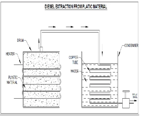
As the structure of products and their yields can be considerably modified by catalysts, results of pyrolysis in the absence of catalyst were presented in this article Pyrolysis of waste plastics was carried out in an indigenously designed and fabricated reactor. Fig shows the scheme of the process involved in the experiments and the photograph of the experimental set up respectively. Waste plastics had been procured form the commercial source and stored in a raw material storage unit. Raw material was then fed in the reactor and heated by means of electrical energy. The yield commenced at a temperature of 3500C. The gaseous products
resulting from the pyrolysis of the plastic wastes is supplied through the copper tube. Then the burned plastic gas condensed in a water-cooled condenser to liquid fuel and collected for experiments.
Fig -1: 2D Drawing of Layout of Pyrolysis Reactor
3.3
DENSITY
The density, or more precisely, the volumetric mass density, of a substance is its mass per unit volume. The symbol most often used for density is ρ (the lower case Greek letter rho), although the Latin Letter D can also be used. Mathematically, density is defined as mass divided by volume:
ρ = m / v
where ρ is the density, m is the mass, and V is the volume. In some cases (for instance, in the United States oil and gas industry), density is loosely defined as its weight per unit
volume although this is scientifically inaccurate – this quantity is more specifically called specific weight.
For a pure substance the density has the same numerical value as its mass concentration. Different materials usually have different densities, and density may be relevant to buoyancy, purity and packaging. Osmium and Iridium are the densest known elements at standard conditions for temperature and pressure but certain chemical compounds may be denser.
To simplify comparisons of density across different systems of units, it is sometimes replaced by the dimensionless quantity "relative density" or "specific gravity", that is the ratio of the density of the material to that of a standard material, usually water. Thus, a relative density less than one means that the substance floats in water.
Density is an important property of a fuel oil. If the density of fuel is high; the fuel consumption will be less. On the other hand, the oil with low density will consume more fuel which may cause damage to the engine. Therefore, too low or too high density of fuel oil is not desirable.
3.4
CALORIFIC VALUE
The calorific value or heat of combustion of a fuel oil is a measure of the amount of heat released during complete combustion of a unit mass of the fuel, expressed in kilojoules per kilogram. Calorific value is usually determined by a calorimeter and using the following equation:
Gross Calorific Value, CVgross = [ mW.CW.(Two – Twi)]
mF
where mF and mW are the mass flow rate of fuel and water
respectively, Two and Twi are the outlet and inlet
temperature of water respectively and CW is the specific heat
of water.
If water is condensed and collected from the gas outlet for a specified time interval,
then the net calorific value is,
CVnet = CVgross – WChC
where, WC = mass of water condensed and hC = heat of
condensation of water vapor.
3.5
VISCOSITY
The viscosity of a fluid is a measure of its resistance to deformation at a given rate. For liquids, it corresponds to the informal concept of "thickness": for example, syrup has a higher viscosity than water
[image:3.595.55.289.413.606.2]© 2019, IRJET | Impact Factor value: 7.211 | ISO 9001:2008 Certified Journal
| Page 579
motion: the strength of this force is proportional to theviscosity.
A fluid that has no resistance to shear stress is known as an ideal or inviscid fluid. Zero viscosity is observed only at very low temperatures in super fluids. Otherwise, the second law of thermodynamics requires all fluids to have positive viscosity; such fluids are technically said to be viscous or viscid. A fluid with a relatively high viscosity, such as pitch, may appear to be a solid. In many fluids, the flow velocity is observed to vary linearly from zero at the bottom to ‘v’ at the top. Moreover, the magnitude F of the force acting on the top plate is found to be proportional to the speed ,v and the area of each plate A, and inversely proportional to their separation y :
F = µ.A.v/y
The proportionality factor µ is the viscosity of the fluid, with units of Pa.s (Pascal-Seconds). The ratio v/y is called the rate ofshear deformation or shear velocity, and is the derivative of the fluid speed in the direction perpendicular to the plates. Viscosity varies with feedstock, pyrolysis conditions, temperature, and other variables. The higher the viscosity, the higher the fuel consumption, engine temperature, and load on the engine. On the other hand, if the viscosity of oil is too high, excessive friction may take place. The viscosity was measured by the IP-50 methodology at a temperature of 40˚C. From Figure 4 it is observed that the viscosity of waste plastic pyrolysis oil obtained at 425 ˚C pyrolysis temperature was 1.98 cSt which was comparably higher than kerosene and lower than diesel.
One of the important properties of a fuel on which its efficiency is judged is its calorific value. The calorific value is defined as the energy given out when unit mass of fuel is burned completely in sufficient air. The calorific value of WPO was estimated according to IP 12/58method.
3.6
FLASH AND FIRE POINT
The flash point of a volatile material is the lowest temperature at which vapors of the material will ignite, when given an ignition source.
The flash point is sometimes confused with the auto ignition temperature, the temperature that results in spontaneous auto ignition. The fire point is the lowest temperature at which vapours of the material will keep burning after the ignition source is removed. The fire point is higher than the flash point, because at the flash point more vapor may not be produced rapidly enough to sustain combustion. Neither flash point nor fire point depends directly on the ignition source temperature, but ignition source temperature is far higher than either the flash or fire point. The fire point of a fuel is the lowest temperature at which the vapour of that fuel will continue to burn for at least 5 seconds after ignition by an open flame. At the flash point, a lower temperature, a substance will ignite briefly, but vapor might not be produced at a rate to sustain the fire. Most
tables of material properties will only list material flash points. Although in general the fire points can be assumed to be about
10 °C higher than the flash points this is no substitute for testing if the fire point is safety critical. Testing of the fire point is done by open cup apparatus.
Flash point is used to characterize the fire hazards of fuels. The flash point of WPO was measured according to ASTM D 93-62 method. The fire point of WPO was measured by using ASTM D 97-57 methodology.
3.7
CARBON RESIDUE
It provides an indication of the coke -forming tendencies of an oil. Quantitatively, the test measures the amount of carbonaceous residue remaining after the oil's evaporation and pyrolysis. In general, the test is applicable to petroleum products which are relatively non-volatile, and which decompose on distillation at atmospheric pressure. numerical value obtained from it. The carbon residue of WPO was measured according to ASTM D 189-65 method.
3.8
BRAKE THERMAL EFFICIENCY
It is the ratio of the heat equivalent to one kW hour to the heat in the fuel per B.P. hour. Mathematically, brake thermal efficiency:
ȠBTE = Heat equivalent to one Kilowatt hour
3.9
VOLUMETRIC EFFICIENCY
It is the ratio of the actual volume of charge admitted during the suction stroke at N.T.P to the swept volume of the piston.
3.10
BRAKE SPECIFIC FUEL CONSUMPTION
Brake-specific fuel consumption (BSFC) is a measure of the fuel efficiency of any prime mover that burns fuel and produces rotational, or shaft power. It is typically used for comparing the efficiency of internal combustion engines with a shaft output.It is the rate of fuel consumption divided by the power produced. It may also be thought of as power-specific fuel consumption, for this reason. BSFC allows the fuel efficiency of different engines to be directly compared.
3.11
BRAKE POWER
The brake power (briefly written as B.P.) of an IC Engine is the power available at the crankshaft. The brake power of an I.C. engine is, usually, measured by means of a brake mechanism.
© 2019, IRJET | Impact Factor value: 7.211 | ISO 9001:2008 Certified Journal
| Page 580
4.METHODOLOGY
4.1 MATERIALS
In the present study of biodiesel, waste plastic oil is chosen for experimentation on 4 stroke single cylinder direct injection Variable Compression Ratio (VCR) engine. Raw materials (plastic) for waste plastic oil is collected from local authorities through Clean Kerala Mission
.
4.2 PRODUCTION AND BLENDING OF WASTE
PLASTIC OIL
Pyrolysis of waste plastic oil was done using pyrolysis reactor in presence of KOH as catalyst to chemically break the molecules of raw plastic into plastic oil with small amount of charcoal as by product.
Diesel Fuel (DF) is taken as the base fuel and Waste Plastic Oil (WPO) as blending oil. The various blending ratios are,
15% WPO & 85% DF
10% WPO & 90% DF
100% DF
The compression ratios are 16 and 18. Hence,
BD1 : 16CRP10 ( 10% WPO & 90% DF at compression ratio 16 )
BD2 : 18CRP10 ( 10% WPO & 90% DF at compression ratio 18 )
BD3 : 16CRP15 ( 15% WPO & 85% DF at compression ratio 16 )
BD4 : 18CRP15 ( 15% WPO & 85% DF at compression ratio 18 )
BD5 : 16CRD100 ( 100% DF at compression ratio 16 )
BD6 : 18CRD100 ( 100% DF at compression ratio 18 )
4.3 PERFORMANCE AND EMISSION
CHARACTERISTICS.
The Performance characteristics are,
BSFC vs LOAD
BTE vs LOAD
BP vs LOAD
VE vs LOAD
Emission characteristics,
Opacity vs LOAD
Analysis of Absorptivity
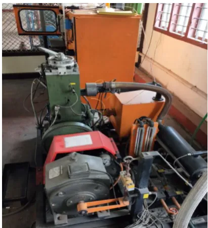
5. EXPERIMENTAL SETUP
The variable compression ratio (VCR) diesel engine used to conduct the experiments in single cylinder, four stroke, water cooled, direct injection engine. Two main components from main parts of the test rig, Welded steel base plate and Eddy Current Dynamometer provided with cooling water arrangement. Panel board positioned over the base plate consists of fuel system with flow measurement by burette, air flow measurement system, and temperature and speed indicator. The loading device used is an Eddy Current Dynamometer of matching capacity to load the engine up to HP at 1500 RPM. The following instrumentation is provided,
U-tube manometer for air flow
Digital temperature indicator- multi point indicator with thermocouples.
The test rig is arranged for manual control with hand cranking start arrangement for engine starting. Fuel Measuring Arrangement consists of
fuel tank, burette and suitable stopwatch and supplied with fuel piping from fuel tank to Engine. Heat carried away by cooling water consists of suitable inlet and outlet piping with flow control valve. Rotometer is meant to measure the rate of flow of cooling water and thermocouples for measuring inlet and outlet water temperature. The equipment is instrumented so that the following experiments could be performed,
Brake Thermal Efficiency,
BP Measurement,
Fuel Consumption Measurement,
Air Intake Measurement.
5.1 ENGINE SPECIFICATIONS
The figure below represents the Variable Compression Ratio experimental test setup.
[image:5.595.330.536.501.726.2]© 2019, IRJET | Impact Factor value: 7.211 | ISO 9001:2008 Certified Journal
| Page 581
Table -1: Engine SpecificationsEngine KIRLOSKAR DIESEL
ENGINE
Type Water Cooled
Injection Direct Injection (DI)
Maximum Speed 1500
Number of Cylinder one
Bore 80mm
Stroke 110mm
Cubic Capacity 0.553 litre
Maximum HP 5 HP
Loading Eddy control Dynamometer
Injection Pressure 190 bar
5.2 ENGINE LAYOUT
Fig -3 Layout of VCR engine CONTROL PANEL
a – fuel measuring burette
b – U tube manometer
c – Air box with sensors
d – Temperature indicator
e – Speed indicator
f – Load indicator VCR ENGINE
g – fuel filter and pump
h – Fuel line pressure sensor
i – Fuel injector
j – Combustion analyser ROTOMETER
1. Engine water supply 2. Calorimeter water supply
ENGINE EXHAUST LINE
k – AVL 5 gas analyser 1. AVL smoke meter
5.3 COMPUTERIZED DATA ACQUISITION
MEASUREMENT
Table -2: Computerized Data Acquisition Measurement
Fuel flow Burette with sensor
Air flow Digital Differential
Manometer
Crank angle Crank angle Encoder
Engine speed Sensor
Engine torque Load cell
Temperature Thermocouple
Cylinder pressure Combustion pressure sensor
6.EXPERIMENTAL WORK
6.1 FABRICATION OF REACTOR
6.1.1 COMPONENTS AND DESCRIPTION
The major parts of the pyrolysis reactor are described below
1.
REACTOR
© 2019, IRJET | Impact Factor value: 7.211 | ISO 9001:2008 Certified Journal
| Page 582
Fig -4 Reactor2.
FURNACE
The furnace provides the heat the reactor needs for pyrolysis to take place , it has a thermocouple to control the temperature. Afurnaceis a device used for high-temperature heating. The name derives fromGreekwordFornax, which means oven.
Fig -5 Furnace
3.
CONDENSER
It cools all the heated vapour coming out of the reactor. It has an inlet and outlet for cold water to run through its outer area. This is used for cooling the vapour. The gaseous hydrocarbons at a temperature of about 35OoC are
condensed to about 30-35oC.
In systems involvingheat transfer, a condenseris a device or unit used to condensea substance from itsgaseousto itsliquidstate, by cooling it. In so doing, thelatent heatis given up by the substance, and will transfer to the condenser
coolant. Condensers are typicallyheat exchangerswhich have various designs and come in many sizes ranging from rather small (hand-held) to very large industrial-scale units used in plant processes. For example, a refrigeratoruses a condenser to get rid of heatextracted from the interior of the unit to the outside air. Condensers are used in air conditioning, industrialchemical processessuch asdistillation, steampower plantsand other heat-exchange systems. Use of cooling water or surrounding air as the coolant is common in many condensers.
Fig -6 Condenser
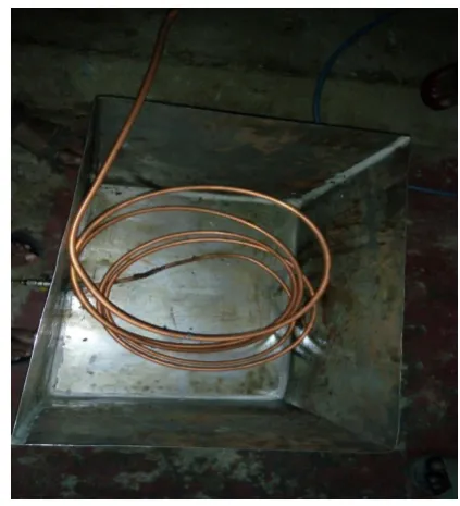
4.
COPPER TUBES
[image:7.595.81.246.90.297.2] [image:7.595.318.530.219.452.2] [image:7.595.49.221.404.603.2]© 2019, IRJET | Impact Factor value: 7.211 | ISO 9001:2008 Certified Journal
| Page 583
Fig -7 Copper tubes5.
HEATING ELEMENT
Aheating elementconverts electricity into heat through the process of resistive orJoule heating.Electric currentpassing through the element encounters resistance, resulting in heating of the element. Unlike thePeltier Effectthis process is independent of the direction of current flow.
6.2 COLLECTION OF RAW MATERIALS
Raw materials for the production of waste plastic oil is the mixed waste plastics. It needed to shred the plastics into small pieces for pyrolysis. As part of CLEAN KERALA MISSION, TVM, about 10kg of shredded waste plastics were collected. Figure below shows plastic shredding unit.
Fig -8 Plastic Shredding Unit
6.3 EXTRACTION AND FILTERATION
Raw material (shredded plastics) was then fed in the reactor and heated by means of electrical energy. The yield commenced at a temperature of 3500C. The gaseous products
resulting from the pyrolysis of the plastic wastes is supplied through the copper tube. Then the burned plastic gas condensed in a water cooled condenser to liquid fuel and collected for experiment. The extracted oil was filtered by using grade 4 filter paper.
Fig -9 Waste Plastic Oil
[image:8.595.312.520.64.344.2] [image:8.595.35.294.95.355.2] [image:8.595.323.499.512.730.2]© 2019, IRJET | Impact Factor value: 7.211 | ISO 9001:2008 Certified Journal
| Page 584
water cooled, direct injection, variable compression ratioengine
6.4 COMPARISON OF PROPERTIES
Table -3: Comparison of properties
7.RESULTS AND DISCUSSIONS
7.1 PERFORMANCE CHARACTERISTICS
7.1.1 LOAD VS BRAKE POWER
Chart -1: Load vs Brake Power
The above graph represents the variation of brake power of various blends at different compression ratio. From the graph it is clear that the brake power increases with increase in load. That is load and brake power are proportional to each other. That is why the plot shows a linear characteristic. As it shows that among the blends diesel at compression ratio 18 is found to have maximum brake power at an intermediate load. At higher load brake power for various blends are comparable. Among the blends, diesel at compression ratio 18 has the highest value of brake power at a load of 4 kg and the value is about 1.5 kW.
7.1.2 LOAD VS BRAKE THERMAL EFFICIENCY
Chart -2: Load vs Brake Thermal Efficiency
The variation of brake thermal efficiency of the engine with various blends is shown in figure and compared with brake thermal efficiency obtained with diesel. Among the blends 16CRP15 ,that is 15% WPO and 85% DF at compression ratio 16 is found to have the maximum thermal efficiency of 27.57 at a load of 6 kg while for diesel it was 23.27% at compression ratio 16 and 24.34% at compression 18. It was observed that brake thermal efficiency of 16CRP15 is found to be higher than diesel at all load levels.
PROPERTY WPO DF
Density at 30ºC
(gm/cc) 5 0.835 0.840
Calorific value (kJ/kg) 44.34
0 0 46.50
Viscosity at 40 ºC (Cst) 2.52 2
Cetane number 51 55
Flash point (ºC) 42 50
Fire point(ºC) 45 56
© 2019, IRJET | Impact Factor value: 7.211 | ISO 9001:2008 Certified Journal
| Page 585
7.1.3 LOAD VS SPECIFIC FUEL CONSUMPTION
Chart -3: Load vs Specific Fuel Consumption
Above figure shows the variation specific fuel consumption of various blends. Among the various blends 16CRD100 is found to have the least specific fuel consumption, that is 100%DF at compression ratio 16 has more fuel economy. All other blends are higher than the diesel fuel. The specific fuel consumption became significant at the higher loads only. The values of specific fuel consumption get decreased from the low loads and become almost constant. The reason behind this general trend is given below.
Specific fuel consumption means the effectiveness to convert the chemical energy contents of fuel into useful work. So this engine index is used rather than thermal efficiency to indicate not only the efficiency of engine combustion process, but also fuel economy. At high engine speed the fuel combustion is improved due to better mixing of fuel and air. While at high engine load the combustion is improved due to higher in-cylinder temperature after successive working of engine at this load that is would improve fuel atomization and evaporation processes and partially improve fuel air mixing process.
7.1.4 LOAD VS VOLUMETRIC EFFICIENCY
Chart -4: Load vs Volumetric Efficiency
Above figure shows the load vs volumetric efficiency. Volumetric efficiency is nothing but breathing capacity of engine. As we know in normal engine (without charging) air is fed to the engine with the help of atmospheric pressure. As the piston moves from TDC to BDC pressure inside the cylinder drops below atmospheric and air/charge is sucked in. Volumetric efficiency of reciprocating engine is poor at high speed due to the less time available for suction stroke. With the increasing speed time available lessens and volumetric efficiency falls. At higher load volumetric efficiency is high for blend 18CRP15. That is 15% WPO and 85% DF at compression ratio 18 having the highest value of volumetric efficiency of 78.43%. All other blends are comparable at all levels of lower loads.
© 2019, IRJET | Impact Factor value: 7.211 | ISO 9001:2008 Certified Journal
| Page 586
7.2 EMISSION CHARATERISTICS
7.2.1 LOAD VS OPACITY
Chart -5: Load vs Opacity
Opacity is the degree to which smoke blocks light, and the basis for measuring the amount of smoke coming from a diesel-powered vehicle. Poorly maintained or malfunctioning engines are sometimes the cause of excessive smoke. Above figure shows the variation of opacity against load for various blends. Among the various blends 16CRP15 has the least value of opacity. That is 15% WPO and 85% of DF at compression ratio of 16 having a value of 54.1% at higher load.
8.CONCLUSION
Experimental analysis of all the blends have shown a marginal increase in brake thermal efficiency at higher loads while there was an appreciable increase in fuel consumption at all the loads compared to diesel. Opacity for the blends are lower than that of diesel fuel. Among them 16CRP15 is found to have least opacity value.
1. Smooth working of engine is observed with waste plastic oil by blending with diesel without any engine modification.
2. Brake power for all the blends are comparable with diesel at different loads.
3. Slight increase in Brake Thermal Efficiency.
4. Specific Fuel Consumption is slightly higher than that of diesel.
5. At higher load volumetric efficiency is higher for blend 18CRP15.
6. 16CRP15 blend has the least value for opacity.
REFERENCES
[1] Krishna chaitanya. A.V, Girish. S, Monica.T. Experimental
investigations on variable compression ratio diesel engine fuelled with mahua oil and diesel blends, International Journal of Civil Engineering and Technology, 8(4), 2017, pp. 313-324.
[2] E. C. Prasad Nidumolu, K. Sandeep Kumar and Dr. J.
Krishnaraj, Performance and Emission Analysis of CI engine fuelled with the blends of Palm methyl esters and diesel, International Journal of Mechanical Engineering & Technology (IJMET), Volume 08, Issue 6, June 2017, pp. 704-713.
[3] Bridjesh.P, Prabhu kishore.N. Performance analysis of
variable compression ratio diesel engine using calophyllum inophyllum biodiesel, Indian journal of science and technology, 9(35), 2016, DOI: 10.17485/ijst/2016/v9i35/95577.
[4] I. López a, C.E. Quintana b, J.J. Ruiz c, F. Cruz-Peragón d,
M.P. Dorado c, Effect of the use of Olive–Pomace oil biodiesel/diesel fuel blends in a compression ignition engine: Preliminary exergy analysis ,Energy Conversion and Management 2014: 85: 227–233.
[5] Nilamkumar. S. Patel,Keyur D. Desai,Waste Plastic Oil As
A Diesel Fuel In The Diesel Engine:A Review,International Journal of Engineering Research & Technology,ISSN: 2278-0181,2(3),2013,pp. 1-6.
[6] Sandeep kumar. K, NEC Prasad and P. Bridjesh. Effect of
mahua oil methyl ester with additive as an ic engine fuel in combination with diesel in ci engine: an experimental investigation, International Journal of Mechanical Engineering and Technology (IJMET) Volume 8, Issue 5, May 2017, pp. 1084–1091.
[7] ] R Karthik, Angelin C Pushpam, and M. C. Vanitha and D.
Yuvaraj. Elimination of Methylene Blue from Aqueous Solution Using Biosorbents under Stirring and Stagnant Conditions. International Journal of Advanced Research in Engineering and Technology, 6 (10), 2015, pp. 76-85.
[8] A.V. Krishna Chaitanya, S.Girish and T. Monica.
Experimental Investigation On Variable Compression Ratio Diesel Engine Fuelled With Mahua Oil and Diesel Blends. International Journal of Civil Engineering and Technology 2017, 8 (4),2017 pp. 313–324.
[9] Venkata Ramesh Mamilla and M.V. Mallikarjun. Biodiesel
production from palm oil by transesterification method International Journal of Current Research, August, 2012 Vol. 4, Issue 08, pp. 083-088.
[10] Ayush Srivastava Effect of Fuel Type and Engine
Parameters on Performance and Emission Characteristics of A Spark Ignited Direct Injection Engine. International Journal of Advanced Research in Engineering and Technology, 8(3), 2017, pp 19–24.
[11] E.C. Prasad Nidumolu, K. Sandeep Kumar and Dr. J.
© 2019, IRJET | Impact Factor value: 7.211 | ISO 9001:2008 Certified Journal
| Page 587
BIOGRAPHIES
Prenav T Nair
Student, Department of Mechanical Engineering , Musaliar College of Engineering and Technology, Pathanamthitta, Kerala, India
Jumin S Thomas
Student, Department of Mechanical Engineering , Musaliar College of Engineering and Technology, Pathanamthitta, Kerala, India
Krishnarag S
Student, Department of Mechanical Engineering , Musaliar College of Engineering and Technology, Pathanamthitta, Kerala, India
Karthik Das P
Student, Department of Mechanical Engineering , Musaliar College of Engineering and Technology, Pathanamthitta, Kerala, India
Vipin R
Assistant Professor, Department of Mechanical Engineering , Musaliar College of Engineering and Technology, Pathanamthitta, Kerala, India