camera steering:
robotic versus human controlled
– A phantom study
November 2016 – November 2017
Clinical internship Master 3 Technical Medicine
Lennert Molenaar
Abstract
Introduction: With the introduction of endoscopic surgery, patient healthcare changed significantly. The main improvement of laparoscopic operations compared to open surgery is better patient outcome. However, it is important to understand the added burden laparoscopic surgery brings to the surgeon and his/her assistant. To overcome this burden, multiple robotic innovations were introduced, such as active robotic camera holders. Multiple active holders are available for quite some time; however, all interrupt the flow of the operation. This study focuses on one new active camera holder; the AutoLap. The AutoLap can be either controlled by a joystick or by a unique image analysing software function called go-to mode. The main question of this thesis: “Is the go-to mode the long-sought solution for active camera steering, utilising the advantages of robotics without disturbing the flow of the operation?”
Methods: This trial is a phantom study, comparing the execution time and path length of three steering modes (human, joystick and go-to). The aim is to evaluate the effectiveness of the AutoLap. Four test subjects will be enrolled and will perform multiple times two series of camera steering exercises with all three modes. Execution time and path length will be measured, the first 50% of the execution time results will be compared with the second 50% to draft a (possible) learning curve. Furthermore, validated questionnaires will be filled in to measure the subjective experience.
Results: Human controlled steering is superior in terms of execution time and path length, followed by go-to controlled and lastly joystick controlled (45.0, 114.2 and 122.1 seconds respectively). Joystick controlled steering shows the steepest learning curve (140.7 vs. 117.7) followed by human controlled (48.6 vs. 42.8) and go-to controlled (121.0 vs. 115.5). The questionnaires show similar results for human and go-to controlled, joystick controlled scores lower.
Acknowledgements
During the second year of the master of Technical Medicine, I completed four internships of ten weeks at three different hospitals and at a mechatronics company. To conclude my master and graduate from the University of Twente, I’ve decided to spend my final internship of forty weeks in Meander Medical Centre, Amersfoort. The result is this thesis, which wouldn’t have been possible without the aid of several of people.
I would like to thank Ivo Broeders for always giving new insights and an honest, critical but also fair opinion. I received a lot of freedom this past year to develop the given assignment to my own view and to develop myself further in the clinical and technical field. For me personally, this was the best approach possible, for which I’m grateful. I also greatly enjoyed the extracurricular activities, such as the Frankfurt congress and the winter meeting in Austria.
Ferdi van der Heijden for giving Matlab solutions I didn’t think possible, and pushing me to train myself further in Matlab. I’ve never been the greatest Matlab programmer, but during the past year I developed a reasonable fair insight in the workings of the program. I also enjoyed our Matlab
troubleshoot sessions, few things are as rewarding as finding small mistakes in your script after several days of looking.
Paul Wijsman for all his feedback, medical explanations and overall support. Paul, working with you for the past year on three projects was both very instructive and nice. I think we really did some great work and I’m sure your promotion reaps the benefit of our collaboration. Also, I think it is important to keep meeting now and then, to eat a burger and drink a beer.
All the medical personal in Meander Medical Centre for receiving me with open arms. I attended a lot of surgeries, an evening and night shift, multiple consultation hours, etc. At all these occasions, I received clear explanations (spontaneously and when asked for) and helped me to (greatly) increase my medical knowledge and expertise.
Paul van Katwijk for teaching me the benefit of self-reflection. During the bachelor, I never was one for reflection, to be honest I kind of had the feeling that it was a waste of time. But, during the second and third year of master I gradually came to understand the benefit of our sessions and really started to enjoy them.
Graduation committee
Chairmen: Prof. Dr. I.A.M.J. Broeders1, 2
Medical supervisor: Prof. Dr. I.A.M.J. Broeders1, 2
Technical supervisor: Dr. Ir. F. van der Heijden2
Process supervisor: Drs. P.A. van Katwijk3
Outside member: Dr. Ir. B. ten Haken4
Extra member: Drs. P.J.M. Wijsman1
1. Meander Medical Centre, Department of Surgery, Amersfoort, The Netherlands
2. University of Twente, Department of Robotics and Mechatronics, Enschede, The Netherlands
Table of contents
01. Introduction ... 1
1.1 Clinical background ... 1
1.1.1 Anatomy of the abdomen ... 1
1.1.2 Open vs. minimal invasive surgery ... 3
1.2 Problems associated with laparoscopy ... 3
1.3 Current solutions ... 3
1.3.1 Passive camera holders ... 3
1.3.2 Active camera holders ... 4
1.4 Research proposition ... 5
02. Methods ... 7
2.1 Study setup ... 7
2.2 Study population ... 10
2.3 Study parameters ... 10
2.3.1 Main study parameters/endpoints ... 10
2.3.2 Secondary study parameters/endpoints ... 10
2.4 Statistical analysis ... 10
2.5 Technical background ... 11
2.5.1 Camera calibration ... 11
2.5.2 Path length calculation ... 12
2.5.3 Go-to mode algorithm ... 14
03. Results... 15
3.1 Phantom production ... 15
3.1.1 Phantom organ production ... 15
3.2 Main study parameters outcome... 18
3.2.1 SURF algorithm results ... 20
3.3 Secondary study parameters outcome ... 22
04. Discussion ... 23
05. Conclusion ... 25
5.1 Future recommendations ... 25
06. References ... 26
07. Appendices ... 29
7.1 Path length calculation through different approaches ... 29
7.1.1 Object detection and recognition ... 29
7.1.2 SURF algorithm in combination with 3D reconstructed photography ... 32
7.1.3 Discussion & conclusion ... 34
7.2 NASA TLX questionnaire ... 35
7.3 SMEQ questionnaire ... 36
7.4 Questionnaire box plots, Mauchly’s test ... 37
List of abbreviations and relevant definitions
AutoLap Active robotic camera holder
Active camera holder Laparoscopic camera holder with an active positioning system Blob features Detection of regions in images that differ in colour or brightness EM-tracking Electromagnetic tracker, device using an electromagnetic field to
measure the X, Y and Z-coordinates (world coordinates) of a chosen point
Follow-me mode AutoLap control method where the camera tracks the tagged instrument
Go-to mode AutoLap control method where the camera tracks the desired tagged location
Joystick mode AutoLap control method where the camera is controlled by joystick Kolmogorov-Smirnov test Statistical test to determine if your data is normal distributed Machine learning Application of artificial intelligence to build an analytical model by
using algorithms
Matlab Mathematical software used to analyse and calculate path length Mauchly’s test Statistical test to determine if the variance of your groups is similar
MST Medical Surgery Technologies
NASA-TLX NASA-Task Load Index (validated questionnaire)
One-way repeated Statistical test used to compare three (or more) group means where measures ANOVA test the participants are the same in each group
OR Operating Room
Passive camera holder Laparoscopic camera holder with no positioning system
Pixel coordinates Coordinates of a chosen point in an image, expressed in rows and columns of the inserted image
PUR-foam Polyurethane foam
SD Standard Deviation
SURF Speeded-Up Robust Features, algorithm to find blob features SMEQ Subjective Mental Effort Questionnaire (validated)
SolidWorks Solid modelling program for computer designing and engineering SPSS Statistical Package for the Social Sciences, analytical software used to
calculate power and significance
01.
Introduction
1.1
Clinical background
With the invention of the endoscope at the start of the 20th century, patient healthcare changed
significantly. [2] Initially, laparoscopy was not very successful and did not have clinical utility other than a diagnostic aid. At the end of the 1980s, the first laparoscopic interventions were successfully conducted, starting the dawn of minimal invasive surgery. These laparoscopic interventions lead to a better patient outcome compared to open surgery. [3-8] More recently, robotic innovations changed the landscape even more, leading to a less invasive and more controlled and precise manner of operating with improved ergonomics. [2]
1.1.1 Anatomy of the abdomen
To successfully perform surgery (open or laparoscopic), extended anatomical knowledge is essential. Most of the laparoscopic surgeries takes place in the trunk, this thesis will mainly focus on its lower part; the abdomen (Figure 1 & 2). The abdomen can be viewed as a flexible dynamic container for the gastrointestinal organs. [9] This ‘container’ is protected by
abdominal walls anterolaterally, the pelvic muscles caudally and the diaphragm cranially. The major organs inside are the liver, gallbladder, kidneys, stomach, duodenum, pancreas, spleen, large and small intestines, urinary bladder and male and female
reproductive organs. In addition, the aorta and inferior vena cava are running through the abdomen. The thoracic skeleton cranially and pelvic girdle caudally are linked by the vertebral column and support the abdominal muscles. This construction gives
protection as well as flexibility, needed for respiration and locomotion. The abdomen is also able to generate pressure to ensure expulsion of air and bodily fluids.
The abdominal walls consist of multiple fascia and muscles and can be divided into the anterolateral abdominal wall (consisting of the anterior wall and right and left lateral walls) and posterior wall. The subcutaneous tissue over most of the wall includes a variable amount of fat. Right beneath the skin (subcutaneous) the superficial fatty layer (camper fascia) and the deep membranous layer (scarpia fascia) are located (Figure 1B). Furthermore, a total of five muscles, three flat muscles (external oblique, internal oblique and transversus abdominis) and two vertical muscles (large rectus abdominis and small pyramids) are present.
The external oblique muscles are the largest and most superficial of the three flat muscles. It runs diagonal from the ribs to the linea alba, pubic tubercle and the iliac crest (Figure 3A). Perpendicular beneath the external oblique runs the internal oblique muscle from the iliac crest to the ribs and linea alba (Figure 3B). The third muscle layer is the transversus abdominus, which runs horizontal from the costal cartilages to the linea alba (Figure 3C). The linea alba runs vertically along the length of the abdominal wall and separates the bilateral rectus abdominis.
skin. It also contains the umbilical ring, a defect which passed the foetal umbilical vessels, umbilical cord and placenta.
[image:10.595.99.500.113.462.2][image:10.595.78.516.493.761.2]
1.1.2 Open vs. minimal invasive surgery
As mentioned before, the main improvement of laparoscopic operations is better patient outcome compared to open surgery. This conclusion is seen in general when open surgery is compared with laparoscopic surgery. [3-8] Laparoscopic surgery is associated with less pain, less blood loss, faster recovery and a shorter hospital stay. A systematic review from the Cochrane library [3] compares thirty-eight trials with 2338 cholecystectomy patients in total. It concludes that there are no
significant differences in mortality, complications and operative time between open and laparoscopic surgery. However, laparoscopic cholecystectomy is associated with a faster recovery and thus
significantly shorter hospital stay. Mentioned advantages ensure that laparoscopic surgery is the preferred method of operating. However, it is also important to understand the added burden laparoscopic surgery brings to the surgeon and assistant.
1.2
Problems associated with laparoscopy
To understand the need for robotic innovations, it is necessary to understand the difficulties of modern laparoscopic surgery. During the development of minimal invasive surgery, the focus was on the wellbeing of the patient. However, in recent years, focus has shifted towards the wellbeing of the physicians during laparoscopic interventions by analysing the drawbacks. Well known difficulties are a long and steep learning curve, limited possible motion, loss of degrees of freedom, unstable video footage, poor ergonomics and two-dimensional imaging. [2] Of these problems listed, multiple are caused by camera steering and the manner of operating. Since the camera is being controlled by an assistant, the surgeon must verbally command his/her assistant how to manoeuvre the camera. Also, work space is limited; the surgeon and his/her assistant can get in the way of each other. This may result in frustration and a bad posture, which can negatively influence the outcome of the operation. In conclusion, today setting is not optimal and there is room for improvement.
1.3
Current solutions
To overcome some of these problems, multiple robotic innovations were introduced. [10-40] The most successful robotic solution thus far is the da Vinci system of Intuitive Surgical. This machine places the surgeon behind a console and replaces the camera operator and improves ergonomics, image quality and surgical precision. [10-15] Since the da Vinci system is expensive, simpler smaller systems were developed with focus on improving the camera operation during endoscopic
interventions. Of all these camera control solutions, none could replace the human camera control. A possible explanation is the manner of how robotic camera steering devices are controlled (eyeball tracking, head movement tracking, verbal commands, footswitch, joystick control). These current methods of steering are successful but not without disturbing the flow of the operation. Distraction by the device and the need for refocussing on the operation after steering the camera are the main issues surgeons face with current robotic systems. It is evident that a robotic camera holder is needed, but it is vital that the manner of controlling is intuitive, fast and does not require active thinking.
1.3.1 Passive camera holders
1.3.2 Active camera holders
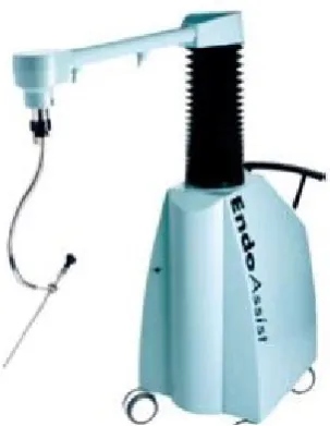
[image:12.595.98.250.298.486.2]Like passive camera holders, active camera holders hold the camera, but can also manipulate the position of the camera directly without manual adjustments. There are multiple active camera holders, some well researched. Well known active holders are the AESOP [17-19, 21-29] (Figure 5), EndoAssist [19, 26, 29-32] (Figure 6), ViKY [19, 22, 33], Soloassist [19, 34, 35], Lapman [18, 19, 36, 37], Freehand [19, 38, 39] and Naviot [40]. The manner of controlling differs per device, for example the AESOP can be controlled by voice, hand or footswitch, the EndoAssist by head movements (by a helmet) and the Lapman and Freehand through an instrument mounted joystick. The positioning of the device also differs between floor-mounted or bed-mounted. The mentioned advantages for passive camera holders (reducing one OR assistant, improved ergonomics, more stable camera view and controlment of one’s own view) hold as well for the active camera holders. Even though the camera no longer needs to be manually operated, the manner of controlling in above mentioned active camera holders is not intuitive enough. The surgeon is too much distracted by manoeuvring the camera and needs to refocus on the operation. This is the reason no active camera holder has achieved the success the da Vinci has.
[image:12.595.383.502.304.500.2]Figure 4: Example of the Endofreeze
Figure 5: Example of the AESOP
[image:12.595.222.374.537.733.2]1.4
Research proposition
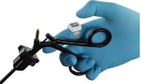
A possible solution for this problem could be the AutoLapTM system of Medical Surgery Technologies
(MST). This robotic arm controls the camera during an endoscopic operation (Figure 7) using a wireless sterile joystick (Figure 8). [41] The main difference between the AutoLap and other existing systems is the active image analysis software. This unique ‘smart’ software utilizes the input images of the camera and the input of the surgeon to move the camera to the desired location. There are two alternate applications: the “follow-me mode” and the “go-to mode”. The go-to mode enables the surgeon to use an instrument to tag the new desired centre field of view and release the button of the remote controller. The field of view will then be centred around the virtually marked new position, at a comparable distance from the tissue. By using this mode, it is possible for the surgeon to control the camera directly, without instructing an assistant.
As of this point, human camera control is still preferred by the medical community, despite known disadvantages. Active robotic camera holders are theoretically attractive, but in practise disrupt the flow of the operation too much.
The main question of this thesis: “Is the go-to mode the long-sought solution for active camera steering, utilising the advantages of robotics without disturbing the flow of the operation?”
This thesis will chronologically explain in detail the steps taken to answer posed research question. To answer this question, two sub questions arise:
- How does the go-to mode of the AutoLap perform in comparison with joystick and human camera steering?
- Is the solution the go-to mode offers also the desired solution, or is something else needed?
Figure 7: Example of the AutoLap of Medical Surgery Technologies
[image:14.595.186.412.407.542.2]02.
Methods
2.1
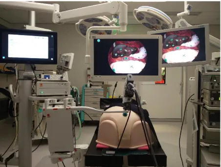
Study setup
This trial is a phantom study, comparing the execution time and path length of three steering modes: human operators, joystick operators and go-to mode operators. The aim is to evaluate the
effectiveness of the AutoLap, specifically the go-to mode. The test subjects have conducted a series of camera steering exercises with all three modes. The order at which mode has been performed first, second and third has been determined in a randomized fashion; every subject executed every possible sequence, before repeating this.
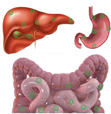
The steering exercises consisted of a series of markers placed on the phantom organs, which have been navigated to with the camera by the test subjects. A screen marker was added on the operating screen which needed to be positioned on a phantom marker, the supervising investigator decided when the test subject could navigate to the next point. This marker consists of a green dot
surrounded by four rectangles (which create a square, Figure 10). When operating the camera through human mode or joystick mode, the green dot had to be navigated inside a green phantom marker. When using the go-to mode, the green phantom marker had to be navigated inside the square. This square represents the invisible circle (with radius 5% of the screen) of the go-to mode, which will be further explained in chapter 2.5.3. In this way, both human mode and joystick mode are equally comparable with the go-to mode. Also, the choice was made to only move camera controls in the X- and Y-direction. In this situation, movement in the X- and Y- direction correspond with
left/right and up/down camera steering, the Z-direction corresponds with the level of camera zoom. For human control, steering in X-, Y-, and Z-direction can be executed simultaneously in one
movement. But, with the AutoLap as active camera holder, this isn’t possible. To adjust the Z -direction, a second action must be executed, namely pressing the button of the joystick. When excluding the use of the Z-direction, both human control and joystick/go-to mode control need only one action to move the camera, ensuring an equal comparison.
Every session has been recorded to measure the execution time and path length. After every session, the recording was edited, such that the beginning and ending of the video is equal to the beginning and ending of the steering exercises. The length of the video and the execution time are then alike and can be noted, no further processing has been needed. To calculate the path length, it was necessary to know the real-time position of the laparoscopic camera. To measure the position, the SURF algorithm available in Matlab has been utilised (which will be further explained in chapter 2.5.2.1). When this was realised, the path length has been calculated by adding the distance between every previous and next camera position. The focus of this research is on the analysis of the go-to mode, but during this study it became evident that the calculation of the path length with the chosen study setup is no easy task. For this reason, a separate smaller research has been conducted into varying possible solutions for this problem. The SURF algorithm is the main solution and will be used and explained in this thesis. However, appendix 7.1 explains and discusses these other solutions.
controlled the camera and one operating instrument. In case of human mode however, the test subject was placed on the left side of the phantom to control the camera, the operating instrument was controlled by the supervising investigator. In this way, realistic operating conditions were created. Figure 11 shows the final instrumental study setup.
By analysing the execution time throughout all the exercises, a learning curve for every camera control mode was drafted. The first 50% of the results were compared with the second 50% of the results, showing if there is a learning curve. The path length has not been used as parameter for the learning curve, expectation was that only small differences between control modes will be present. The user experiences show the general attitude towards human controlled steering and using the AutoLap and thus if practitioners are willing to use it.
Primary objectives - Execution time - Path length
Secondary objectives
[image:16.595.86.512.302.738.2]2.2
Study population
To be eligible to participate in this study, subjects met the following criteria:
- Subject who assisted or performed during at least twenty laparoscopic operations (from Meander Medical Centre)
A potential subject who met the following criteria were excluded from participation in this study: - Incomplete execution of the camera steering exercises
In total, 4 participants were included in this study.
2.3
Study parameters
The same phantom for every session was used with custom made 3D printed organs. These organs were painted to achieve a realistic effect. The positioning of the phantom, AutoLap and team (test subject and investigator) were standardized and the same verbal commandos were given during the session. Before the start of the session, the setup of the phantom and system were tested by the investigators, as well as the correct functioning of the AutoLap system.
To measure the differences between physical and mental distress between the modes, multiple questionnaires were filled in after each training session. The NASA TLX and SMEQ validated questionnaires were used.
2.3.1 Main study parameters/endpoints
The main study parameter is the difference between execution time and path length. All three modes were compared using these two parameters. The path length was measured in three dimensions (X, Y and Z). To accurately measure these two parameters, Matlab software has calculated these by the recorded video images.
2.3.2 Secondary study parameters/endpoints
The secondary study parameters are the results from the SMEQ and NASA TLX questionnaires. These results show the general attitude towards the AutoLap and thus if practitioners are willing to use it. Also, comparison between the first 50% and second 50% of the execution time results was done, to give an overview in learning similarities/differences between the different modes.
2.4
Statistical analysis
The expected study parameters are execution time, path length and questionnaire results. The data is statistically analysed to determine whether one of the three modes prevails. The three study parameters are analysed one by one, individually. In such an analysis, a study parameter is regarded as an independent variable with three levels: human mode, go-to mode and joystick mode. The data is continuous and there are no jointly considered variables. For this reason, the chosen analysis is the one-way repeated measures ANOVA test, based on mentioned input variables. To perform this test correctly, three assumptions are made; there may be no outliers present (outliers can be deleted based on boxplots of the mean with standard deviation), the data is normal distributed (based on the Kolmogorov-Smirnov test, p≥0.05) and the variance of the groups must be similar (based on
2.5
Technical background
During a camera steering exercise, the video images are captured to calculate the path length. First the 3D trajectory (the path) of the camera is calculated for which several design considerations are to make, and different steps to be taken. From this 3D path, the path length is calculated. The
calculations are done with Matlab. The chosen solution will be explained step by step in the following sections.
2.5.1 Camera calibration
To correctly calculate the path length, it is important to calibrate the camera. The internal camera calibration parameters consist of a 3x3 calibration matrix and of lens distortion parameters. The calibration matrix defines the focal distance, the aspect ratio for non-square pixel sensors, and the camera centre. [42] The calibration matrix is needed for the calculation of the 3D path, which will be further explained in section 2.5.2.2.
A possible camera distortion consists of radial, tangential (also known as decentering distortion) and thin prism lens distortion. [43, 44] Radial distortion occurs as increased or decreased image
magnification with distance from the optical axis. Tangential distortion arises when the camera lens and the camera sensor are not perfectly parallel to each other. Thin prism distortion happens when the lens is tilted, it is not perpendicular to the optical axis. After calibrating the camera, radial and tangential distortion can be corrected.
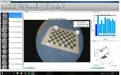
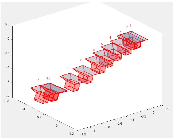
[image:19.595.92.507.445.701.2]The camera calibration is done with a camera-calibration application embedded in Matlab. To use this calibration app, at least 10 images of a checkerboard with known dimensions from different viewing angles is needed. With these images, Matlab calculates the lens distortion parameters, which can be used to undistort the image. Furthermore, this application estimates the calibration matrix. An example of the calibration app can be seen in Figure 12.
2.5.2 Path length calculation
To calculate the actual path length, the location of the laparoscopic camera at every moment is needed. The initial idea was to use optical tracking or electromagnetic-tracking (EM-tracking), available at Twente University. The tip of the laparoscopic camera can be tracked with these
methods and thus used to calculate the real-time position of the camera. However, it is not possible to use this equipment for several weeks in Meander Medical Centre. It was also impossible to execute the phantom measurements at the university (the AutoLap is also used in Meander Medical Centre on weekly basis). Instead, computer vision was used to calculate the camera position at each point in time, and from that the total camera path length.
There are two principles that can be used to calculate a 3D path of the camera from the sequence of frames. One possibility is to calculate the displacement of the camera between two subsequent frames. Using these two frames, the change of orientation of the camera (its 3D displacement between the acquisition times of these frames) can be calculated. For this principle, based on the so called ‘eight-point algorithm’ [45, 46], only a few corresponding landmarks in the two frames need to be found. To find the 3D path, the cumulative sum of the incremental displacements is calculated. This method, generally referred to as ‘visual odometry’ [47], has some limitations which will be explained later.
The second principle uses 3D landmarks in the scene with known positions. If these positions are represented in some world coordinate system, then detecting and locating these landmarks in an image allows to reconstruct the pose, position and orientation, expressed in world coordinates. This principle has the potential advantage that the path is calculated without accumulation of errors. However, it needs the detection and localization of the 3D landmarks in the image.
2.5.2.1 Visual odometry: path reconstruction using key points
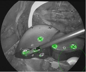
Visual odometry depends on the detection of 2D landmarks in the images, the so-called key points. Several algorithms are known from literature to detect these key points. [47-49]The applied algorithm in the current study is the Speeded-Up Robust Features (SURF) algorithm. This algorithm detects blob features. Key points that are detected in an image needs to be associated with key points that are detected in the next frame. This is called key point matching. After the laparoscopic camera is calibrated, a frame per frame comparison is executed through key points. The fifty strongest key points are calculated (Figure 13) and stored. Then key points of the next frame are calculated and matched with the stored key points from the first frame. All the corresponding key points from frame 1 and 2 are saved, the rest deleted. This comparing process is done for every frame (key points frame 2 compared with key points frame 1, key points frame 3 compared with key points frame 2, etc.).
With the matched key points of two consecutive frames, the rotation of the camera can be
2.5.2.2 Path reconstruction using 3D markers
To be able to relate the measured path length to a physical unit, the 3D positions of markers in the phantom are needed. This can be accomplished with a one-time measurement with the EM-tracking device ate Twente University (NDI Aurora). The accuracy of this system is about 1 mm. [50] The world coordinate system which is used for this is defined by the pose of magnetic beacon of the EM tracker, and as such is arbitrary.
To calculate the path length in millimetres, the 3D markers of the phantom must be linked with their 2D positions in a frame. With these pixel coordinates, and with the corresponding 3D world
coordinates of these markers, the pose of the camera can be calculated. [51] For this, the camera calibration matrix (obtained by calibrating the camera) is also needed. When executed for every frame, the calculated series of camera positions can be used to calculate the path length in world coordinates.
[image:21.595.124.473.405.698.2]The idea was to use the SURF algorithm to detect marker positions in the video using reference images of only the markers. The SURF algorithm was then applied to these reference images, but it appeared that the algorithm couldn’t detect these markers. A possible explanation is that the size of the given reference images was too small. But if a larger portion of a frame with the marker was given, the marker position estimation became inaccurate. Also, the markers are seen from different angles throughout the video images, making successful comparison with the reference images (which were made from just one angle) difficult. For this reason, it was not possible to calculate the path length in millimetres in this study setup. It was decided to use visual odometry instead.
2.5.3 Go-to mode algorithm
To better understand certain choices in this study, it is necessary to understand the go-to mode algorithm created by MST. This algorithm compares each frame with the previous frame and
measures the change of each pixel value. By doing so, the system can determine if (and if so, where) a moving object is present. When the go-to mode is activated, a green tag will be placed on the object with the greatest movement. In practise, when you move a surgical tool in the view of the camera and the go-to mode is activated, this tool will be tagged. It is then possible to move the tool to your region of interest and when arrived at the desired location to release the go-to mode; ordering the system to move the camera to your tagged region. When there is no (moving) tool present, a random object/place is tagged, leading to an unsuccessful camera placement (the camera will be moved to the spot indicated by the tracker, but chances are slim that this is the desired spot). Therefore, it is important (when using the go-to mode) to ensure your instrument is moving and correctly tagged. When moving the instrument at a very high speed (which you probably won’t do during surgery), it is also possible that the algorithm won’t tag the tool. The go-to mode enables a whole new manner of camera moving with the help of a smart algorithm, but it is necessary to first learn to operate the camera with this mode.
[image:22.595.146.451.68.307.2]Another point of interest of the go-to mode, is the inability of camera movement when a new desired location is tagged which lies within a 5% distance of the actual position. An invisible circle with a 5% diameter of the total resolution is present around the green tagger. Therefore, when placing your tagged instrument at your place of interest, the system will ensure that this tag will be inside the invisible circle centred at the middle of the screen. In other words, the system won’t exactly place the camera at the chosen point, but within a circle with a 5% screen radius. This was only discovered by tests in the phantom, during surgery this effect was never noticed (and not relevant). However, for this study setup it was something which had to be considered.
03.
Results
3.1
Phantom production
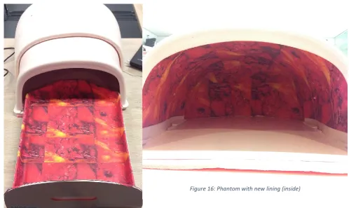
Before actual measurements could be conducted, first revision of the phantom and the production of the phantom organs was necessary. An abdomen phantom was available, but the inside of the phantom needed a more realistic lining. This was realized with printed canvas glued on the inside of the phantom (Figure 15 & 16).
3.1.1 Phantom organ production
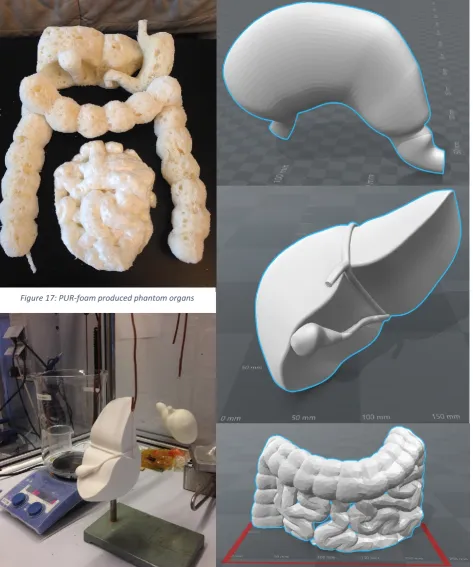
There are several possibilities to produce phantom organs (purchase at professional store, foam, casting, printing, etc.). To save costs, the first attempt to produce realistic phantom organs was done with polyurethane foam (PUR-foam). Two large blocks of PUR were made and cut in resemblance of the stomach, liver, gallbladder and small and large intestines (Figure 17). Hereafter, to achieve more realistic looking organs, the need to paint the PUR organs arose. To paint PUR, first every opening should be filled in and made smooth. This process is very time consuming and expensive, and thus deemed not worth the effort. Another solution was needed.
Realistic looking organs were needed for this study to achieve a professional and realistic study approach. For this reason, the second attempt to produce phantom organs was done with 3D printing. First, suitable models were created and modified to the dimensions of the phantom (Figure 18). This was executed with SolidWorks. Also, care was taken to scale the organs to an appropriate ratio. After the phantom organs were printed, first further treatment was needed before painting was possible. 3D printing results in a model with a rough outside structure. Human organs are (generally) smooth and shiny when looked at during laparoscopic surgery. To transform the rough outside structure into a smooth and shiny surface, treatment with acetone gas was executed (Figure 19). In Figure 20 the stomach can be seen with a nice smooth and shining outside surface. The final
[image:23.595.59.558.192.489.2]Figure 15: Phantom with new lining
step was the painting of the organs, which was done with spray paint and an airbrush for the final touch (Figure 21). To ensure that the organs are placed in the phantom at the same location and orientation, fixation was used. Velcro was applied to the backside of the organs and on the bottom of the phantom. The final phantom setup is displayed in Figure 22.
Figure 18: 3D model of the stomach, liver and intestines Figure 19: Work setup for 3D model treatment with
[image:24.595.65.539.141.709.2]acetone gas
Figure 20: 3D printed stomach treated with acetone gas
Figure 21: 3D model of the stomach, liver and intestines after treatment with acetone gas and paint
3.2
Main study parameters outcome
Four subjects were included in this study and performed 93 measurements in total; subject one and two performed 30 measurements each, subject three performed 15 measurements and subject four performed 18 measurements. Each measurement consisted of performing the upper and lower phantom track with all three possible camera control types (human, joystick and go-to mode). In total, 558 recordings were made and edited to retrieve the execution time and path length per camera control type. As explained in the methods; the analysis of the videos was executed by using the SURF algorithm, which resulted in a dimensionless path length. All videos were edited so that only the parts needed for the measurement were included. The execution time is based on the length of the input video, and thus independent of the used algorithm to calculate the path length. In table 1 the mean execution time results of the four test subjects (separate and combined) of all three camera modes are shown. Interesting are the total mean results; 118.5, 45.2 and 128.7 seconds for go-to, human and joystick mode respectively. Also noteworthy are the differences between the first and second 50% results per mode. Go-to mode scores 121.0 and 115.5 seconds, human mode scores 48.6 and 42.8 seconds and joystick mode scores 140.7 and 117.7 seconds.
Table 1: Mean results of the execution time (in seconds) of all three camera modes (total and per 50%)
Mean execution time (seconds) Go-to total Go-to first 50% Go-to second 50% Human total Human first 50% Human second 50% Joystick total Joystick first 50% Joystick second 50%
Subject 1, n=30 114.0 112.6 114.9 42.6 46.9 39.7 126.6 131.9 123.1
Subject 2, n=30 104.5 103.9 104.9 48.0 52.0 45.3 117.3 126.9 110.9
Subject 3, n=15 137.7 147.6 126.3 42.3 42.5 42.0 160.7 191.4 125.7
Subject 4, n=18 133.3 141.4 125.2 47.5 50.6 44.4 124.7 136.2 113.2
Total mean 118.5 121.0 115.5 45.2 48.6 42.8 128.7 140.7 117.7 The values in table 1 are of all the study results. To determine if there are any outliers present in the data, boxplots were created. The values outside the boxes are considered outliers and should be excluded (Figure 23). With the outliers excluded, the one-way repeated measures ANOVA test can be executed on the data. But only if Mauchly’s test and the Kolmogorov-Smirnov test score higher than 0.05, which they do (0.220 and 0.200, 0.142 and 0.064 for go-to, human and joystick mode
Figure 23: Boxplots of the execution time mean values of go-to, human and joystick mode with their outliers
Table 2: Mauchly’s test to determine if the execution time data has similar variance
[image:27.595.99.493.616.768.2]3.2.1 SURF algorithm results
[image:28.595.105.493.94.296.2]Table 5 depicts the calculated path length. The path length is dimensionless and obtained with the SURF algorithm. It is not necessary to execute a statistical test on this data; since this path length is dimensionless, the values will only be used to determine which camera control mode has the shortest (human mode), middle (go-to mode) and longest (joystick mode) camera trajectory.
Table 5: Mean results of the path length (dimensionless) of all three camera modes (total and per 50%)
Mean path length (dimensionless) Go-to total Go-to first 50% Go-to second 50% Human total Human first 50% Human second 50% Joystick total Joystick first 50% Joystick second 50%
Subject 1, n=30 195.3 193.9 196.2 145.9 159.3 136.9 226.9 239.5 218.6
Subject 2, n=30 182.5 180.4 183.9 158.2 168.3 151.5 213.2 228.5 203.0
Subject 3, n=15 232.6 244.7 218.6 152.1 150.0 154.5 230.0 220.4 241.0
Subject 4, n=18 223.9 226.4 221.3 161.2 171.5 151.0 224.5 238.5 210.6
Total mean 202.7 204.0 200.7 153.8 163.1 147.2 222.5 232.7 215.6 The following figure shows six examples of the trajectory of the camera during the upper and lower tracks with the three camera control types (Figure 24). Small differences between trajectories can be seen, which could be caused by varying camera movement, varying looking angle and/or (small) calculation errors.
[image:28.595.69.527.422.525.2]a) b)
c) d)
[image:29.595.71.524.66.669.2]e) f)
Figure 24: Example of the camera trajectory in the upper and lower track with the three camera control types; a) upper track human controlled; b) lower track human controlled; c) upper track go-to mode controlled; d) lower track go-to mode
3.3
Secondary study parameters outcome
After each completed session, the test subjects also completed two questionnaires; the SMEQ and NASA TLX. The SMEQ questionnaire measures physical effort on a scale from 0 to 150. The NASA TLX questionnaire measures varying loads (physical and mental) on a scale from 1 to 21. In total, 31 SMEQ questionnaires and 31 NASA TLX questionnaires were completed. The mean results of all four test subjects are shown in Figure 25. These results show that the SMEQ, physical demand, temporal demand and effort scores are lowest for go-to mode (23.6, 2.5, 4.5 and 4.0 respectively). The mental demand, performance and frustration scores are lowest for human mode (3.0, 3.5 and 2.7
[image:30.595.72.524.206.503.2]respectively). Joystick mode scores highest, except for physical demand.
Figure 25: Mean results of the SMEQ and NASA TLX questionnaires
For statistical testing, the questionnaires should be checked on outliers, normality and similar variance. Since there are seven variables for which a boxplot, Mauchly’s test and Kolmogorov -Smirnov test are calculated, a lot of data is generated. For this reason, this data is included in the appendices (appendix 7.4). The boxplots show some outliers, but after careful consideration we chose not to exclude these. Outliers found in data of a measurement can be explained by measurement errors and/or learning curve. However, outliers in questionnaires (which are
subjective) aren’t really outliers. At that time, the subject chose for that answer. Mauchly’s test and Kolmogorov-Smirnov test show some normality and variance calculations scores lower than p≥0.05. For this reason, the one-way repeated measures ANOVA test is not executed on the questionnaire results. 0,0 5,0 10,0 15,0 20,0 25,0 30,0 35,0 40,0 45,0 SMEQ Mental demand Physical demand Temporal
demand Performance Effort Frustration
Human 31,7 3,0 7,5 5,4 3,5 4,6 2,7
Joystick 41,4 6,5 3,6 5,6 5,7 6,8 6,3
Goto 23,6 3,4 2,5 4,5 4,1 4,0 3,6
SMEQ & NASA TLX results
04.
Discussion
Table 4 shows the final mean execution time for each camera control mode for all four test subjects. Human mode scores 45.0 seconds, go-to mode 114.2 seconds and joystick mode 122.1 seconds. It is evident that human mode is the fastest of the three. This was also our expectation. More interesting is the fact that go-to mode is slightly faster than joystick mode. Joystick mode is a control method which can be compared with most control methods for active camera holders, go-to mode is a unique control method especially designed for the AutoLap. Based on this study, it can be concluded that the go-to mode is significantly slightly faster in navigating the camera than controlling the camera with a joystick. However, more interesting is the fact that when looking at the first and second 50% of the results (seen in table 1), joystick mode shows the largest difference. In other words, the learning curve of the go-to mode is shorter, meaning that it is easier and faster to learn.
Since the path length results are dimensionless, it is impossible to conclude how much the camera moved in millimetres. However, table 5 does show which mode uses the least movement and which one the most; human mode has the shortest path length, go-to mode is in the middle and joystick mode has the longest path length. Care must be taken by interpreting these results, the difference seen between these three scores cannot be interpreted as if they were in millimetres. The fact that joystick mode has the longest path length is not surprising. By using the joystick, the camera can only be moved horizontal or vertical, not diagonal. If you want to navigate to a different view with a varying X and Y, you need to do this stepwise. When using human mode or go-to mode, the camera can move diagonal and is thus faster at the desired location with less distance travelled. The reason go-to mode has a longer path length than human mode is due to small corrections. When using go-to mode, the placement of the tracker to the desired location sometimes fails, resulting in a wrong movement. This can be explained by multiple factors, such as suboptimal lighting, too slow or fast movement of the operating instrument and/or small flaws in the go-to mode algorithm. Since human mode won’t have these flaws, and can move horizontal, vertical as well as diagonal, it has logically the shortest path length.
Figure 24 shows multiple examples of the camera trajectory during the upper and lower track with the three possible camera control types. The trajectory is fairly accurate when compared with the actual location of the phantom markers. Based on this figure, it can be concluded that the SURF algorithm can compute the camera trajectory with minor miscalculations. However, it was not possible to calculate the path length in millimetres due to mentioned limitations of the SURF algorithm.
Human mode scores best in terms of execution time and path length, with go-to mode on second place and joystick mode on third. However, it is also important to measure the subjective experience with the modes. The SMEQ and NASA TLX questionnaires show the subjective physical and mental experience of the four users (Figure 25). The SMEQ, physical demand, temporal demand and effort scores are lowest for go-to mode (23.6, 2.5, 4.5 and 4.0 respectively). The mental demand,
performance and frustration scores are lowest for human mode (3.0, 3.5 and 2.7 respectively), closely followed by go-to mode (3.4, 4.5 and 3.6 respectively). Joystick mode however, scores on almost every point the highest. Based on these results, it can be concluded that human mode and go-to mode are comparable in their physical and mental burdening. Joystick mode is experienced more mentally demanding. One of the main questions in this thesis is whether the go-to mode is a good alternative for human camera control. The SMEQ and NASA TLX questionnaires show us that this is the case.
taken to compare different kind of camera control with as much similar parameters as possible. Firstly, a phantom setup was preferred above live patients for this reason; anatomy between patients vary, which can lead to irregular results. Secondly, the study setup (AutoLap, phantom, phantom organs, laparoscopic camera and test subject placement) was standardised, to ensure similar circumstances for each measurement. Lastly, the level of zoom was locked, so only movement in X and Y was possible, ensuring an equal comparison between human control and joystick/go-to mode control.
During the measurements, it became evident how important the quality of the video images and medical equipment is. As previously explained, the algorithm of the go-to mode compares each frame with the previous frame, and registers moving objects. When the mode is activated, a marker will be placed on the detected moving object. For the algorithm to detect the moving object
successful, it needs to be seen with clear contrast and exposure. Some of the light cables and light generators used performed less than our initial test setup. The exposure wasn’t optimal, making the performance of the go-to mode also less optimal. It is vital to use high quality medical equipment, especially when using an image analysing algorithm. Another point of interest is the distance between the camera and your region of interest, and other structures close to your region of interest. Hovering to close or too far to an object will determine the quality of lighting; to close means overexposure, to far underexposure. When the laparoscope is at the optimal distance, the lighting can still be bad due to surrounding structures absorbing light. Care must be taken when creating a laparoscopic phantom.
Calculating the path length of the camera is done by comparing each frame with the previous frame (through the SURF algorithm, resulting in a dimensionless measure). During this process, it is possible that small measurements errors will be present. Another possible factor contributing to this fact is the positioning of the organs into the phantom. This process has been standardized by applying Velcro to the phantom and organs. Despite this, small placement variations will occur. In short, measurement errors will be present at all three camera control modes, but because the errors are small and present with all modes, they are deemed negligible.
One of the study requirements was that when using human mode or joystick mode, the screen marker must be within a phantom marker, and when using go-to mode, the phantom marker must be within the square. While executing this study, it became evident that small corrections with the camera while using joystick mode is difficult. There are two explanations for this phenomenon. First, the motors of the AutoLap are irregular, meaning that it differs how much motion they generate when activating for a short time. Second, when moving to another direction then the previous moved direction, it differs how much force the motors give. This is due to the use of gears in the used hardware. In our study, this resulted in difficult precise navigation of the camera with the joystick, leading to longer execution times and path lengths (more camera steering corrections were needed). During real surgeries, it is less important if the camera is differing slightly from the intended location. When taking this into account, joystick mode will probably score a shorter execution time and path length.
05.
Conclusion
To answer the main question of this thesis: “Is the go-to mode the long-sought solution for active camera steering, utilising the advantages of robotics without disturbing the flow of the operation?” several facts must be considered.
The go-to mode scores better in terms of execution time, path length and subjective experience compared with joystick mode. Human mode may be faster than go-to mode, the subjective
experience however is similar. Comparing the go-to mode to general steering modes off other active camera holders, the go-to mode is an improvement. The question remains if it is enough. Another important question is if the go-to mode disturbs the flow of the operation. In the writer’s opinion it still does, but less than other steering modes. This considered, the go-to mode is viewed as an important step in the right direction.
In conclusion, the go-to mode is not the long-sought solution for active camera steering. However, it is a vital step for the actual solution. The algorithm behind the go-to mode is very promising, but the way this algorithm is commanded must be improved. When a second version of this system is created with improved hardware, and very short and simple voice commands to direct the go-to mode, expectation is that a new type of active camera holders is created with a realistic opportunity to replace the camera holding assistant.
5.1
Future recommendations
At the end of the study, the path length calculation of the laparoscopic camera in millimetres was still not successful. A possibility to resolve this problem is to create an automated system with the SURF algorithm were every found key point is linked to the correct world coordinate based on the 3D reconstruction image. By doing so, no markers are needed anymore, so no marker detection is necessary, preventing marker misclassifications. Also, with the SURF algorithm, hundreds of key points are determined per frame. Wrong camera position calculations caused by too few key points will not occur anymore.
Instead of calculating the path length of the camera through captured video images, another solution could be to use real time tracking through optical tracking or an EM-tracker. For this study, those options were not available. It could be worthwhile to invest in these techniques for a similar future project.
06.
References
1. Moore, K.L., A.F. Dalley, and A.M.R. Agur, Clinically oriented anatomy. 2014.
2. Ballantyne, G.H., The pitfalls of laparoscopic surgery: challenges for robotics and telerobotic surgery. Surgical Laparoscopy Endoscopy & Percutaneous Techniques, 2002. 12(1): p. 1-5. 3. Keus, F., et al., Laparoscopic versus open cholecystectomy for patients with symptomatic
cholecystolithiasis. The Cochrane Library, 2006.
4. Group, C.C.L.o.O.R.S., Laparoscopic surgery versus open surgery for colon cancer: short-term outcomes of a randomised trial. The lancet oncology, 2005. 6(7): p. 477-484.
5. Byrne, J., et al., Laparoscopic versus open surgical management of adhesive small bowel obstruction: a comparison of outcomes. Surgical endoscopy, 2015. 29(9): p. 2525-2532. 6. Zaitoun, M.M., M.M. Zaitoun, and M.M. El Behery, Comparing long term impact on ovarian
reserve between laparoscopic ovarian cystectomy and open laprotomy for ovarian endometrioma. Journal of ovarian research, 2013. 6(1): p. 1.
7. Shirazi, B., N. Ali, and M.S. Shamim, Laproscopic versus open appendectomy: a comparative study. JPMA-Journal of the Pakistan Medical Association, 2010. 60(11): p. 901.
8. El-Awadi, S., et al., Laparoscopic versus open cholecystectomy in cirrhotic patients: a prospective randomized study. International Journal of Surgery, 2009. 7(1): p. 66-69. 9. Moore, K.L., A.F. Dalley, and A.M.R. Agur, Clinically oriented anatomy. 2010, Philadelphia:
Wolters Kluwer Health/Lippincott Williams & Wilkins.
10. Broeders, I.A., Robotics: The next step? Best Practice & Research Clinical Gastroenterology, 2014. 28(1): p. 225-232.
11. Hanly, E.J. and M.A. Talamini, Robotic abdominal surgery. The American journal of surgery, 2004. 188(4): p. 19-26.
12. Delaney, C.P., et al., Comparison of robotically performed and traditional laparoscopic colorectal surgery. Diseases of the colon & rectum, 2003. 46(12): p. 1633-1639.
13. Horgan, S. and D. Vanuno, Robots in laparoscopic surgery. Journal of Laparoendoscopic & Advanced Surgical Techniques, 2001. 11(6): p. 415-419.
14. Bodner, J., et al., First experiences with the da Vinci™ operating robot in thoracic surgery. European Journal of Cardio-thoracic surgery, 2004. 25(5): p. 844-851.
15. Maeso, S., et al., Efficacy of the Da Vinci surgical system in abdominal surgery compared with that of laparoscopy: a systematic review and meta-analysis. Annals of surgery, 2010. 252(2): p. 254-262.
16. Arezzo, A., et al., Experimental assessment of a new mechanical endoscopic solosurgery system: Endofreeze. Surgical Endoscopy and Other Interventional Techniques, 2005. 19(4): p. 581-588.
17. Boer, K.d., et al., Time-action analysis of instrument positioners in laparoscopic cholecystectomy. Surgical endoscopy, 2002. 16(1): p. 142-147.
18. Jaspers, J.E., et al., Camera and instrument holders and their clinical value in minimally invasive surgery. Surgical Laparoscopy Endoscopy & Percutaneous Techniques, 2004. 14(3): p. 145-152.
19. Herman, B., et al., Design and preliminary in vivo validation of a robotic laparoscope holder for minimally invasive surgery. The International Journal of Medical Robotics and Computer Assisted Surgery, 2009. 5(3): p. 319-326.
20. Winkler, M., et al., An automatic camera-holding system for gynecologic laparoscopy. The Journal of the American Association of Gynecologic Laparoscopists, 2001. 8(2): p. 303-306. 21. Arezzo, A., et al., [Positioning systems for endoscopic solo surgery]. Minerva chirurgica, 2000.
55(9): p. 635-641.
23. Kalteis, M., et al., Laparoscopic cholecystectomy as solo surgery with the aid of a robotic camera holder: a case-control study. Surgical Laparoscopy Endoscopy & Percutaneous Techniques, 2007. 17(4): p. 277-282.
24. Kavoussi, L.R., et al., Comparison of robotic versus human laparoscopic camera control. The Journal of urology, 1995. 154(6): p. 2134-2136.
25. Mettler, L., M. Ibrahim, and W. Jonat, One year of experience working with the aid of a robotic assistant (the voice-controlled optic holder AESOP) in gynaecological endoscopic surgery. Human Reproduction, 1998. 13(10): p. 2748-2750.
26. Nebot, P.B., et al., Comparison of task performance of the camera-holder robots EndoAssist and Aesop. Surgical Laparoscopy Endoscopy & Percutaneous Techniques, 2003. 13(5): p. 334-338.
27. Proske, J.M., I. Dagher, and D. Franco, Comparative study of human and robotic camera control in laparoscopic biliary and colon surgery. Journal of Laparoendoscopic & Advanced Surgical Techniques, 2004. 14(6): p. 345-348.
28. Uchal, M., et al., Robotic camera holder as good as expert camera holder: a randomized crossover trial. Surgical Laparoscopy Endoscopy & Percutaneous Techniques, 2009. 19(3): p. 272-275.
29. Wagner, A.A., et al., Comparison of surgical performance during laparoscopic radical
prostatectomy of two robotic camera holders, EndoAssist and AESOP: a pilot study. Urology, 2006. 68(1): p. 70-74.
30. Aiono, S., et al., Controlled trial of the introduction of a robotic camera assistant (Endo Assist) for laparoscopic cholecystectomy. Surgical Endoscopy and Other Interventional Techniques, 2002. 16(9): p. 1267-1270.
31. Gilbert, J., The EndoAssist™ robotic camera holder as an aid to the introduction of laparoscopic colorectal surgery. The Annals of The Royal College of Surgeons of England, 2009. 91(5): p. 389-393.
32. Kommu, S.S., et al., Initial experience with the EndoAssist camera-holding robot in laparoscopic urological surgery. Journal of robotic surgery, 2007. 1(2): p. 133-137.
33. Maheshwari, M. and T. Ind, Concurrent use of a robotic uterine manipulator and a robotic laparoscope holder to achieve assistant-less solo laparoscopy: the double ViKY. Journal of robotic surgery, 2015. 9(3): p. 211-213.
34. Beckmeier, L., et al., Evaluation of active camera control systems in gynecological surgery: construction, handling, comfort, surgeries and results. Archives of gynecology and obstetrics, 2014. 289(2): p. 341-348.
35. Gillen, S., et al., Solo-surgical laparoscopic cholecystectomy with a joystick-guided camera device: a case–control study. Surgical endoscopy, 2014. 28(1): p. 164-170.
36. Polet, R. and J. Donnez, Using a laparoscope manipulator (LAPMAN) in laparoscopic gynecological surgery. Surgical technology international, 2008. 17: p. 187-191.
37. Polet, R. and J. Donnez, Gynecologic laparoscopic surgery with a palm-controlled laparoscope holder. The Journal of the American Association of Gynecologic Laparoscopists, 2004. 11(1): p. 73-78.
38. Sbaih, M., T.H. Arulampalam, and R.W. Motson, Rate of skill acquisition in the use of a robotic laparoscope holder (FreeHand®). Minimally Invasive Therapy & Allied Technologies, 2016: p. 1-7.
39. Stolzenburg, J.U., et al., Comparison of the FreeHand® robotic camera holder with human assistants during endoscopic extraperitoneal radical prostatectomy. BJU international, 2011.
107(6): p. 970-974.
40. Yasunaga, T., et al. Remote-controlled laparoscope manipulator system, Naviot™, for endoscopic surgery. in International Congress Series. 2003. Elsevier.
42. Hartley, R. and A. Zisserman, Multiple view geometry in computer vision. 2003: Cambridge university press.
43. Liu, Y., C. Tian, and Y. Huang, CRITICAL ASSESSMENT OF CORRECTION METHODS FOR FISHEYE LENS DISTORTION. International Archives of the Photogrammetry, Remote Sensing & Spatial Information Sciences, 2016. 41.
44. Shih, M.-H. and S.-H. Tung, A method for correcting radial distortion based on verifying the planarity of specimens. Sādhanā: p. 1-10.
45. Hartley, R.I., In defense of the eight-point algorithm. IEEE Transactions on pattern analysis and machine intelligence, 1997. 19(6): p. 580-593.
46. Longuet-Higgins, H.C., A computer algorithm for reconstructing a scene from two projections. Nature, 1981. 293(5828): p. 133-135.
47. Nistér, D., O. Naroditsky, and J. Bergen. Visual odometry. in Computer Vision and Pattern Recognition, 2004. CVPR 2004. Proceedings of the 2004 IEEE Computer Society Conference on. 2004. Ieee.
48. Kostusiak, A. Frame-to-Frame Visual Odometry: The Importance of Local Transformations. in International Conference on Computer Recognition Systems. 2017. Springer.
49. Murphy, L., et al. Experimental comparison of odometry approaches. in Experimental Robotics. 2013. Springer.
50. Nijkamp, J., et al., Comparing position and orientation accuracy of different electromagnetic sensors for tracking during interventions. International journal of computer assisted radiology and surgery, 2016. 11(8): p. 1487-1498.
07.
Appendices
7.1
Path length calculation through different approaches
In this thesis, the SURF algorithm was applied to calculate the trajectory of the camera. However, this algorithm didn’t succeed in calculating the path length in millimetres. This chapter will discuss two other approaches for path length calculation in millimetres.
7.1.1 Object detection and recognition
The first applied possible solution for the calculation of the path length is done by a machine learning mechanism designed for object detection and recognition. Matlab contains several different options to use, in this study the trainCascadeObjectDetector is used. This function (provided by the Computer Vision System Toolbox) enables the creation of a custom classifier. The created custom classifier can detect object categories whose aspect ratio does not vary significantly.
To create a custom classifier, positive and negative samples are needed. The positive samples are images with the object of interest marked, the negative samples are images without the object of interest present, but preferably with a similar background and objects compared with the positive samples. The marking of the positive images is done through the Matlab Training Image Labeller application (Figure 26). Thousands of image samples (positive and negative) are needed to train a detector properly, so that it can classify an object with sufficient accuracy. Training time of the detector can take hours or even days when enough input images are given. For this study, a
[image:37.595.68.539.487.743.2]minimum of 250 marked positive and 4500 negative images per marker is chosen. Expectation is that this will be enough input to generate a successful classifier, if not, more positive images will be marked and added. For every phantom marker present, an individual detector must be trained. Since there were 27 phantom markers, 27 custom detectors were trained. Three Matlab script were written to create the needed positive input images, train the custom detectors and calculate the path length of the camera with the help of the created custom classifier. Figure 27 shows a successful classification of different phantom markers in a random selected video frame.
With the successful generation of the needed training images and the creation of the 27 individual custom detectors, it is now possible to calculate the path length of the laparoscopic camera. The written Matlab script detects per frame the visible markers and saves those. Then the corresponding world coordinates (measured with the EM-tracker) are used to calculate the position of the camera in X, Y and Z coordinates. Since there are a few misclassifications (in some frames, markers were wrongly detected), two safeguards were implemented. Firstly, every correctly detected marker had a yellow box smaller than 80*80 pixels, and most of the wrongly detected markers (especially the ones in the background) were lager than this. For this reason, the 80*80 pixels was used as a threshold. The detected boxes smaller than 80*80 were used, all the larger ones were deleted. Secondly, it sometimes happened that on one phantom marker, two markers were detected (a correct and a wrong one). To counter this, every box colliding with another box was deleted. Hereafter only a small number of frames still contained misclassifications, which had to be corrected manually. When all frames of a video are analysed, and per frame the position of the camera is calculated, the actual path of the camera can be calculated in millimetres.
[image:38.595.88.510.69.366.2]Figure 28 show more examples of successful phantom marker detection. With the detection of at least three markers per frame, and the manual deletion of frames with misclassifications, the actual camera trajectory in millimetres can be calculated. The trajectory of 50 videoframes can be seen in Figure 29. The red, green and blue dots represent the phantom markers (the red dots correspond with the phantom liver markers, the green dots correspond with the phantom stomach markers and the blue dots correspond with the intestine markers). All the included frames were manually checked on marker classification errors, but didn’t contain any. The trajectory of the camera (the blue line) contains some large errors, which will be further discussed in chapter 7.1.4 Important to note is that these errors are not caused by any (possible) misclassifications of the phantom markers. These large errors are also the reason for the impossibility to generate the path length in millimetres with the current phantom setup and used method.
Figure 28: Example of successful classification of phantom markers with the custom trained detectors
Figure 29: Camera trajectory of 50 videoframes. The red dots correspond with the liver phantom markers, the green dots correspond with the stomach phantom markers and the blue dots correspond with the intestine phantom
[image:39.595.85.511.415.733.2]7.1.2 SURF algorithm in combination with 3D reconstructed photography
Since the path length calculation by the custom-made detectors failed, another attempt to
[image:40.595.181.402.319.698.2]successfully calculate the trajectory of the camera in millimetres was performed. The first attempt (through the SURF algorithm) depicted successfully the trajectory of the camera, but failed to set key points on small images of only the markers. Another idea was to determine key points on a selected 2D camera frame (as previous done), and compare this with an overview 3D image of the phantom, with every pixel known in world coordinates. Our hypothesis is that with enough key points per frame, a correct camera position is generated. This 3D overview image has been created in the 3D-lab of the Radboud University of Nijmegen. It was not possible anymore to write a working Mat3D-lab script to automatically link selected key points in the 2D frame with the 3D image. However, a proof of concept was achievable. Fifteen frames of the lower track (small and large intestines) were selected, per frame twenty corresponding key points were manually selected in both the 3D and 2D image (Figure 30 & 31). With these twenty pixel coordinates and twenty world coordinates (and the calibration matrix), the position of the camera was calculated, which resulted in Figure 32. Again, calculation errors are present, resulting in an incorrect depiction of the camera trajectory.
Figure 31: Manual key point selection in a 2D camera frame
[image:41.595.78.520.362.746.2]![Figure 3: Muscles of anterolateral abdominal wall [1]](https://thumb-us.123doks.com/thumbv2/123dok_us/9743870.475384/10.595.99.500.113.462/figure-muscles-anterolateral-abdominal-wall.webp)