Abstract—Considering the situation that an acceleration and deceleration (ACC/DEC) period spans over multiple numerical control (NC) blocks, this study develops an interpolation method to generate positional motion commands so that the cutting tool can smoothly move along the piece-wise continued machining segments in an ACC/DEC period. Experiments carried out on a three-axis CNC milling machine using a tool path with piece-wise continued machining segments on a circular contour successfully validate the executing performances and the feasibility of the approaches developed in this study.
Index Terms—acceleration/deceleration, interpolation method, numerical control blocks, CNC machine tools
I. INTRODUCTION
ITH the rapidly increasing requirement of quality and productivity for manufacturing mechanical parts, high-speed computer numerical control (CNC) machine tools have been developed to operate at high speed with high acceleration in order to achieve accurate and rapid feed motions. However, in case machining segments with discontinuities exist during the rapid feed motions, the motion speed of feed drive axes could change abruptly, and the abruptly changed motion speed could cause undesirable vibration on mechanical structure of the high-speed CNC machine tools. Moreover, the abruptly changed motion speed could degrade the tracking and contouring accuracy of the rapid feed motions because it usually makes the applied actuators operating in saturation conditions [1,2]. The acceleration and deceleration methods therefore become important for the generation of smooth positional motion commands so that the cutting tool can be controlled to smoothly move along the discontinuous machining segments composed by several NC blocks.
Intensive researches have focused on the development of ACC/DEC algorithms for high-speed machining of dies,
Manuscript received December 15, 2017. This work was supported in part by the Ministry of Science and Technology, Taiwan, under Contract MOST 106-2221-E-027-013 and MOST 106-2218-E-009-008.
J-. S. Chang is with the Institute of Mechatronic Engineering, National Taipei University of Technology, Taipei 10608, Taiwan (e-mail: [email protected]).
S-. S. Yeh is with the Department of Mechanical Engineering, National Taipei University of Technology, Taipei 10608, Taiwan (phone:
aircraft and car models, and turbine blades to shorten machining time and to achieve a high-quality of surface finish. Currently, there are several ACC/DEC algorithms developed for high-speed machining including the ACC/DEC before interpolation [3-6], the ACC/DEC after interpolation [7-9], the polynomial ACC/DEC [2,10], and the ACC/DEC by convolution [11,12]. The polynomial ACC/DEC algorithms further include linear ACC/DEC, exponential ACC/DEC, and S-curve ACC/DEC algorithms [13].
Recently, Zarifmansour and Seethaler [14] proposed a feedrate and trajectory optimization algorithm that uses circular move at each corner to regenerate the trajectory of the given tool path, and then a feedrate optimization method with acceleration constraints was developed to maximize the cornering velocity of each corner. Lu and Chen [15] developed a genetic algorithm-based S-curve ACC/DEC scheme to efficiently plan an S-curve ACC/DEC considering motion limits of the axes installed on a five-axis machine tool. Zhang et al. [16] developed a fast ACC/DEC composite method with model construction, discretization, and generation of a discretized S-curve ACC/DEC model to overcome disadvantages of conventional ACC/DEC methods and to provide smooth motions with more efficiency for CNC machine tools. Tajima and Sencer [17] developed an interpolation algorithm that blends axial velocities between consecutive linear segments and generates cornering trajectories within user-specified contour errors for the generation of continuous, rapid, and smooth feed motions along short segmented linear tool paths; moreover, a look-ahead windowing technique was developed to plan an optimized feed profile with uninterrupted acceleration characteristics.
In this study, in comparison with existing approaches, the interpolation method considers cornering feedrates in an ACC/DEC period are designed for the situation that an acceleration (or a deceleration) period spans over several NC blocks. The S-curve ACC/DEC algorithm with a quintic feedrate function was applied to plan feedrate profiles [18]. Based on the determined cornering feedrates, an interpolation method was developed to generate positional motion commands in the ACC/DEC period so that the cutting tool can smoothly move along the piece-wise continued machining segments and can maintain motion accuracy between the adjacent machining segments. Several experiments carried
Development of an Interpolation Method
for the Acceleration/Deceleration Period
Spanning Over Multiple Numerical Control
Blocks in CNC Machine Tools
Jin-Shiang Chang and Syh-Shiuh Yeh, Member, IAENG
validate the approaches proposed in this study.
This paper is organized as follows. Section 2 details the developed interpolation method considering the planned feedrate profile in an S-curve ACC/DEC period that spans over multiple NC blocks in order to achieve rapid and smooth feed motions. Section 3 presents experimental results to demonstrate and validate the proposed approaches in this study. Finally, Section 4 concludes this paper.
II. INTERPOLATION WITH SPANNED OVER BLOCKS
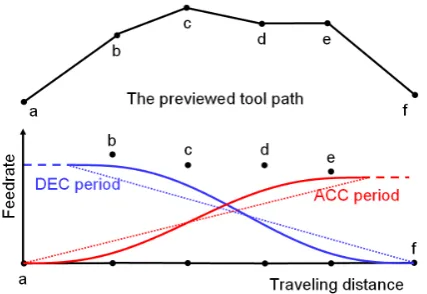
[image:2.595.323.534.52.192.2]For a given tool path with the limitations on feedrate, acceleration, and jerk, using the look-ahead scheme can complete the planning of feedrate profiles with S-curve ACC/DEC. However, care must be taken when an acceleration (or deceleration) period covers several NC blocks. As shown in Fig. 1, the feedrates along the S-curve ACC/DEC must be lower than the corresponding corner feedrates in order to make the motions with limited conditions such as the allowable over-cut distance, the limited value of acceleration, and the limited value of jerk.
Fig. 1. The feedrate profile with S-curve ACC/DEC period covers several NC blocks.
As shown in Fig. 2, suppose PBi and PBi+1 are the
adjacent cutter locations extracted from the NC block i; Fj is the sampled feedrate at the jth interpolation period by referring to the planned feedrate function F(t); T denotes the sampling time. Thus,
) ( )
(t F j T
F
Fj = t=j⋅T = ⋅ .
Because Fj denotes the feedrate at the jth interpolation period, the moving distance at the jth interpolation period,
j L
∆ , can be obtained as
T F Lj= j⋅
∆ ,
and the moving distances of motion axes can be obtained as (1). j i i i i j i j i j i L PB PB PB PB Z Y X ∆ − − = ∆ ∆ ∆ + + 1 1 (1)
Here, ∆Xij, j i Y
[image:2.595.63.277.311.458.2]∆ , and ∆Zij are the moving distances of motion axes—X-axis, Y-axis, and Z-axis—at the jth interpolation period in the NC block i; ⋅ denotes the Euclidean norm.
Fig. 2. The interpolation in a single NC block.
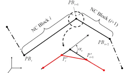
Although the interpolation method mentioned makes the cutter move with desired feedrate command, an important issue must be carefully considered for the interpolation period near the connected point of adjacent NC blocks. Consider the interpolation near the connected point of adjacent NC blocks as shown in Fig. 3. Here, Pie denotes the location of the cutter at the last interpolation of the NC block i; s
i
P+1 denotes the location of the cutter at the first interpolation of the NC block (i+1) . Define vectors as follows:
e i i c PB P A = +1−
r
; = +1− i+1
s i c P PB B
v
; e
i s i c P P
L = −
∆ +1
r
. c
α denotes the angle between (PBi+1−PBi) and )
(PBi+2−PBi+1 . Here, s i
P+1 must be determined during
interpolation; moreover, T
F Lc = c⋅ ∆
r
,
where, Fc is the feedrate command at the connected point. Therefore,
c c c A B
L v r r + = ∆ (2) and 2 2 2 )) sin( ( ) ) cos(
( c c c c c
c B A B
L α v α
r v r + + =
∆ . (3)
In other words,
(
2 cos( ))
2 2 02 = − ∆ +
+ c c c c c
c A B A L
B r r v r v α (4) and
(
) (
)
2 4 ) cos( 2 ) cos(2 2 2 2
− ∆ − ± − = c c c c c c c L A A A B r r r r
v α α . (5)
Proposition 1:
(
)
− ∆> 2 2
2
4 ) cos(
2Ac c Ac Lc
r r r α Proof: Because c c A L r r >
∆ , 1 sin2( )
c c c A L α ≥ > ∆ r r ,
and sin2( )
2 c c c A L α > ∆ r r .
Therefore,
(
1 cos2( ))
2 c c c A L α − > ∆ r r ,
and
(
)
22 2( ) 1
In other words, 2 2 2( ) 1
cos c c c A L r r ∆ − > α
and 2
2 2 4 4 1 ) ( cos c c c A L r r ⋅ ∆ ⋅ − > α .
Thus, 2 2 2 2
4 4
) ( cos
4 Ac c Ac Lc
r r r ∆ ⋅ − ⋅ > ⋅ α
and
(
2⋅ Ac cos( c))
2>4 Ac 2− ∆Lc 2 r rr
α .
Q.E.D. Therefore, according to the proposition 1,
(
)
∆ −− 2 2
2
4 ) cos(
2 Ac c Ac Lc
r r
r
α is positive and real,
and the solution of Bc v
must be (6).
− ± −
= cos( ) 2 sin2( )
2 c c c c c c A L A
B α ∆r α
r r
v
(6)
Proposition 2:
The angle αc within the range [0,π) separates the value of
− ∆ ±
−cos( ) 2 sin2( )
2 c c c c A L α α r r
into one positive value and
one negative value simultaneously. Proof:
Since 2 1
2 > ∆ c c A L r r
, 2 sin2( )
(
1 sin2( ))
2 c c c c A L α α > −
− ∆ r r ,
and sin2( )
(
cos2( ))
2 2 c c c c A L α α > − ∆ r r .
Thus, sin2( ) cos( )
2 2 c c c c A L α α > − ∆ r r
and sin2( ) cos( )
2 2 c c c c A L α α <− − ∆ − r r . Furthermore, 0 ) cos( ) cos( ) ( sin ) cos( 2 2 2 ≥ + − > − +
− c c c
c c c A L α α α ∆ α r r , and 0 ) cos( ) cos( ) ( sin ) cos( 2 2 2 ≤ − − < − −
− c c c
c c c A L α α α ∆ α r r
for αc∈[0,π).
The angle αc within the range [0,π) separates the value of
− ∆ ±
−cos( ) 2 sin2( )
2 c c c c A L α α r r
into one positive value and
one negative value simultaneously.
Q.E.D. c
Bv must be (7).
− ∆ + −
= cos( ) sin2( )
2 2 c c c c c c A L A
B α r α
r r
v
for αc∈[0,π). (7) Accordingly, ∆ ∆ ∆ = − − ⋅ + − − ⋅ = + = ∆ + + + + + + c c c i i i i c i i i i c c c c Z Y X PB PB PB PB B PB PB PB PB A B A L 1 2 1 2 1 1 v r v r r (8)
[image:3.595.315.533.265.393.2]where, ∆Xc, ∆Yc, and ∆Zc are the moving distances of motion axes, X-axis, Y-axis, and Z-axis, at the connected point of the NC block i and the NC block (i+1).
Fig. 3. The interpolation at the connected point of two adjacent NC blocks.
III. EXPERIMENTAL RESULTS
Experiments were conducted on a three-axis CNC milling machine comprising of an industrial PC, a digital signal processor (DSP)-based motion control card, and a mechanical system equipped with commercial servomotor packs. Fig. 4 shows a photograph of the experimental setup. The industrial PC possesses a Pentium IV 2.8 GHz CPU, and is used to provide functions and includes an interface for simulations, human and machine operations, implementation of the proposed approaches, and recording data values during experiments. The DSP-based motion control card contains a high-performance TI TMS320F2812 DSP, and is used as the interface for sending motion commands to and receiving feedback signals from the servomotor packs with a sampling period of 1.0 ms. The mechanical system of the milling machine is mainly composed of a vertical axis and a biaxial moving table. The biaxial moving table is driven by two AC servomotor packs equipped with built-in velocity control loop. Some motion conditions are further applied to the motion tests in order to constrain the motions of the cutting tool including:
The normal feedrate: 800 mm/min
Fig. 4. Experimental setup.
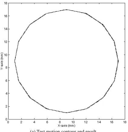
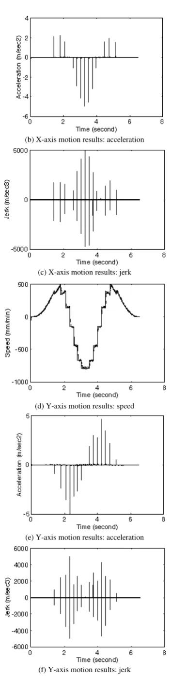
Fig. 5 shows the motion results for the segmented circular contour employed in this study; here, the segmented circular contour was applied to validate the proposed approaches because it provides uniform distribution of corner angles for the merit of verification. The acceleration and deceleration periods respectively span over several motion segments. Because of the smaller corner feedrate, the interpolated path has smaller undercut at all corners; however, the servo-lags in the applied axial servomechanisms still significantly affect the actual path. The feed motion results in Fig. 5 clearly show that the actual feedrate with values close to 800 mm/min results in the maximum value of feed acceleration of less than 0.15 m/sec2 and the maximum value of feed jerk of less than 20 m/sec3. The motion results are all varied within corresponding constraint values. Fig. 6 shows the corresponding axial kinematic profiles of the motion test. Because of the discontinuities of the motion segments at corners, the axial acceleration and axial jerk fluctuate significantly; however, all of the axial kinematic values, including axial speed, axial acceleration, and axial jerk, retain the corresponding limit values. Therefore, the motion test validates that the proposed interpolation method can generate positional motion commands in S-curve ACC/DEC periods with proper corner feedrates so as to achieve smooth motions of a cutting tool in the applications of CNC machine tools.
[image:4.595.61.278.49.196.2] [image:4.595.64.276.524.743.2](a) Test motion contour and result
Fig. 5. Test path and the corresponding feed motion results. (cont’d)
(b) Feed motion results: the planning of feedrate profiles
(c) Feed motion results: actual feedrate
(d) Feed motion results: feed acceleration
[image:4.595.344.512.617.745.2](e) Feed motion results: feed jerk
Fig. 5. Test path and the corresponding feed motion results.
(a) X-axis motion results: speed
(b) X-axis motion results: acceleration
(c) X-axis motion results: jerk
(d) Y-axis motion results: speed
(e) Y-axis motion results: acceleration
[image:5.595.81.258.37.734.2](f) Y-axis motion results: jerk
Fig. 6. Corresponding axial kinematic profiles of the motion test.
IV. CONCLUSION
Development of an interpolation method with suitable
ACC/DEC characteristics is important for high-speed CNC machining because it provides smooth feed motions for cutting tools and, thus, can shorten the machining time, maintain the machining quality, and enhance the tool life. Generally, existing methods are based on the required machining accuracy and the physical constraints of machine tools; furthermore, different ACC/DEC algorithms can generate feed motions with different acceleration and jerk characteristics. Unlike existing approaches that consider the cornering ACC/DEC at the conjunction of adjacent machining segments and the ACC/DEC periods at the beginning and ending of a single numerical control block, this study developed an interpolation method that considers an ACC/DEC period spanning over several NC blocks so that a cutting tool moving along multiple NC blocks with piece-wise continued tool paths in an S-curve ACC/DEC period can satisfy kinematic constraints with the allowable over-cut distance, the limited value of acceleration, and the limited value of jerk.
In the proposed interpolation method, the proper feedrates at the conjunctions of adjacent machining segments were applied to implement the proposed interpolation method so that the cutting tool can smoothly move and pass conjunctions with limited over-cutting values and limited feed acceleration and feed jerk values during the S-curve ACC/DEC period spinning over multiple NC blocks. Several experiments carried out on a three-axis CNC milling machine demonstrate the feasibility of the approaches proposed in this study for the applications of smooth motions when CNC machine tools execute an ACC/DEC period with multiple NC blocks.
REFERENCES
[1] J. Butler and M. Tomizuka, "Trajectory planning for high speed multiple axis contouring systems," in Proceedings of the 1989 American Control Conference, 1989, pp. 87-94.
[2] K. Erkorkmaz and Y. Altintas, "High speed CNC system design. Part I: Jerk limited trajectory generation and quintic spline interpolation,"
International Journal of Machine Tools and Manufacture, vol. 41, no. 9, pp. 1323-1345, 2001.
[3] C. W. Cheng and M. C. Tsai, "Real-time variable feed rate NURBS curve interpolator for cnc machining," International Journal of Advanced Manufacturing Technology, vol. 23, no. 11-12, pp. 865-873, 2004.
[4] M. C. Tsai, M. Y. Cheng, K. F. Lin, and N. C. Tsai, "On acceleration/deceleration before interpolation for CNC motion control," in Proceedings of the 2005 IEEE International Conference on Mechatronics, ICM '05, 2005, pp. 382-387.
[5] H. Yau, J. Wang, C. Hsu, and C. Yeh, "PC-based Controller with Real-time Look-ahead NURBS Interpolator," Computer-Aided Design and Applications, vol. 4, no. 1-4, pp. 331-340, 2007.
[6] H. B. Leng, Y. J. Wu, and X. H. Pan, "Research on cubic polynomial acceleration and deceleration control model for high speed NC machining," Journal of Zhejiang University: Science A, vol. 9, no. 3, pp. 358-365, 2008.
[7] J. W. Jeon, "Efficient acceleration and deceleration technique for short distance movement in industrial robots and CNC machine tools,"
Electronics Letters, vol. 36, no. 8, pp. 766-768, 2000.
[8] J. W. Jeon and Y. Y. Ha, "A generalized approach for the acceleration and deceleration of industrial robots and CNC machine tools," IEEE Transactions on Industrial Electronics, vol. 47, no. 1, pp. 133-139, 2000.
[9] J. Cui and Z. Y. Chu, "An improved approach for the acceleration and deceleration of industrial robots and CNC machine tools," in
Proceedings of the IEEE International Conference on Industrial Technology, 2005, pp. 1269-1273.
profile generation for industrial robotics and CNC machinery,"
Mechatronics, vol. 17, no. 9, pp. 511-523, 2007.
[11] C. S. Chen and A. C. Lee, "Design of acceleration/deceleration profiles in motion control based on digital FIR filters," International Journal of Machine Tools and Manufacture, vol. 38, no. 7, pp. 799-825, 1998. [12] F. Song, S. Hao, M. Hao, and Z. Yang, "Research on acceleration and
deceleration control algorithm of NC instruction interpretations with high-order smooth," in Lecture Notes in Computer Science (including subseries Lecture Notes in Artificial Intelligence and Lecture Notes in Bioinformatics) vol. 5315 LNAI, ed, 2008, pp. 548-557.
[13] N. Tounsi, T. Bailey, and M. A. Elbestawi, "Identification of acceleration deceleration profile of feed drive systems in CNC machines," International Journal of Machine Tools and Manufacture, vol. 43, no. 5, pp. 441-451, 2003.
[14] S. Zarifmansour and R. Seethaler, "Considering machining tolerances in high speed corner tracking," in Proceedings of the ASME Design Engineering Technical Conference, 2015.
[15] T. C. Lu and S. L. Chen, "Genetic algorithm-based S-curve acceleration and deceleration for five-axis machine tools,"
International Journal of Advanced Manufacturing Technology, pp. 1-14, 2016.
[16] Q. Zhang, X. S. Gao, H. B. Li, and M. Y. Zhao, "Minimum time corner transition algorithm with confined feedrate and axial acceleration for nc machining along linear tool path," International Journal of Advanced Manufacturing Technology, vol. 89, no. 1-4, pp. 941-956, 2017.
[17] S. Tajima and B. Sencer, "Global tool-path smoothing for CNC machine tools with uninterrupted acceleration," International Journal of Machine Tools and Manufacture, vol. 121, pp. 81-95, 2017. [18] J. H. Chen, S. S. Yeh, and J. T. Sun, "An S-curve