YD-702D-6639D
Product Specifications
3.5 FLOPPY DISK DRIVE
25.4 mm HEIGHT
Revisions
Month/ Year Revision Reason for Revision Revised Pages
Oct, 2002 Rev. A 1st edition
This product specification describes the YD-702D series double-sided, 3.5 floppy disk drive for portable applications.
(1)
In this manual, the term “drive” refers to the YD-702D series double-sided, 3.5 floppy disk drive. The term “disk” refers to the 3.5 floppy disk.*This specification may be revised without prior notice.
Make sure to check the revision number when placing an order. *Unauthorized duplication of this document is prohibited.
For the usage of this product for High Safety use
This product is assumed for general uses, such as an object for general office work, personal and home use, and is not designed or manufactured supposing for High safety use. Make sure not to use this product without taking measures to ensure the safety required for the high safety use.
High Safety Use means the use that requires extremely high security (see examples), and that accompanies a serious danger for the life and body directly, if security cannot be ensured.
Chapter 1. Introduction
The YD-702D-6639D series has been designed for 3.5 (90mm) floppy disk.
1. Full Read/ Write Compatibility
The YD-702D series provides total read/ write compatibility in both ISO standard 2.0MB (high density 2HD) and 1.0MB(double density 2DD) modes of operation.
2. Supports Three Capacity Modes
The YD-702D series provides for three capacity modes (2.0/1.6/1.0MB) to meet the requirements of worldwide standards. The drive provides full read/write compatibility across the 2.0/1.6/1.0MB standard capacities for the international market.
3. High Reliability
To guarantee high reliability, the YD-702D-6639D series employs a double-boxed structure so as to increase stiffness and decrease mounting strain caused by improper installation in a host system. A lead screw stepping motor actuator and new excitation control sequence insure highly accurate heads positioning. In addition, a brushless direct drive motor is used for accuracy and stability in rotational speed.
4. Operation in a Variety of Environments
By equipping the YD-702D series drive with a lead screw head actuator, we have been able to greatly improve resistance to shock and vibration, thereby protecting the magnetic heads and media from the effects of adverse environmental conditions.
5. A Drive for Any Need
Chapter 2. Product Specifications 2.1 Performance
Item 2.0MB Mode 1.6MB Mode 1.0MB Mode
Capacity z Unformatted z Formatted 1)Sectors/Track 2)Sectors/Track 3)Sectors/Track Recording Density Track Density Cylinders Tracks Encoding Method Rotational Speed Transfer Rate Latency(Average) Access Time z Average
z Track to Track
z Settling Time
z Turn Around Time Motor Start Time
[image:4.595.57.546.59.301.2]2.0Mbytes 18: 1474.6kBytes 17434 BPI 135 TPI 80 Cylinders 160 Tracks MFM 300 RPM 500 kbps 100 ms 94 ms 3 ms 15 ms 4 ms 0.5sec 1.6Mbytes 26: 1025.0kBytes 15: 1182.7kBytes 8: 1261.6kBytes 14184 BPI 135 TPI 77 Cylinders 154 Tracks MFM 360 RPM 500 kbps 83 ms 91 ms 3 ms 15 ms 4 ms 0.5 ms 1.0Mbytes 16: 655.4kBytes 9: 737.3kBytes 5: 819.2kBytes 8717 BPI 135 TPI 80 Cylinders 160 Tracks MFM 300 RPM 250 kbps 100 ms 94 ms 3 ms 15 ms 4 ms 0.5sec Table 2.1 Performance
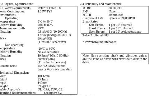
2.2 Physical Specifications 2.3 Reliability and Maintenance
DC Power Requirements Power Consumption Environment
z Operating
Temperature Relative Humidity Maximum Wet Bulb Vibration
Refer to Table 3.8 1.25W TYP
5°C to 50°C 20% to 80% 29°C
9.8m/s2{1G}(10-200Hz)
MTBF PM* MTTR
Component Life Error Rates
z Soft Errors
z Hard Errors
z Seek Errors
30,000POH None 30 minutes
5years or 20,000POH
1 per 109 bits read
1 per 1012 bits read
1 per 106 seek operations
Shock
z Non operating Temperature Relative Humidity
4.9m/s2{0.5G}(200-500Hz)
49m/s2{5G}
(11ms half-sine wave)
-20°C to 60°C No condensation
Table 2.3 Reliability
* Preventive maintenance
Vibration
Shock 19.6m/s
2{2G}(10-500Hz)
686m/s2{70G}
(11ms half-sine wave)
Note: Non-operating shock and vibration values are the same as above with or without disk in the drive. Acoustic noise Mechanical Dimensions Width Height Depth Weight Safety Approvals 45dB(A)MAX(500mm) 3ms or 6ms seek operation
101.6mm 25.4mm 149mm 390g(TYP)
UL, CSA, TÜV, CE Mounting Recommendations See figure 5.2
[image:4.595.64.546.352.661.2]Chapter 3. Interface
The interface consists of two parts: Signal and Power. Refer to figure 3.6 for all interface connections.
3.1 Interface Signals
3.1.1 Input signals
The YD-702D has input lines as shown below. All lines are active (true) when “Low”
(1) (2) (3) (4) (5) (6) (7) (8)
DRIVE SELECT 0 and 1 MOTOR ON
DIRECTION SELECT STEP
WRITE DATA WRITE GATE SIDE ONE SELECT MODE SELECT Table 3.1 Input Signals
3.1.1.1 DRIVE SELECT 0 and 1
Two drives can be daisy chained by setting the shorting plugs on the PWB. By setting “DRIVE SELECT 0” to “Low” level, the user can select the drive set at DS0. The other drive in the chain can be selected in the same way. When “DRIVE SELECT” is “Low”, the in use lamp will light and all input/ output signals except “MOTOR ON” will become valid.
If you wish to connect drives to IBM PC/AT or compatible system, please refer to “3.1.3.1 Daisy Chain Connection”.
3.1.1.2 MOTOR ON
When “MOTOR ON” is “Low” and a disk is inserted into the drive, the spindle motor will start. The spindle motor operates regardless of “DRIVE SELECT”. However if the disk is removed, the spindle motor will immediately stop.
3.1.1.3 DIRECTION SELECT
This line determines the direction of read/ write heads movement when the “STEP” line is pulsed.
“HIGH” level Out(away from the center of the disk) “LOW” level In(toward the center of the disk) Table.3.2. DIRECTION SELECT
Any change on this line must be done at least 1 usec. before the leading edge of the step pulse, and at least 1 usec. after the trailing edge of the step pulse. Refer to figure 3.9 for timing.
3.1.1.4 STEP
This signal moves the read/ write heads in the direction defined by the “DIRECTION SELECT” signal.
The access motion is initiated on each “Low” to “High” level transition, in other words, with the trailing edge of the signal pulse. In a seek operation, an 18 ms delay following the last “STEP” pulse is required for settling time before any read/ write operation can be initiated. After completing seek operation, minimum 4 ms delay is required before initiating the next seek operation.
Please do not change the interval of step pulse during seek operation. It will be cause of seek error.
Refer to figure 3.10 for timing.
3.1.1.5 WRITE DATA
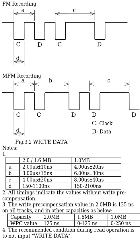
The “WRITE DATA” line provides the data to be written on the disk. Each transition from “High” to “Low” on the line causes the current through the read/ write heads to be reversed, thereby writing a data bit. This line is enabled when the “WRITE GATE” line is “Low” active. Refer to figures 3.2 and 3.12 for the timing
information.
FM Recording
MFM Recording
Fig.3.2 WRITE DATA Notes:
1.
2.0 / 1.6 MB 1.0MB
a 2.00us±10ns 4.00us±20ns
b 3.00us±15ns 6.00us±30ns
c 4.00us±20ns 8.00us±40ns
d 150-1100ns 150-2100ns
2. All timings indicate the values without write pre-compensation.
3. The write precompensation value in 2.0MB is 125 ns on all tracks, and in other capacities as below:
Capacity 2.0MB 1.6MB 1.0MB
WPC value 125 ns 0-125 ns 0-250 ns
4. The recommended condition during read operation is to not input “WRITE DATA”.
3.1.1.6 WRITE GATE
[image:5.595.315.559.134.552.2]A “Low” active level on this line allows “WRITE DATA” to be written on the disk. A “High” inactive level enables read data logic and stepping logic. Refer to figure 3.12 for the timing information. Activation of “DRIVE SELECT” and “MOTOR ON”, changing
“SIDE ONE SELECT” and/ or activation of “STEP” must be delayed at least the values indicated (see the following READ RECOVERY TIME table 3.3) following deactivation of “WRITE GATE” because the erase heads remain active during this period.
Capacity 2.0MB 1.6MB 1.0MB
RRT MIN 650 us 590us 1000 us
Table 3.3 Read Recovery Time
C
D
C
D
d
c
a
C
C
D
D
D
c
a
b
d
C:
D:
ClockData3msMIN
3.1.1.7 SIDE ONE SELECT
This line defines which side of a two sided disk will be used for reading or writing. A “High” level on this line selects the read/ write head on side 0 surface on the disk. A “Low” level on this line selects the read/ write head on the side 1 surface. When switching heads, a 100 usec. delay is required before any read or write operation can be initiated.
3.1.1.8 MODE SELECT
The YD-702D series has an internal circuit that performs the switching of the drive’s three (2.0/1.6/1.0MB) capacity modes on using various ways, depending on the individual model purchased. The switching is carried out as described in table 3.4 according to the setting of the shorting plug on the drive’s PWB. YD-702D-6639D drive are shipped with shorting plugs in the standard setting. Please refer to below and table 6.1 .
Short Plug
Setting CapacityMode SwitchingMethod Specifications IF-OPEN
T2-OPEN 2 Mode(2.0/1.0MB) AutomaticSwitching Automatic switching is performed according to the media type in thedrive. The drive is in 2.0MB mode with high density media (2HD) and in 1.0MB mode with double density media (2DD).
IF-SHORT
T2-OPEN 3 Mode(2.0/1.6/1.0MB) AutomaticSwitching with Interface Signal
The drive is in 1.0MB mode with double density media and independent of the “MODE SELECT” signal (J1-2).
If high density media is inserted with the “MODE SELECT” signal is “LOW” when the drive is in 1.6MB mode.
If high density media is inserted with the “MODE SELECT” signal is “HIGH” when the drive is in 2.0MB mode.
IF-SHORT
T2-SHORT 3 Mode(2.0/1.6/1.0MB) AutomaticSwitching with Interface Signal
The drive is in 1.0MB mode with double density media and independent of the “MODE SELECT” signal (J1-2).
If high density media is inserted with the “MODE SELECT” signal is “HIGH” when the drive is in 1.6MB mode.
If high density media is inserted with the “MODE SELECT” signal is “LOW” when the drive is in 2.0MB mode.
IF-OPEN
T2-SHORT 2 Mode(1.6/1.0MB) AutomaticSwitching Automatic switching is performed according to the media type in thedrive. The drive is in 1.6MB mode with high density media (2HD) and in 1.0MB mode with double density media (2DD).
Table 3.4 MODE SELECT
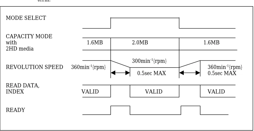
Notes: (1)To switch capacity mode is effected by a signal level on the “MODE SELECT” signal.
(2)It is necessary to wait 0.5 sec. before executing a read/write operation after motor revolutional speed is switched for capacity mode change. “READ DATA”, ”INDEX”, signals are inhibited to output during this term.
MODE SELECT
CAPACITY MODE
with 1.6MB 2.0MB 1.6MB
2HD media
300min-1{rpm}
REVOLUTION SPEED 360min-1{rpm} 360min-1{rpm}
0.5sec MAX 0.5sec MAX
READ DATA,
INDEX VALID VALID VALID
[image:6.595.50.484.512.736.2]READY
3.1.2 Output signals
Output signals are shown below. All lines are active when the “DRIVE SELECT” signal is “Low”.
(1)TRACK 00 (2)INDEX
(3)WRITE PROTECT (4)READ DATA (5)DISK CHANGE (6) READY
(7) HIGH DENSITY Table 3.5 Output Signals
3.1.2.1 TRACK 00
A “Low” active level on this line indicates that the read/ write heads are positioned at track 00(the outermost track). The line goes “High” inactive when the heads are positioned elsewhere. Refer to Fig.3.9 for the timing information.
3.1.2.2 INDEX
One index pulse is output at each revolution of the disk when the drive is ready to read/ write. Normally this signal is at “High” level, and makes the transition to “Low” level when a pulse is generated. This signal is inhibited to output during seek and not ready. The controller should detect “INDEX” with the leading edge
of the transition rather than with the signal level.
3.1.2.3 WRITE PROTECT
A “Low” active level on this line indicates that a disk with a write protect notch is loaded. During normal operation the drive will prevent writing when a protected disk has been inserted.
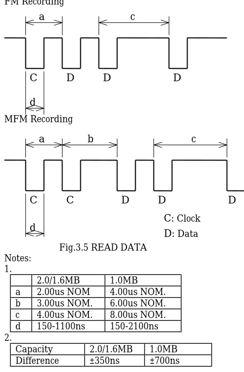
3.1.2.4 READ DATA
This line provides the “READ DATA”(clock and data together) as detected by the drive electronics. Normally this signal is “High” level and becomes “Low” level for each flux reversal.
The transition from “High” to “Low” level should be used for separation of data bits from read data. This signal is inhibited to output during seek and not ready.
The different value between the leading edge of each bit pulse and its nominal position is below note 2. Timing characteristics are shown in figure 3.11.
FM Recording
MFM Recording
Fig.3.5 READ DATA Notes:
1.
2.0/1.6MB 1.0MB
a 2.00us NOM 4.00us NOM.
b 3.00us NOM. 6.00us NOM.
c 4.00us NOM. 8.00us NOM.
d 150-1100ns 150-2100ns
2.
Capacity 2.0/1.6MB 1.0MB
Difference ±350ns ±700ns
3.1.2.5 DISK CHANGE
The “DISK CHANGE” signal indicates that the disk has been removed. This signal becomes “Low” after power has been applied to the drive and the disk has been removed. This signal remains active until the following conditions have satisfied:
(1) A disk is correctly inserted.
(2) A drive has been selected and a step pulse has been applied.
3.1.2.6 READY
This signal remains “Low” for a maximum 0.5 sec after the media is inserted and “MOTOR ON” signal is activate.
3.1.2.7 HIGH DENSITY
This signal indicates an inserted media type. This signal becomes “HIGH” when 2DD media is inserted, and “LOW” when 2HD media is inserted or no media.
C
D
D
D
d
c
a
C
C
D
D
D
c
a
b
d
C:
D:
ClockData(166.7ms± 1.5%) 200.0ms± 1.5%
[image:7.595.316.556.49.414.2]1~8ms
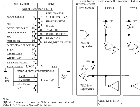
Notes:
(1)Main frame and connector fittings have been shorted. Refer to “4.1.3 Frame Ground” for details.
(2)Marking “*” on the signal name indicates an optional signal.
Please refer to “6.4 Shorting Plug Functions”.
Fig.3.6 Interface Connection
3.1.3 Interface Circuits
The YD-702D series uses open collector drivers as output line drivers, and TTL level gates as input line receivers. The input of each receiver is terminated in 1 k ohms pulled up to Vcc (+5V). Input/ output circuit electrical specifications are as shown below.
Inactive “High” Level 2.0 V to Vcc Active “Low” Level 0 to 0.8 V
Input Impedance 1 k ohms pulled up to Vcc Table 3.6 Input Circuit Electrical Specifications
Inactive “High” Level Open Active “Low” Level 0 to 0.4V
[image:8.595.46.537.57.434.2]Sink current: 40mA MAX Table 3.7 Output Circuit Electrical Specifications
The illustration below shows the recommended controller interface circuit.
3.1.3.1 Daisy Chain Connection
When using two drives connected in a daisy chain, it is inadvisable to leave any of them unpowered.
Each drive should receive power from the host system.
3.1.3.2 Host System Terminal Resistor
Because the line driver of the drive is an open collector output, please use a terminal resistor on the host system side. 7438 or Equivalent 74LS14 or Equivalent +5V 1k (150~) +5V +5V 1k 1k Drive 1 Drive 0 Host System
Cable 1.5 m MAX
Fig.3.7 Interface Circuit Drive
Host System
Signal Connector (P1/J1)
DIRECTlON SELECT DRIVE. SELECT 0* N.C.
N.C. STEP
DRlVE SELECT 1
WRITE DATA MOTOR ON
WRITE GATE SIDE ONE SELECT
DISK CHANGE* / HIGH DENSITY * HIGH DENSITY* lNDEX WRlTE PROTECT TRACK 00 READ DATA READY/DISK CHANGE*
2
N.C. Signal ReturnsPower Supply Connector (P2/J2)
+5 V DC +5 V Return +5 V Return
4
8
6
10
12
14
16
18
20
22
24
32
KEY Signal GND DCGND Frame GND
[image:8.595.303.547.67.444.2]3.1.4 Timing
3.1.4.1 Track 00 Timing
Fig.3.9 Track 00 Timing
3.1.4.2 Seek Timing
In order to reduce the peak current, we recommended that no seek operation be performed for 0.2 seconds after motor start. Figure 3.10 shows the preferred timing.
3.1.4.3 Read Timing
Note:
Capacity 2.0MB 1.6MB 1.0MB
X us MIN 650 us 590 us 1000 us
Fig.3.11 Read Timing
3.1.4.4 Write Timing
Note:
Capacity 2.0MB 1.6MB 1.0MB
X us MIN 650 us 590 us 1000 us
Y us MAX 4 us 4 us 8 us
Fig.3.12 Write Timing
DIRECTlON STEP TRACK 00
2.9ms MAX 17us MAX
MOTOR ON
ON DRlVE SELECT
DIRECTlON SELECT STEP
0.5us MIN
1us MIN 1us MIN
1us MIN
200 ms MIN
3 ms MIN 4 ms MIN
3 ms MIN
ON DRlVE SELECT MOTOR ON
STEP
SIDE ONE SELECT
READ DATA (VALID) WRITE GATE
500 ms MAX
18 ms MAX
100us MAX 100us MAX Xus MAX VALID VALID
ON DRlVE SELECT
WRITE GATE WRITE DATA MOTOR ON
STEP
SIDE ONE SELECT 500 ms MIN
18 ms MIN
Yus MAX Yus MAX 100us MIN
Xus MIN Xus MIN
Xus MIN
3.2 Power Interface
3.2.1 Power Supply Specifications
Voltage Operating Mode TYP(mA) MAX(mA)
Standby 3 5
Read 250 350
Write 250 350
+5VDC ±10%
(Ripple: 100 mVp-p MAX)
Seek 400 550
Motor Start 700 850
Peak
Seek 600 800
Table 3.8 Power Supply Specifications
Notes:
(1) “MAX” values reflect measurement taken at maximum voltage; “TYP” values reflect measurement taken at nominal voltage.
(2) “Standby” refers to the state where all input signals are inactive.
(3) “Read” and “Write” refer to the state where the heads are at track 40, side 1 and the In Use Lamp is on. (4) “Seek” refers to the average current with the drive continuously seeking at 3 ms and the spindle motor rotating. (5) When the spindle motor starts, “Motor Start” current will continue for approximately 200 ms.
(6) Peak current of “Seek” refers to the state of maximum seek current when the spindle motor is rotating and the heads are stepping at 6 ms.
The above specifications must be met when voltages are measured at power connector on PWB.
3.2.2 Current Waveform
5 V DC (TYP)
MOTOR
START
STAND
BY
STAND
BY
SEEK
READ
READ
WRlTE
[mA] 1000
800 600 400 200 0
Chapter 4. Physical Interface
The connection with the host system is made with two connectors, signal connector P1/J1 and power connector P2/J2.
Figure 4.1 shows the cable connections.
4.1 Connector and Cable
4.1.1 Signal Connector and cable(J1/P1)
4.1.1.1 Connector (J1)
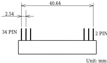
The J1 connector is a 34 pin male connector (JAE:PS-34PE-D4LT1-P1 or equivalent) located at the rear of the drive.
The row of pins closest to the PWB is the odd numbered pins.
Refer to figure 4.2 for the J1 connector dimensions.
4.1.1.2 Flat Cable Connector(P1)
P1 is a mating connector which connects J1 and the flat
cable of the host system.
Recommended connector:
JAE PS-34SEN-D4P1-1C(Closed End) JAE PS-34SEN-D4P1-1D(Daisy Chain) Cable: 3M 3365-34(1.5 m MAX)
4.1.2 DC Power Connector and Cable(J2/P2)
The J2 connector is a four pin male connector(AMP: 171826-4 or equivalent) located at the rear of the drive.
Recommended components: Receptacle(4 pin): AMP 171822-4 Contact: AMP 170204-2
Cable: AWG20
4.1.3 Frame Ground
The internal circuit ground on the PWB has been connected with the frame for shielding purposes. The frame ground of the system will be connected to the signal ground through the drive when the drive is installed into the system.
Signal cable
Host System
Drive 0
Power Cable
Drive 1
P1 J1
P2 J2
P1 J1
[image:11.595.70.302.110.273.2]P2 J2
Fig.4.1 Cable Connections
40.64
2.54
2 PIN 34 PIN
Unit: mm Fig.4.2 J1 Connector Dimensions
PWB
[image:11.595.321.553.239.376.2]2 1 4 3
[image:11.595.84.294.419.544.2]4.2 Connector Pin Assignments
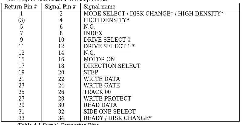
4.2.1. Signal Connector Pin Assignments Return Pin # Signal Pin # Signal name
1 (3)
5 7 9 11 13 15 17 19 21 23 25 27 29 31 33
2 4 6 8 10 12 14 16 18 20 22 24 26 28 30 32 34
MODE SELECT / DISK CHANGE* / HIGH DENSITY* HIGH DENSITY*
N.C. INDEX
DRIVE SELECT 0 DRIVE SELECT 1 * N.C.
MOTOR ON
DIRECTION SELECT STEP
WRITE DATA WRITE GATE TRACK 00
WRITE PROTECT READ DATA SIDE ONE SELECT READY / DISK CHANGE* Table 4.1 Signal Connector Pins
Note: (3) is used as a key pin.
Marking “*” on the signal name indicates an optional signal. Refer to “6.4 Shorting Plug Functions” for details.
4.2.2 DC Power Connector Pin Assignments
Pin # Name
1 2 3 4
[image:12.595.65.464.87.294.2]+5V DC +5V RETURN +5V RETURN NO CONNECTION Table 4.2 Power Supply Connector Pins
4.3 Terminators
Chapter 5. Diagrams
The color for front is as allow: Ivory (Munsell 6Y8.5/ 0.5 equivalent)
In use lamp (LED) color is green.
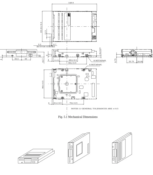
[image:13.595.47.563.160.750.2]YD-702D DIMENSIONS
Fig. 5.1 Mechanical Dimensions
Fig. 5.2 Recommended Mounting
BUTTON STROKE
60+/-0.5 90+/-0.5 30.5 30
6
16.7
149.0
101.6+/-0.3
25.4+/-0.3
5+/-0.5
4
94+/-0.5
70+/-0.5
8.75 8
6-M3TAPx6L
4-M3TAPx6L
21+/-0.5
4
31+/-0.5 4
0.7 5.2
11.5
6
20.09 35.75
5.1 Caution on Mounting
1) Mounting screws should be tightened by 0.5 ~ 0.6Nm{5 ~ 6 kgf•cm} in torque.
2) Mounting bracket is recommended not to make contact with the drive except the mounting spots, and should not be designed that any portion on the drive except the mounting spots is pressed and/ or crushed.
3) Recommended to fasten the drive at 3 mounting spots with screws (4 spots available).
4) Mounting bracket should be provided structure to absorb strain.
5) The drive should be separated or shielded from noise sources.
Do not strain the drive. Do not install the drive in large electromagnetic fields.
Otherwise, failure may result.
5.2 Caution on handling
1) Strong vibration and shock can damage the drive. It may cause an error. Do not use or store the drive under such conditions.
2) We recommend handling the drive on side frame, portion of mounting spots, of the drive as well as possible. If you handle like pressing the top or the bottom of the drive, it may cause damage of heads and PWB.
3) Do not disassemble the drive by yourself because of an adjusted product. If you do so, we can not assure you of adjusted accuracy.
Chapter 6. Other Functional Characteristics
6.1 Standby Mode
The YD-702D includes standby mode to reduce the load on the host system power supply when the drive is not actually in use. When the spindle motor stops, power to the read/ write and spindle motor control systems is cut off, and power to the stepper is cut off when the stepper is not seeking.
6.2 Mask Function
“READ DATA” and “INDEX” signals are inhibited to output during seek (includes 18 ms MAX after the last step pulse) and not ready (500 ms MAX after motor start).
6.3 Automatic Motor On/Off
When the disk is inserted or removed, the spindle motor is controlled as follows:
1) When the disk is inserted, the spindle motor will start to rotate regardless of the “MOTOR ON” signal condition. The spindle motor will stop approximately 400 ms later if the “MOTOR ON” signal is not active, but will continue to rotate if it is active.
2) When the disk is removed, the spindle motor will stop.
6.4 Shorting Plug Functions 6.4.1 Shorting Plugs Setting
YD-702D-6639D-021051
Shorting plug is mounted
Nothing
H2
DC2
DC IF RY
T2 DS0 DS1
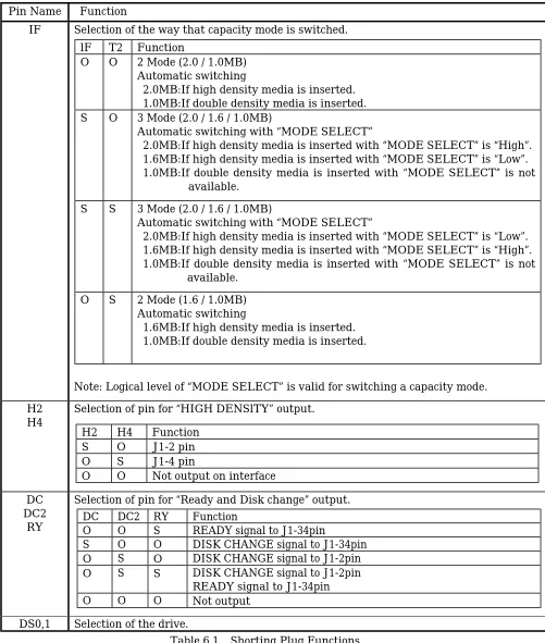
Pin Name Function
IF
Selection of the way that capacity mode is switched.
Note: Logical level of “MODE SELECT” is valid for switching a capacity mode.
H2
H4
Selection of pin for “HIGH DENSlTY” output.
DC
DC2
RY
Selection of pin for “Ready and Disk change” output.
[image:15.595.66.567.55.646.2]DS0,1
Selection of the drive.
Table 6.1 Shorting Plug Functions
Note: Shorting plugs are IRISO IMSA-9215H-T or equivalent (2mm pitch).
lF
T2
Function
O
O
2 Mode (2.0 / 1.0MB)
Automatic switching
2.0MB:If high density media is inserted.
1.0MB:If double density media is inserted.
S
O
3 Mode (2.0 / 1.6 / 1.0MB)
Automatic switching with “MODE SELECT”
2.0MB:If high density media is inserted with “MODE SELECT” is “High”.
1.6MB:If high density media is inserted with “MODE SELECT” is “Low”.
1.0MB:If double density media is inserted with “MODE SELECT” is not
available.
S
S
3 Mode (2.0 / 1.6 / 1.0MB)
Automatic switching with “MODE SELECT”
2.0MB:If high density media is inserted with “MODE SELECT” is “Low”.
1.6MB:If high density media is inserted with “MODE SELECT” is “High”.
1.0MB:If double density media is inserted with “MODE SELECT” is not
available.
O
S
2 Mode (1.6 / 1.0MB)
Automatic switching
1.6MB:If high density media is inserted.
1.0MB:If double density media is inserted.
H2
H4
Function
S
O
J1-2 pin
O
S
J1-4 pin
O
O
Not output on interface
DC
DC2
RY
Function
O
O
S
READY signal to J1-34pin
S
O
O
DISK CHANGE signal to J1-34pin
O
S
O
DISK CHANGE signal to J1-2pin
O
S
S
DISK CHANGE signal to J1-2pin