Figure 12 Microfiltration flux when filtering a particle suspen-sion, with and without backflush.
(about 0.5 bar) for several seconds every few minutes (Figure 12).
Fouling is reduced by high cross-Sow velocities and low transmembrane pressures. High cross-Sow vel-ocities cause high-pressure drops along the membrane, which cause the P to be undesirably high at the entrance of the membrane module. Therefore microR l-tration processes have been developed which facilitate a cross-Sow both on the feed side and on the permeate side. The pressure drops on both sides are similar in magnitude, guaranteeing a uniform transmembrane pressure. This method of operation has been shown to be effective in many dairy applications.
Other process techniques to reduce fouling are the use of pulsedSow, gas sparging, and electric or acous-ticRelds, and the use ofSow geometries that create secondary Sows or vortices resulting in high shear rates (e.g. the use of ‘turbulence promoters’ or curved channels).
Conclusions
Over the last 70 years, microRltration has developed from a small specialized technology used only in
laboratories to a multibillion dollar industry for separation and puriRcation of liquid and gas streams. Especially since the 1980s, exciting new applications have become possible, due to improved membranes (for example, ceramics) and improved technologies (for example, backpulsing, uniform transmembrane pressure). Still, great challenges exist, for example in the processing of beverages, such as fruit juices, milk, and beer, where membrane fouling seriously impairs the economy of the process.
To overcome these problems, researchers and en-gineers are becoming increasingly interested in hybrid and combined processes. Combining microRltration with good pre- and post-treatments or with other separation processes may result in better and more economic separations.
See also: II/Membrane Separations: Filtration.
Further Reading
Belfort G, Davis RH and Zydney AL (1994) The behavior of suspensions and macromolecular solutions in cross-Sow microRltration.Journal of Membrane Science 96: 1}58.
Bowen WR and Jenner F (1995) Theoretical descriptions of membrane Rltration of colloids and Rne particles: an assessment and review.Advances in Colloid and Inter-face Science56: 141}200.
Ho WSW and Sirkar KK (1992) Membrane Handbook. New York: Van Nostrand Reinhold.
Howell JA, Sanchez V and Field RW (1993)Membranes in Bioprocessing } Theory and application, 1st edn. London: Chapman and Hall.
Mulder M (1992)Basic Principles of Membrane Techno-logy, 1st edn. Dordrecht: Kluwer Academic Publishers. Scott K (1995) Handbook of Industrial Membranes.
Oxford: Elsevier Science.
Zeman LJ and Zydney AL (1996) MicroTltration and UltraTltration. Principles and Applications. New York: Marcel Dekker.
Pervaporation
H. E. A. BruKschke and N. P. Wynn,
Sulzer Chemtech GmbH, Neunkirchen, Germany
Copyright^ 2000 Academic Press
Development
In 1917 PA Kober published a paper in which he described his observation that ‘a liquid in a collodion
general a process in which one component out of aSuid mixture selectively permeates through a dense membrane, driven by a gradient in partial vapour pressure, leaving the membrane as a vapour, and being recovered in a condensed form as a liquid.
In the years following Kober’s publication a num-ber of papers were published describing membranes and processes for pervaporation. Especially during the 1950s, the interest focused on pervaporation membranes and processes for the separation of differ-ent classes of hydrocarbons and of isomeres and nu-merous patents were granted. Membrane materials disclosed were natural and synthetic rubbers, cellu-lose esters and ethers, and several treated and un-treated polyoleRnes. None of this early membrane, however, was used in any industrial process, owing to insufRcientSux and selectivity.
Pervaporation, vapour permeation and gas per-meation are very closely related processes. The driving force is always a gradient in partial vapour pressure, and transport through the membrane can best be described by a so-called ‘Solution-Diffusion-Mechanism’. In this mechanism it is assumed that a component of the feed having a high afRnity to the membrane is easily and preferentially absorbed and dissolved in the dense membrane. Following a con-centration gradient it migrates through the membrane by a diffusion process and is desorbed at the down-stream side of the membrane. The separation charac-teristic of the membrane is thus governed primarily by the solubility of components in the membrane material and, to a lesser extent, by its diffusivity which even may counteract against the solubility sep-aration.
In pervaporation and vapour permeation processes the partial vapour pressures of the components at the feed side areRxed by composition and temperature of the feed; they can be inSuenced only by increasing the temperature. Therefore, the driving force for the transport of matter through the membrane is applied by reducing the partial vapour pressure at the per-meate side.
Different means have been proposed in order to effect this reduction of the permeate side partial va-pour pressure:
E The permeate side of the membrane is swept with an inert gas in which the partial vapour pressure of the critical (preferential permeating) component is kept sufRciently low. If the gas stream cannot be wasted it has to be reconditioned and recycled. E All permeating vapour is removed by means of
a vacuum pump. The vapour may be condensed after recompression at the downstream side of the pump.
E The permeated vapour is condensed at sufRciently low temperatures. As the condenser surface will be installed at a certain distance to the permeate side of the membrane all non-condensable gases have to be removed from the permeate compartment in order to minimize permeate side pressure losses.
In most industrial installations the last has been proven to be the most effective and economical pro-cess.
In a pervaporation process the feed is applied as a liquid and all partial vapour pressures of the com-ponents in the feed mixture are at saturation level. Within the limits of membrane stability and process requirements, temperature and pressure on the feed side are free adjustable parameters.
In vapour permeation a vaporous feed mixture is applied, with at least the partial vapour pressure of the preferential permeating component at or close to saturation conditions. Temperature and pressure of the feed are linked by vapour}liquid equilibrium and can be chosen within these limits only.
In gas permeation all partial vapour pressures at the feed side are below saturation and the permeate can no longer be condensed. By increasing the total feed side pressure the driving force for the transmem-brane transport can be adjusted.
Pervaporation treatment liquid feed mixtures is in-sofar unique compared with other membrane pro-cesses as the transport of matter across the membrane is coupled with a phase change from liquid to vapour. The heat of evaporation is extracted from the liquid feed and transported through the membrane, too. As a consequence the temperature of the feed is reduced, which reduces driving force and transmembrane Sux. Different means such as heated modules have been proposed to replace the lost heat of evaporation. In general, the total membrane area is split into a number of segments (stages) arranged in series with intermediate heat exchangers between each two seg-ments or stages.
Membranes and Modules
Membranes
evaporation of the permeate vapour is lost a single step membrane process saves energy compared with, e.g., distillation.
Two different types of pervaporation membranes were developed at about the same time in the begin-ning of the 1980s:
E Hydrophilic membranes, with a preferential per-meation for water, used mainly for the removal of water from organic solvents and solvent mixtures, with an emphasis on azeotropic mixtures.
E Organophilic membranes for the removal of volatile organic components from water and gas streams.
In both applications composite membranes are used, allowing for very thin separation layers but with sufRcient chemical, mechanical and thermal stability. Because the composite structureSat sheet conR gura-tions are preferred. The substructure of both types of pervaporation membranes is very similar: a porous support membrane with an asymmetric pore struc-ture is laid onto a carrier layer of a woven or non-woven textile fabric and a basic ultraRltration mem-brane is formed. On the free side of this porous substructure the pores have diameters in the order of 20}50 nm which widen up to the fabric side to the micrometre range. Polyester, polypropylene and sim-ilar Rbres are used for the textile carrier layer; structural polymers such as polyacrylonitrile, polyetherimide, polysulfone, polyethersulfone and polyvinylidenSuoride form the porous support.
On this substructure a thin dense layer (in the range of 0.5}5m thick) is coated, which effects the separ-ation. Different coating techniques are in use, most commonly a solution of the respective polymer in an appropriate solvent is spread onto the porous sub-structure. The solvent is then evaporated, followed by further treatment to effect cross-linking of the polymer.
In hydrophilic membranes the separating layer is made from cross-linked polyvinyl alcohol (PVA), from polyimides, or natural polymers such as chitosan or cellulose acetate (CA), with PVA domi-nant. For organophilic membranes, the separation layer is formed mostly from siloxanes such as polydimethylsiloxane (PDMS), or polyoctylmethyl siloxane (POMS).
In recent years new efforts have been made in academia and industry to develop new membranes for organic}organic separation. Of speciRc interest are the separation of oleRns from parafRns, e.g. propene from propane, aromatics such as benzene or toluene from aliphatic hydrocarbons or the separ-ation of the xylene isomers. To date, no industrial-ization has been achieved. The only industrial
processes in this area are the separation of the light alcohols methanol and ethanol from their mixtures with hydrocarbons, ethers and esters. The mem-branes in use are, however, more of the hydrophilic type, in which the more polar alcohols replace the water.
To date, only polymeric membranes have been applied in pervaporation and vapour permeation pro-cesses. Thermal, mechanical and chemical stability of the porous substructure are limiting the operation range of this type of membrane, more than the stabil-ity of the separating layer. Demand for higher opera-tion temperatures and chemical resistance have stimulated the development of inorganic substruc-tures, and porous ceramics in particular. These can be coated by cross-linked polymeric separating layers similar to those on polymeric substructures. In more recent developments organic separation layers are applied, either by coating the porous substructure with a layer of zeolites or by reducing the size of the pore to molecular dimensions. The separation mech-anism of these membranes is even more complex than that of polymeric separating layers, as molecular siev-ing effects, caused by shape and size of mol-ecules, and molecule}surface interaction decide whether a component can pass through the mem-brane or will be retained.
Modules
Design of modules for pervaporation and vapour permeation processes was based on the experience gained in water treatment by membranes, such as ultraRltration and reverse osmosis processes. How-ever, signiRcant modiRcations had to be made be-cause of the speciRc requirements of pervaporation and vapour permeation processes.
The partial vapour pressure at the permeate side has to be reduced in both processes to fairly low values, especially when lowRnal concentrations have to be reached in the retentate. Therefore any pressure losses, even in the range of a few millibars have to be avoided at the permeate side. Since any feed mixture will contain organic components at high concentration, mostly at elevated temperatures, the chemical stability of all module components, such as spacer and potting material and glues is criti-cal. To date, two types of modules are most widely applied:
Figure 1 Vapour}liquid equilibrium curves for common phar-maceutical solvents which azeotrope with water. All can be dehy-drated using pervaporation.
Table 1 Solvents routinely dehydrated using pervaporation/ vapour permeation
Isopropanol, ethanol
Standard applications for pervaporation, typ-ically dehydrated from their azeotropes to fractions of a percent of water. Many continu-ous, batch and vapour permeation units are operating around the world.
Ethyl acetate, butyl acetate
Form azeotropes in the miscibility gap and were traditionally dehydrated by two distillation columns and a phase separator, however with a massive recycle. Esters de-compose in contact with zeolites. Pervapora-tion/vapour permeation is easily the best technique for dehydration.
Acetone Does not azeotrope with water but when dis-tilled a large reflux is required to get a half dry product. Pervaporation is ideal for final dehy-dration or for debottlenecking existing distil-lation systems.
Tetrahydrofuran Easily dehydrated by pervaporation down to a few hundred ppm water. Traditional caustic washing is operationally messy, requiring a redistillation of the product. Pressure swing distillation requires high pressures and large recycles.
Methyl ethyl ketone
Pervaporation is again the preferred tech-nique. Distillation is only possible with an entrainer because the azeotropic composi-tion is nearly identical to the miscibility limit. N-butanol,
n-propanol
Form azeotropes with high water content so the distillation/phase separation process in-volves massive recycle streams. Pervapora-tion plants are less costly to build and easier to operate.
are assembled inside a special vacuum vessel that also house the permeate condenser. Alternative de-signs are very similar to plate heat exchangers, in which the supported membrane replace the heat exchanger plates. These modules are closed to the outside, with internal ducts feed and retentate, and for permeate removal.
E Spiral wound modules with stainless steel central tubes, but otherwise similar to those known from the conventional membrane processes, are mainly used for organophilic membranes. One or several of the spiral wound modules are housed inside a pressure tube and assembled in conventional skids. In a special design, the sandwich structures of membranes and permeate and feed spacer are welded together and not spirally wrapped around the central tube but arranged asSat sheets on the central tube for the removal of the permeate.
Very rarely, hollowRbres are used, generally with the feedSow inside the bore of the Rbre. For the more conventional arrangement}feedSow at the shell side of theRbre}permeate pressure losses inside the bore may become detrimental for the process.
Applications
Organophilic Membranes
Organophilic membranes are mostly applied for the removal of volatile organic components (VOCs) from a gas stream such as waste air or nitrogen. The main applications are the treatment of streams originating from the evaporation of solvents in coating processes inRlm and tape production, purging of products such as polymers, by which unreacted monomers are re-moved, or from breathing of storage tanks for
sol-vents, especially from loading and unloading of petrol tanks in tank farms. In many installations the feed stream received at atmospheric pressure is com-pressed in order to increase the feed side partial va-pour pressure. Partial condensation of the component to be removed is a wanted side effect, since then condensation on the permeate side under vacuum and at low temperature can be avoided. The permeate is simply slightly compressed by the vacuum pump and let into the inlet of the feed compressor. In speciRc cases the installation of a vacuum pump will not be necessary and the permeate is obtained at atmos-pheric pressure.
The economy of the process is usually determined by the value of the components recovered. Emission regulations in all industrial countries demand for very lowRnal concentrations if the gas stream is released to the atmosphere, therefore the retentate from the gas puriRcation by the membrane is either recycled or followed by an additional polishing step.
[image:4.568.289.519.359.706.2]Figure 2 Typical flow diagram for recovery of solvent from mother liquors.
Figure 3 (See Colour Plate 51). Vapour permeation unit for recovering ink solvent.
VOCs from aqueous stream, this technique has not yet been introduced into the industry. Potential mix-tures which could be treated are more complex, the economical value of the recovered substances are low, and competing processes such as biological treatment of wastewater are cheaper. Applications may be found in the future in biotechnological processes where high-value products can be separated from a fermentation broth and be concentrated and puri-Red in the same step.
Hydrophilic Membranes
The largest industrial installations of pervaporation and vapour permeation processes are equipped with hydrophilic membranes which are used for the re-moval of water from organic solvents and solvent mixtures.
Solvent dehydration Organic solvents are used for a variety of purposes in the chemical industry, e.g. for synthesis of pharmaceuticals, to precipitate materials from aqueous solutions, for cleaning purposes and for drying Rnal products. Spent solvents nearly always contain some water. Dehydration is therefore an essential step in their recovery but difRcult since most solvents from azeotropes with water. Final water removal by distillation is then impossible or complic-ated. Entrainer use is not an option for pharmaceut-ical orRne chemical production, where stringent pro-cess certiRcation rules out adding potential sources of contamination.
Pervaporation enables solvents to be dehydrated without using any third substance or entrainer, sim-ply, cheaply and without problems and irrespective of vapour/liquid equilibria (Figure 1). On-site solvent recovery using pervaporation and vapour permeation is thus becoming standard practice in the pharma-ceutical and chemical industries (Table 1).
Often, pervaporation and vapour permeation plants are designed for operation with a number of solvents and with mixtures of solvents. Pervaporation and vapour permeation offers the following bene-Rts when dehydrating solvents:
[image:5.568.72.263.399.688.2]Figure 4 Carbon bed adsorption using steam regeneration and vapour permeation for final solvent dehydration.
Figure 5 Use of vapour permeation to recover solvent from
nitrogen desorption circuit. Figure 6 Vapour}liquid equilibrium diagram for acetone}water. E A choice of batch or continuous pervaporation
systems, or continuous vapour permeation, de-pending on the duty.
E Able to dehydrate esters without any decomposi-tion.
E Low energy consumption.
Solvent recovery from mother liquors Spent sol-vents (mother liquors) typically contain some water and are often saturated with dissolved material. They cannot be re-used without puriRcation. Evaporation combined with vapour permeation is a powerful tech-nique for purifying and dehydrating mother liquors (Figure 2).
The feed of spent solvent is evaporated and the resulting vapour is fed directly to a vapour per-meation unit. Water vapour selectivity permeates the membrane and is condensed under vacuum. The water-free solvent vapour leaving the vapour per-meation unit is condensed and is stored for re-use (product). A blowdown is taken from the evaporator to prevent buildup of dissolved solids. This purge can
be treated to recover valuable components. Combin-ing evaporation with vapour permeation gives the following beneRts: only vapour is fed to the mem-branes}no possibility of fouling and no possibility of solids carryover into the recovered solvent; both the evaporation and the vapour permeation process steps are carried out in a single unit.
Solvent recovery from carbon bed adsorbers Biodeg-radable solvents such as alcohols and esters are used in many speciRc applications in coating and printing. Typically, a solution of the coating material is applied to the surface and the solvent is evaporated into an air stream, leaving a uniformRlm of coat material. The use of volatile solvents speeds the drying process.
[image:6.568.72.256.562.683.2]Figure 7 Debottlenecking a single pinched column using pervaporation (acetone}water example).
[image:7.568.294.516.504.683.2]Figure 8 (See Colour Plate 52). Standard unit for batch dehy-dration of rinse alcohol.
Figure 9 Batch pervaporation process for dehydration of rinse alcohol.
or nitrogen stream for re-use in the coating/printing process (Figure 3).
To evaporate quickly, the recycled solvent has to be substantially dry and because most of the organics used form azeotropes with water, distillation is not sufRcient forRnal dehydration. Pervaporation or va-pour permeation provides a dry solvent at minimal cost.
Vapour permeation for solvent dehydration in print-ing and coatprint-ing If carbon bed adsorbers are regenerated with steam, the condensate is typically steam distilled up to the azeotrope (Figure 4). Continuous coating operations use continuous distil-lation to concentrate condensate from the bed regen-eration. A vapour permeation system is normally con-nected directly to dehydrate net overhead vapour
from the distillation. This situation is shown sche-matically below. In this case, no additional energy is required for the Rnal dehydration by vapour per-meation.
Vapour permeation for solvent removal from circula-ting nitrogen If nitrogen is used to regenerate the carbon bed, solvent vapour can be continuously re-moved by vapour permeation through an or-ganophilic membrane. This is much more economical than cooling the vapour to condense the solvent; because the solvent loading is low (Figure 5).
[image:7.568.68.274.506.686.2]Figure 10 Water removal by distillation and vapour per-meation.
Figure 11 Progression of a batch esterification (with equilibrium constantK"4) with continuous water removal by pervaporation. even at a modest scale; solvent can be economically
recovered from nitrogen streams with minimal cool-ing requirement.
Debottlenecking Distillations
Debottlenecking pinched distillations Distillation processes are driven by volatility differences. If these volatility differences are small, or become small un-der certain conditions, then columns need to operate with high reSux to achieve the desired separation. Because pervaporation/vapour permeation processes separate irrespective of volatility differences, they can
be used very effectively to debottleneck pinched dis-tillations.
Consider for, example, the system acetone}water (Figures 6 and 7). Acetone is concentrated in the vapour phase at low concentrations so stripping of acetone from water is easy. At high concentrations this is not the case. Complete dehydration of acetone is difRcult.
Debottlenecking entrainer distillation systems Exist-ing entrainer distillation systems can also be effec-tively debottelenecked using pervaporation/vapour permeation. Normally, the rectiRcation column will be operating to give a product as close to the azeo-trope as possible, running with a high reSux. To debottleneck the system, reSux in the rectiRcation column is reduced, giving more overhead product, but with a higher water content. The pervaporation unit is sized to remove enough water that the subsequent entrainer column is also unloaded. Both columns can then realize a signiRcant capacity in-crease.
[image:8.568.131.443.404.693.2]re-Figure 12 Some methanol azeotropes which can be separated using pervaporation vapour permeation.
Figure 13 Methanol recovery by azeotrope breaking (methanol}ethyl acetate example). Sux, signiRcantly higher products purity and reduced
energy costs.
Dehydration and Puri\cation of Rinse Alcohol
Many metal components used in the electronics in-dustry undergo a rinse process using ethanol or iso-propanol. Typically, the surface is Rrst treated in another way to remove contaminants and then washed with water. TheRnal rinse with alcohol dis-places the water and any remaining contaminants and also wets the surface completely. The volatile alcohol then dries uniformly leaving a clean unmarked sur-face. Because the rinse alcohol displaces water it grad-ually becomes diluted and loses its drying qualities. Either fresh alcohol must be purchased or the alcohol must be dehydrated and puriRed to restore its perfor-mance.
The purity of the rinse alcohol is critical for com-ponent performance; wafer fabrication, for example, sets p.p.b. limits on certain metal ions (Figure 8).
Various standardized pervaporation/vapour per-meation systems are now used economically and at
a site scale for dehydration and puriRcation of rinse alcohol. A batch of used alcohol is continuously circulated from a buffer tank via a recuperator, heater and pervaporation module and water vapour is continuously removed via the vacuum pump (Figure 9). The batch is processed until the required degree of dryness is reached. Standardized units economically treat batches as small as 1 m3day\1.
Use of pervaporation and vapour permeation units to recover rinse alcohol gives the following beneRts: minimal alcohol losses, very high product purities can be reached, and economical recovery at site scale.
Continuous Water Removal from Condensation Reactions
[image:9.568.86.490.521.696.2]Figure 14 Methanol removal by pervaporation of column side-draw.
Distillation is often used to remove water from condensation reactions. However complete water removal is difRcult because alcohols, esters and acids typically azeotrope with water. Boiling the reaction mix also removes alcohol, which is normally the most volatile component including a vapour permeation unit after the distillation step avoids the problems of azeotrope formation. Water can be completely re-moved (Figure 10).
Water removal by pervaporation only } membrane reactors Removing water directly from the reaction mix is more effective }the reaction can even be run under stoichiometric conditions. Reactor conR gura-tion is simpler and energy consumpgura-tion is much lower (Figure 11).
Using pervaporation/vapour permeation units to continuously remove water from condensation reac-tions gives the following beneRts: complete conver-sion, maximum yield, minimum reagent consumption and costs; maximizes reaction kinetics, reactor efR -ciency and productivity; minimizes product puriR ca-tion costs; works irrespective of azeotrope formaca-tion.
Methanol Recovery
Methanol is commonly used as both solvent and reactant in the chemical industry. However, it forms azeotropes with many substances, particularly esters (Figure 12). Methanol often cannot be removed from spent solvents or from reaction mixtures with simple distillation. Some quite complicated processes have been developed to get around this problem.
Industrial pervaporation/vapour permeation units are now used for separation of methanol, either stand alone or in combination with distillation.
Methanol recovery by azeotrope breaking By way of example, a separation scheme for a methanol-rich methanol}ethyl acetate mixture is shown below. The mixture is distilled to the azeotrope, taking pure methanol out as bottom product. The overhead stream is passed directly to a vapour permeation unit which permeates a methanol-rich stream. This stream is condensed and passed back to the methanol column via the feed buffer. Retentate from the vapour per-meation unit, strongly depleted in methanol, can be fed directly to the ethyl acetate column. Pure ethyl acetate leaves this column as bottom product while overhead azeotrope is sent to the vapour permeation unit (Figure 13).
Many solvent or ester/methanol mixtures can be separated using a similar scheme. If the feed is close to the azeotrope then the methanol column can be dis-pensed with. If the capacity is small the puriRcation column for the second component may not be re-quired, depending on the desired purity.
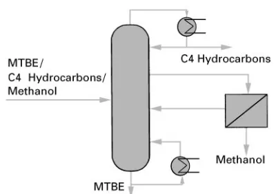
Institut Franc7ais du PeHtrole (IFP) has developed a process where pervaporation of methanol is used to debottleneck MTBE production. In the debutanizer columns used in MTBE processing, the MTBE} meth-anol azeotrope results in a concentration of methmeth-anol at a point midway between the feed tray and the reboiler (Figure 14). Pervaporating methanol out of the process from a side-draw taken at this point results in methanol free MTBE as debutanizer bottom product.
Separation systems based on pervaporation/vapour permeation of methanol offer the following beneRts: problem-free separation of methanol/organic mixtures irrespective of azeotrope formation; avoids water wash for methanol removal; minimum energy costs.
See Colour Plates 51, 52.
Further Reading
Bakish Material Crop (1985}1995) Proceedings of the (1st to7th)International Conference on Pervaporation Processes in the Chemical Industry. Englewood: Bakish Material Corp.
BoKddeker KW (ed.) (1995) The early history of membrane science,Journal of Membrane Science100.
Huang RY (ed.) (1991)Pervaporation Membrane Separ-ation Processes,I Membrane Science and Technology, Series 1. Amsterdam: Elsevier.