.
.
-
AT&T
I • • • • • • • • • • • • • • • • • • ~ • • ~.~ • • :~~. :~. : .
:.:.:.:.:.:.:.:.:.:.:.:.:.
:~:.:~~~.:.
I·.·.·.·.·.·.·.·.·.·.·.·.·.·.·.~:·
,.
,... .
':.:.:.:.:.:.:.:.:.:.:.: .:.:.:.:.:.:.:.:.:.
I • • • • • • • • • • • • • • • •
I:.:.:.:.:.:.:.:. :.:.:.:
.:.:.:.:.~.:~.:.
:.:.:.:.:.:.:.:.:.
·
... .
:.:.:.
:.:.:.:.:~:~. I • • • • • • • • • • • • • • • • ,... .
,... .
·
... .
:.:.:.:.:.:.:.:.:.:.
:.:.:.:.:.:.:~.~.I·.·.·.·.·.·.·.·.·.·.·.·.·.·.·.·· ·
I·.·.·.·.·.·.·.·.·.·.·.·.·.·.·
~...
I·.·.·.·.·.·.·.·.·.·.·.·.·.·.· .. '.
I·.·.·.·.·.·.·.·.·.·.·.·.·.·.·.·~·.·
· .
. . .
. . .
. ..
,.
IY --... _._.
a ~ • • • • • • • • • • • • • •
I.
\ ••••••••••••••••••• :::.;:; ' •• _
'.\ ~... ~.:
... .
'.~ .~·
..
-
... .
...
---~~... .
I
·
• • • • • • • • • • • • • •...
. .-:::::
.. .
I • • • • • • • • • • • • • • •
I·.·.·.·.·.·.·.·.·.·.·.·.·.·.· ·
I:.:.:.:.:.:.:. :.:.
:.:.:.:.:~:.:;1 • • • • • • • • • • • • • • •
·
...
~:~:_.-,
. . .
.
.
. .
..
'~.-.'-..
-· . . . .
·
:
.
:
.
:
.
:
.:
.
.
:
. . .
.
:
.:.:.:
. .
.
.-
,-.:.:.;.~ ~. ~. ~
..
-I:.:.:.:.:.:. :.:.:.:.:.:.:.:.:.:. ,.
I
·
. .
• • • • • • • • • • • • • • •... .
. .
.
.
. .
.
. .
. . . .
.
·
. .
... .
. . . .
.
.
. . .
.
.
. .
·
... .
.
:.:.:.:.:.:.:.:.:
.:
... .
· ...
..
307-229 Issue 1UNIX™ System V Release 3
STREAMS Primer
..
.. .
...•
. .
. .
-.
©1986 AT&T
All Rights Reserved Printed in USA
NOTICE
The information in this document is subject to change without notice. AT&T assumes no responsibility for any errors that may appear in this document.
Table of Contents
Chapter 1: Introduction
1-1How this Document is Organized 1-3
Other Documents 1-4
Chapter 2: Overview
2-1A Basic View' of a Stream
2-1System Calls 2-2
Benefits of STREAMS
2-3Creating Service Interfaces 2-3
Manipulating Modules 2-3
Protocol Portability 2-4
Protocol Substitution 2-5
Protocol Migration 2-5
Module Reusability 2-6
An
Advanced View of a Stream
2-8Stream Head 2-9
Modules 2-9
Stream End 2-10
Chapter 3: Building a Stream
3-1Expanded Streams 3-2
Table of Contents
Chapter 4: User Level Functions
STREAMS System Calls
An Asynchronous Protocol Stream Example
Initializing the Stream Message Types
Sending and Receiving Messages Using Messages in the Exam pIe
Other User Functions
Chapter 5: Kernel Level Functions
Introduction
Messages
Message Allocation
Put and Service Procedures
Put Procedures Service Procedures
Kernel Processing
Read Side Processing Driver Processing
CHARPROC CANONPROC
- - - Table of Contents
Chapter 6: Other Facilities
6-1Introduction
6-1Message Queue Priority
6-2Flow Control
6-4Multiplexing
6-7Monitoring
6-12Error and Trace Logging
6-13Chapter 7: Driver Design Comparisons
7-1Introduction
7-1Environment 7-1
Drivers 7-1
Modules 7-2
List of Figures
Figure 2-1: Basic Stream 2-1
Figure 2-2: Protocol Module Portability 2-5
Figure 2-3: Protocol Migration 2-6
Figure 2-4: Module Reusability 2-7
Figure 2-5: Stream In More Detail 2-8
Figure 3-1: Setting Up a Stream 3-1
Figure 4-1: Idle Stream Configuration for Example 4-3
Figure 4-2: Asynchronous Terminal Streams 4-8
Figure 5-1: A Message 5-2
Figure 5-2: Messages on a Message Queue 5-3
Figure 5-3: Operational Stream for Example 5-7
Figure 5-4: Module Put and Service Procedures 5-9
Figure 6-1: Streams Message Priority 6-3
Figure 6-2: Flow Control 6-5
Figure 6-3: Internet Multiplexing Stream 6-8
Figure 6-4: X.25 Multiplexing Stream 6-9
Introduction
With the addition of the Networking Support Utilities, UNIX System V Release 3.0 provides comprehensive support for networking services. This
Primer describes STREAMS, a major building block of that support. The Pri-mer provides a high level, technical overview of STREAMS; it is intended for managers and developers who have prior knowledge of the UNIX system and networking or other data communication facilities. For a more detailed description of STREAMS, see the STREAMS Programmer's Guide.
The UNIX system was originally designed as a general-purpose, multi-user, interactive operating system for minicomputers. Initially developed in the 1970's, the system's communications environment included slow to medium speed, asynchronous terminal devices. The original design, the communications environment, and hardware state of the art influenced the character input/output (I/O) mechanism but the character I/O area did not require the same emphasis on modularity and performance as other areas of the system.
Support for a broader range of devices, speeds, modes, and protocols has since been incorporated into the system, but the original character I/O mechanism, which processes one character at a time, made such develop-ment difficult. Additionally, a paucity of tools and the absence of a frame-work for incorporating contemporary netframe-working protocols added to the difficulty.
The current generation of networking protocols is exemplified by Open Systems Interconnection (051), Systems Network Architecture (SNA), Transmission Control Protocol/lnternet Protocol (TCP /IP), X.2S, and Xerox Network Systems (XNS). These protocols provide diverse functionality, lay-ered organization, and various feature options. When developing these pro-tocol suites, developers faced additional problems because there were no relevant standard interfaces in the UNIX system.
Introduction
AT&T decided to enhance the character I/O area in Release 3.0. The result is STREAMS, a general, flexible facility and a set of tools for develop-ment of UNIX system communication services. With STREAMS, developers can provide services ranging from complete networking protocol suites to individual device drivers.
STREAMS defines standard interfaces for character I/O within the UNIX
kernel, and between the kernel and the rest of the UNIX system. The associ-ated mechanism is simple and open-ended. It consists of a set of system calls, kernel resources, and kernel utility routines. The standard interface and open-ended mechanism enable modular, portable development and easy integration of higher performance network services and their com-ponents. STREAMS does not impose any specific network architecture. Instead, it provides a powerful framework with a consistent user interface that is compatible with the existing character I/O interface still available in
UNIX System V.
STREAMS modularity and design reflect the "layers and options" charac-teristics of contemporary networking architectures. The basic components in a STREAMS implementation are referred to as modules. These modules, which reside in the kernel, offer a set of processing functions and associated service interfaces. From user level, modules can be dynamically selected and interconnected to provide any rational processing sequence. Kernel programming, assembly, and link editing are not required to create the interconnection. Modules can also be dynamically "plugged into" existing connections from user level. STREAMS modularity allows:
• User level programs that are independent of underlying protocols and physical communication media.
• Network architectures and higher level protocols that are indepen-dent of underlying protocols, drivers, and physical communication media.
• Higher level services that can be created by selecting and connecting lower level services and protocols.
• Enhanced portability of protocol modules resulting from STREAMS'
Introduction
In addition to modularity, STREAMS provides developers with integral functions, a library of utility routines, and facilities that expedite software design and implementation. The principal facilities are:
• Buffer management - To maintain STREAMS' own, independent buffer pool.
• Flow control - To conserve STREAMS' memory and processing resources.
• Scheduling - To incorporate STREAMS' own scheduling mechanism.
• Multiplexing - For processing interleaved data streams, such as occur in SNA, X.2S, and windows.
• Asynchronous operation of STREAMS and user processes - Allows STREAMS-related operations to be performed efficiently from user level.
• Error and trace loggers - For debugging and administrative func-tions.
STREAMS is the standard for AT&T UNIX system data communications and networking implementations. The original STREAMS concepts were developed in the Information Sciences Research Division of AT&T Bell Laboratories (see "A Stream Input-Output System" in the October 1984 AT&T Bell Laboratories Technical Journal).
How this Document is Organized
The Primer is organized as follows:
• Chapter 2 provides an overview of the applications and benefits of STREAMS and the STREAMS mechanism.
• Chapter 3 describes how to set up a Stream from user level and how this initializatIon affects the kernel. This and following chapters are aimed at developers.
Introduction
• Chapter 5 describes kernel operations associated with the Chapter 4 example, together with a discussion of basic STREAMS kernel facili-ties.
• Chapter 6 includes kernel and user facilities not otherwise described.
• Chapter 7 compares certain design features of character I/O device drivers with STREAMS modules and drivers.
• The Glossary defines terms that are specific to STREAMS.
Other Documents
The STREAMS Programmer's Guide contains more detailed STREAMS infor-mation for programmers: how programmers can develop networking appli-cations with STREAMS user-level facilities and how system programmers can use STREAMS kernel-level facilities to build modules and drivers.
A Basic View of a Stream
"STREAMS" is a collection of system calls, kernel resources, and kernel utility routines that can create, use, and dismantle a "Stream". A Stream is a full-duplex processing and data transfer path between a driver in kernel space and a process in user space (see Figure 2-1).
Stream Head
Module
[image:14.452.98.377.144.418.2]Driver
Figure 2-1: Basic Stream
User Process
External Interface
__
y~e! .?p~c~__ _
Kernel Space
!
downstream(optional)
t
upstreamA Basic View of a Stream
Using a combination of system calls, kernel routines, and kernel utili-ties, STREAMS passes data between a driver and the Stream head in the form of messages. Messages that are passed from the Stream head toward the driver are said to travel downstream, and messages passed in the other direction travel upstream.
The Stream head transfers data between the data space of a user process and STREAMS kernel data space. Data sent to a driver from a user process are packaged into STREAMS messages and passed downstream. Messages arriving at the Stream head from downstream are processed by the Stream head, and data are copied into user buffers. STREAMS can insert one or more modules into a Stream between the Stream head and driver to perform intermediate processing of data passing between the Stream head and driver.
System Calls
Applications programmers can use the STREAMS facilities via a set of system calls. This system call interface is upward compatible with the exist-ing character I/O facilities. The open(2) system call will recognize a
STREAMS file and create a Stream to the specified driver. A user process can send and receive data using read(2) and write(2) in the same manner as with character files and devices. The ioct1(2) system call enables application programs to perform functions specific to a particular device. In addition, a set of generic STREAMS ioctl commands [see streamio(7)] support a variety of functions for accessing and controlling Streams. A close(2) will disman-tle a Stream.
open, close, read, write, and ioctl support the basic set of operations on Streams. In addition, new system calls support advanced STREAMS facilities. The poll(2) system call enables an application program to poll multiple Streams for various events. When used with the STREAMS I_SETSIG ioctl command, poll allows an application to process I/O in an asynchronous manner. The putmsg(2) and getmsg(2) system calls enable application pro-grams to interact with STREAMS modules and drivers through a service interface (described next).
These calls are discussed in this document and in the STREAMS
Programmer's Guide. They are specified in the Programmer's Reference Manual
Benefits of STREAMS
STREAMS offers two major benefits for applications programmers: easy creation of modules that offer standard data communications services, and the ability to manipulate those modules on a Stream.
Creating Service Interfaces
One benefit of STREAMS is that it simplifies the creation of modules that present a service interface to any neighboring application program, module, or device driver. A service interface is defined at the boundary between two neighbors. In STREAMS, a service interface is a specified set of messages and the rules for allowable sequences of these messages across the boun-dary. A module that implements a service interface will receive a message from a neighbor and respond with an appropriate action (for example, send back a request to retransmit) based on the specific message received and the preceding sequence of messages.
STREAMS provides features that make it easier to design various applica-tion processes and modules to common service interfaces. If these modules are written to comply with industry-standard service interfaces, they are called protocol modules.
In general, any two modules can be connected anywhere in a Stream. However, rational sequences are generally constructed by connecting modules with compatible protocol service interfaces. For example, a module that implements an X.2S protocol layer, as shown in Figure 2-2, presents a protocol service interface at its input and output sides. In this case, other modules should only be connected to the input and output side if they have the compatible X.2S service interface.
Manipulating Modules
Benefits of STREAMS
• User level programs can be independent of underlying protocols and physical communication media.
• Network architectures and higher level protocols can be independent of underlying protocols, drivers and physical communication media.
• Higher level services can be created by selecting and connecting lower level services and protocols.
Below are examples of the benefits of STREAMS capabilities to developers for creating service interfaces and manipulating modules.
All protocol modules used below were selected for illustrative purposes. Their use does not imply that AT&T offers such modules as products.
Protocol Portability
MACHINE A
---X.25 Protocol Layer Module -V I LAPB Driver Machine A \ \ I CONS INTERFACESAME
MODULE
LAPB INTERFACEDIFFERENT
DRIVER
Figure 2-2: Protocol Module Portability
Protocol Substitution
Benefits of STREAMS
MACHINE B
---X.25 Protocol Layer Module 1\ - - - - ---~ ILAPB \ Driver Machine B
\ I
Alternative protocol modules (and device drivers) can be interchanged on the same machine if they are implemented to an equivalent service in terface( s).
Protocol Migration
Figure 2-3 illustrates how STREAMS can migrate functions between ker-nel software and front end firmware. A common downstream service inter-face allows the transport protocol module to be independent of the number or type of modules below. The same transport module will connect without modification to either an X.25 module or X.25 driver that has the same ser-vice interface.
Benefits of STREAMS
where economics may preclude the use of front-end hardware, and also on a larger scale system where a front-end is economically justified.
Class 1 Transport Protocol 1\ - - - - ---1/ X.2S Packet Layer Protocol ,\ I
I
\LAPB
-I Driver
[image:19.455.46.383.91.317.2]/-\ I
Figure 2-3: Protocol Migration
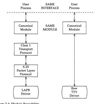
Module Reusability
SAME
MODULES
CONS InterfaceKERNEL
---1
IClass 1 Transport Protocol \ I
\
/-HARDWARE
\
J
~---~
X.2S
Packet Layer Driver
User Process - -- - - -
- -
--~ ~ Canonical Module I [image:20.453.76.399.77.413.2]Class 1 Transport Protocol
,
I X.2S Packet Layer Protocol ~ III I LAPB Driver \ IFigure 2-4: Module Reusability
SAME INTERFACE
SAME MODULE
Benefits of STREAMS
User Process -
-
-
--
- -
-
--~ ~ Canonical Module \ II Raw \
TTY
An Advanced View of a Stream
The STREAMS mechanism constructs a Stream by serially connecting ker-nel resident STREAMS components, each constructed from a specific set of structures. As described earlier and shown in Figure 2-5, the primary
STREAMS components are the Stream head, optional module(s), and Stream end.
Module B
Module
A
Message
"Ad"
"Bd"
QUEUE
[image:21.450.84.361.154.511.2]Module
Figure 2-5: Stream In More Detail
External Interface
___ lIs~r_S'p~c! ___ _ Kernel Space
"Bu"
: • • • • :"":;;:1. > r - - - ,
'--~.r__---'
QUEUE
Stream
End
Message
An Advanced View of a Stream
Stream Head
The Stream head provides the interface between the Stream and an application program. The Stream head processes STREAMS-related system calls from the application and performs the bidirectional transfer of data and information between the application (in user space) and messages (in STREAMS' kernel space).
Messages are the only means of transferring data and communicating within a Stream. A STREAMS message contains data, status/control informa-tion, or a combination of the two. Each message includes a specified mes-sage type indicator that identifies the contents.
Modules
A module performs intermediate transformations on messages passing between Stream head and driver. There may be zero or more modules in a Stream (zero when the driver performs all the required character and device processing).
Each module is constructed from a pair of QUEUE structures (see Au/ Ad and Bu/Bd in Figure 2-5). A pair is required to implement the bidirectional and symmetrical attributes of a Stream. One QUEUE performs functions on messages passing upstream through the module (Au and Bu in Figure 2-5). The other set (Ad and Bd) performs another set of functions on downstream messages. (A QUEUE, which is part of a module, is different from a message queue, which is described later.)
Each of the two QUEUEs in a module will generally have distinct func-tions, that is, unrelated processing procedures and data. The QUEUEs operate independently so that Au will not know if a message passes through Ad unless Ad is programmed to inform it. Messages' and data can be shared only if the developer specifically programs the module functions to perform the sharing.
An Advanced View of a Stream
Each QUEUE in a module may contain or point to messages, processing procedures, or data:
• Messages - These are dynamically attached to the QUEUE on a linked list ("message queue", see Au and Bd in Figure 2-5) as they pass through the module.
• Processing procedures - A put procedure, to process messages, must be incorporated in each QUEUE. An optional service procedure, to share the message processing with the put procedure, can also be incorporated. According to their function, the procedures can send messages upstream and/or downstream, and they can also modify the private data in their module.
• Data - Developers may provide private data if required by the QUEUE to perform message processing (for example, state information and translation tables).
In general, each of the two QUEUEs in a module has a distinct set of all of these elements. Additional module elements will be: described later. Although depicted as distinct from modules (see Figure: 2-5), a Stream head and the Stream end also contain a pair of QUEUEs.
Stream End
A Stream end is a module in which the module's processing procedures are the driver routines. The procedures in the Stream end are different from those in other modules because they are accessible from an external device and because the STREAMS mechanism allows multiple Streams to be connected to the same driver.
The driver can be a device driver, providing an interface between ker-nel space and an external communications device, or an internal pseudo-device driver. A pseudo-pseudo-device driver is not directly related to any external device, and it performs functions internal to the kernel. The multiplexing driver discussed in Chapter 6 is a pseudo-device driver.
Building
a Stream
A Stream is created on the first open(2) system call to a character special file corresponding to a STREAMS driver. A STREAMS device is distinguished from other character devices by a field contained in the associated cdevsw device table entry.
A Stream is usually built in two steps. Step one creates a minimal Stream consisting of just the Stream head and device driver, and step two adds modules to produce an expanded Stream (see Figure 3-1). The first step has three parts: head and driver structures are allocated and initialized; the modules in the head and end are linked to each other to form a Stream; the driver open routine is called.
Minimal STREAM
---STR~AM
HEAD
\
II
I
QUEUp pairI
raw TTY [image:24.452.64.411.229.463.2]device driver
Figure 3-1: Setting Up a Stream
Expanded STREAM
STR~AM
HEAD
CANO~PROC
module
raw TTY
device driver
Building a Stream
When the driver receives characters from the device, it places them into messages. The messages are then transferred to the next Stream component, the Stream head, which extracts the contents of the message and copies them to user space. Similar processing occurs for downstream character out-put; the Stream head copies data from user space into messages and sends them to the driver.
Expanded Streams
As the second step in building a Stream, modules can be added to the Stream. In the right-hand Stream in Figure 3-1, the CANONPROC module was added to provide additional processing on the characters sent between head and driver.
Modules are added and removed from a Stream in last-in-first-out (LIFO) order. They are inserted and deleted at the Stream head via the ioctl(2) system call. In the Stream on the left of Figure 2-4, the X.2S module was the first added to the Stream, followed by Class 1 Transport and Canon-ical modules. To replace the Class 1 module with a Class 0 module, the Canonical module would have to be removed first, then the Class 1 module, then a Class 0 module would be added and the Canonical module put back.
Because adding and removing modules resembles stack operations, the add is called a push and the remove a pop. Push and pop are two of the ioctl functions included in the STREAMS subset of ioctl system calls. These commands perform various manipulations and operations on Streams. The modules manipulated in this manner are called pushable modules, in con-trast to the modules contained in the Stream head and end. This stack ter-minology applies only to the setup, modification, and breakdown of a Stream.
Subsequent use of the word module will refer to those pushable modules between Stream head and end.
Building a Stream
the module template in the kernel. When a module is pushed, the template is located, the module structures for both QUEUES are allocated, and the template values are copied into the structures.
In addition to the module elements described in "A Basic View of a Stream" section of Chapter 2, each module contains pointers to an open rou-tine and a close rourou-tine. The open is called when the module is pushed, and the close is called when the module is popped. Module open and close procedures are similar to a driver open and close.
As in other files, a STREAMS file is closed when the last process open to it closes the file by a c1ose(2) system call. This system call causes the Stream to be dismantled (modules popped and the driver close executed).
Pushable Modules
Modules are pushed onto a Stream to provide special functions and/or additional protocol layers. In Figure 3-1, the Stream on the left is opened in a minimal configuration with a raw tty driver and no other module added. The driver receives one character at a time from the device, places the char-acter in a message, and sends the message upstream. The Stream head receives the message, extracts the single character, and copies it into the reading process buffer to send to the user process in response to a read(2) system call. When the user process wants to send characters back to the driver, it issues a write(2) system call, and the characters are sent to the Stream head. The head copies the characters into one or more multi-character messages and sends them downstream. An application program requiring no further kernel character processing would use this minimal Stream.
A user requiring a more terminal-like interface would need to insert a module to perform functions such as echoing, character-erase, and line-kill. Assuming that the CANONPROC module in Figure 3-1 fulfills this need, the application program first opens a raw tty Stream. Then, the CANONPROC
Building a Stream
Stream head implementation accommodates this change in format automatically and transfers the multiple-character data into user space. The Stream head also keeps track of messages partially transferred into user space (for example, when the current user read buffer can only hold part of the current message). Downstream operation is not affected: the head sends, and the driver receives, multiple character messages.
STREAMS System Calls
After a Stream has been opened, STREAMS-related system calls allow a user process to insert and delete (push and pop) modules. That process can then communicate with and control the operation of the Stream head, modules, and drivers, and can send and receive messages containing data and control information. This chapter presents an example of some of the basic functions available to STREAMS-based applications via the system calls. Additional functions are described at the end of this chapter and in Chapter 6.
The full set of STREAMS-related system calls is:
open(2)
close(2)
read(2)
write(2)
ioct1(2)
getmsg(2)
putmsg(2)
poU(2)
Open a Stream (described in Chapter 3)
Close a Stream (described in Chapter 3)
Read data from a Stream
Write data to a Stream
Control a Stream
Receive the message at Stream head
Send a message downstream
Notify the application program when selected events occur on a Stream
An Asynchronous Protocol Stream Example
In the example, our computer runs the UNIX system and supports different kinds of asynchronous terminals, each logging in on its own port. The port hardware is limited in function; for example, it detects and reports line and modem status, but does not check parity.
Communications software support for these terminals is provided via a
STREAMS implemented asynchronous protocol. The protocol includes a variety of options that are set when a terminal operator dials in to log on. The options are determined by a getty-type STREAMS user process, getstrm,
which analyzes data sent to it through a series of dialogs (prompts and responses) between the process and terminal operator.
The process sets the terminal options for the duration of the connection by pushing modules onto the Stream or by sending control messages to cause changes in modules (or in the device driver) already on the Stream. The options supported include:
• ASCII or EBCDIC character codes
• For ASCII code, the parity (odd, even or none) • Echo or not echo input characters
• Canonical input and output processing or transparent (raw) character handling
These options are set with the following modules:
CHARPROC Provides input character processing functions, including dynamically settable (via control messages passed to the module) character echo and parity checking. The module's default settings are to echo characters and not check character parity.
CANONPROC Performs canonical processing on ASCII characters upstream and downstream (note that this performs some processing in a different manner from the standard UNIX
system character I/O tty subsystem).
ASCEBC Translates EBCDIC code to ASCII upstream and ASCII to
An Asynchronous Protocol Stream Example
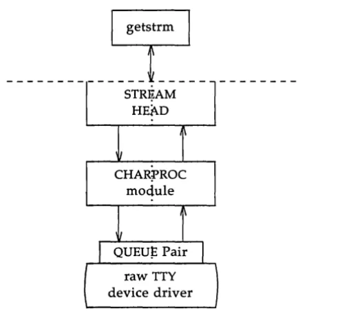
Initializing the Stream
At system initialization a user process,
getstrm,
is created for each tty port.getstrm
opens a Stream to its port and pushes the CHARPROC module onto the Stream by use of an ioctl I_PUSH command. Then, the process issues a getmsg system call to the Stream and sleeps until a message reaches the Stream head. The Stream is now in its idle state.The initial idle Stream, shown in Figure 4-1, contains only one pushable module, CHARPROC. The device driver is a limited function raw tty driver connected to a limited-function communication port. The driver and port transparently transmit and receive one unbuffered character at a time.
__________
~_:~i~~_~
________ _
STRI?AM HEAD
CHAR;rROC
module
raw TTY
[image:30.455.127.373.234.465.2]device driver
An Asynchronous Protocol Stream Example
Upon receipt of initial input from a tty port,
getstrm
establishes a con-nection with the terminal, analyzes the option requests, verifies them, and issues STREAMS system calls to set the options. After setting up the options,getstrm
creates a user application process. Later, when the user terminates that application,getstrm
restores the Stream to its idle state by use of system calls.The next step is to analyze in more detail how the Stream sets up the communications options. Before doing so, let's examine how messages are handled in STREAMS.
Message Types
All STREAMS messages are assigned message types to indicate their intended use by modules and drivers and to determine their handling by the Stream head. A driver or module can assign most types to a message it generates, and a module can modify a message's type during processing. The Stream head will convert certain system calls to specified message types and send them downstream, and it will respond to other calls by copying the contents of certain message types that were sent upstream. Messages exist only in the kernel, so a user process can only send and receive buffers. The process is not explicitly aware of the message type, but it may be aware of message boundaries, depending on the system call used (see the distinc-tion between getmsg and read in the next secdistinc-tion).
Most message types are internal to STREAMS and can only be passed from one STREAMS module to another. A few message types, including
M_DATA, M_PROTO, and M_PCPROTO, can also be passed between a Stream and user processes. M_DATA messages carry data within a Stream and between a Stream and a user process. M_PROTO or M_PCPROTO messages carry both data and control information. However, the distinction between control information and data is generally determined by the developer when implementing a particular Stream. Control information includes ser-vice interface information, carried between two Stream entities that present service interfaces, and condition or status information, which may be sent between any two Stream entities regardless of their interface. An
An Asynchronous Protocol Stream Example
Sending and Receiving Messages
putmsg is a STREAMS-related system call that sends messages; it is simi-lar to write. putmsg provides a data buffer which is converted into an M_DATA message, and can also provide a separate control buffer to be placed into an M_PROTO or M_PCPROTO block. write provides byte-stream data to be converted into M_DATA messages.
getmsg is a STREAMS-related system call that accepts messages; it is simi-lar to read. One difference between the two calls is that read accepts only data (messages sent upstream to the Stream head as message type M_DATA), such as the characters entered from the terminal. getmsg can simultane-ously accept both data and control information (message sent upstream as types M_PROTO or M_PCPROTO). getmsg also differs from read in that it preserves message boundaries so that the same boundaries exist above and below the Stream head (that is, between a user process and a Stream). read generally ignores message boundaries, processing data as a byte stream.
Certain STREAMS ioctl commands, such as I_STR, also cause messages to be sent or received on the Stream. I_STR provides the general "ioctl" capa-bility of the character I/O subsystem. A user process above the Stream head can issue putmsg, getmsg, the I_STR ioctl command, and certain other STREAMS related system calls. Other STREAMS ioctls perform functions that include changing the state of the Stream head, pushing and popping
modules, or returning special information. ioctl commands are described in more detail the STREAMS Programmer's Guide.
In addition to message types that explicitly transfer data to a process, some messages sent upstream result in information transfer. When these messages reach the Stream head, they are transformed into various forms and sent to the user process. The forms include signals, error codes, and call return values.
Using Messages in the Example
An Asynchronous Protocol Stream Example
An incoming call arrives at port one and causes a ring detect signal in the modem. The driver receives the ring signal, answers the call, and sends upstream an M_PROTO message containing information indicating an incom-ing call.
getstrm
is notified of all incoming calls, although it can choose to refuse the call because of system limits. In this idle state,getstrm
will also accept M_PROTO messages indicating, for example, error conditions such as detection of line or modem problems on the idle line.The M_PROTO message containing notification of the incoming call flows upstream from the driver into CHARPROC. CHARPROC inspects the message type, determines that message processing is not required, and passes the unmodified message upstream to the Stream head. The Stream head copies the message into the getmsg buffers (one buffer for control information, the other for data) associated with
getstrm
and wakes up the process.getstrm
sends its acceptance of the incoming call with a putmsg system call which results in a downstream M_PROTO message to the driver.Then,
getstrm
sends a prompt to the operator with a write and issues a getmsg to receive the response. A read could have been used to receive the response, but the getmsg call allows concurrent monitoring for control(M_PROTO and M_PCPROTO) information.
getstrm
will now sleep until the response characters, or information regarding possible error conditions detected by modules or driver, are sent upstream.The first response, sent upstream in a M_DATA block, indicates that the code set is ASCII and that canonical processing is requested.
getstrm
imple-ments these options by pushing CANONPROC onto the Stream, above CHAR-PROC, to perform canonical processing on the input ASCII characters.The response to the next prompt requests even parity checking.
getstrm
An Asynchronous Protocol Stream Example
As a result of the above dialogs, the terminal at port one operates in the following configuration:
• ASCII, even parity
• Echo
• Canonical processing
In similar fashion, an operator at a different type of terminal on port two requests a different set of options, resulting in the following
configuration:
• EBCDIC
• No Echo
• Canonical processing
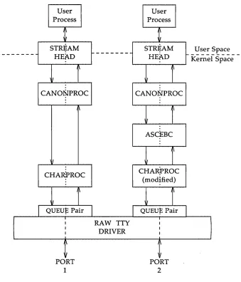
The resultant Streams for the two ports are shown in Figure 4-2. For port one, on the left, the modules in the Stream are CANONPROC and CHARPROC.
An Asynchronous Protocol Stream Example User Process STR~AM HEAD CANONPROC I' II CHARPROC
QUEUp Pair
I I I I
,
I PORT 1f---RAW TTY DRIVER
User Process
STR~AM
HEAD
t
r
CANONPROC
i
ASCEBCi
CHAR?ROC (modified)QUEUp Pair
[image:35.450.42.381.66.462.2]I I I I I I PORT 2
Figure 4-2: Asynchronous Terminal Streams
User Space
An Asynchronous Protocol Stream Example
Since CHARPROC is now performing no function for port two, it might have been popped from the Stream to be reinserted by
getstrm
at the end of connection. However, the low overhead of STREAMS does not require its removal. The module remains on the Stream, passing messages unmodified between ASCEBC and the driver. At the end of the connection,getstrm
restores this Stream to its idle configuration of Figure 4-1 by popping the added modules and then sending an I_STR to CHARPROC to restore the echo default.
Note that the tty driver shown in Figure 4-2 handles minor devices. Each minor device has a distinct Stream connected from user space to the driver. This ability to handle multiple devices is a standard STREAMS
Other User Functions
The previous example illustrates basic STREAMS concepts. Alternate, more efficient, STREAMS calls or mechanisms could have been used in place of those described earlier. Some of the alternatives are described in Chapter 6 and others are addressed in the STREAMS Programmer's Guide.
For example, the initialization process that created a getstrm for each tty port could have been implemented as a "supergetty" by use of the
STREAMS-related poll system call. As described in Chapter 6, poll allows a single process to efficiently monitor and control multiple Streams. The "supergetty" process would handle all of the Stream and terminal protocol initialization and would create application processes only for established connections.
The M_PROTO notification sent to getstrm could have been sent by the driver as an M_SIG message that causes a specified signal to be sent to the process. As discussed previously under "Message Types," error and status information can also be sent upstream from a driver or module to user processes via different message types. These messages will be transformed by the Stream head into a signal or error code.
Finally, an ~oct1 CSTR command could have been used in place of a
putmsg M_PROTO message to send information to a driver. The sending
Introduction
This chapter introduces the use of the STREAMS mechanism in the ker-nel and describes some of the tools provided by STREAMS to assist in the development of modules and drivers. In addition to the basic message pass-ing mechanism and QUEUE Stream linkage described previously, the
STREAMS mechanism consists of various facilities including buffer manage-ment, the STREAMS scheduler, processing and message priority, flow con-trol, and multiplexing. Over 30 STREAMS utility routines and macros are available to manipulate and utilize these facilities.
The key elements of a STREAMS kernel implementation are the process-ing routines in the module and drivers, and the preparation of required data structures. The structures are described in the STREAMS Programmer's
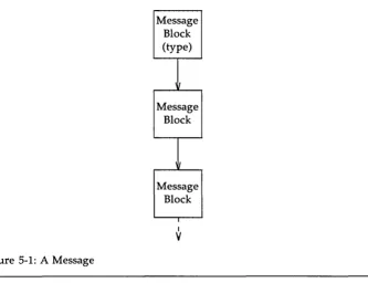
Messages
As shown in Figure 5-1, a STREAMS message consists of one or more linked message blocks. That is, the first message block of a message may be attached to other message blocks that are part of the same message. Multi-ple blocks in a message can occur, for examMulti-ple, as the result of processing that adds header or trailer data to the data contained in the message, or because of message buffer size limitations which cause the data to span mul-tiple blocks. When a message is composed of mulmul-tiple message blocks, the message type of the first block determines the type of the entire message, regardless of the types of the attached message blocks.
Message Block (type)
I
Message Block
II
Message Block
I
I
[image:39.451.54.387.193.449.2]V
Figure 5-1: A Message
Messages
link it after or before the initial message block. Both alternatives yield one new message.
Messages can exist standalone, as shown in Figure 5-1, when the mes-sage is being processed by a procedure. Alternately, a mesmes-sage can await processing on a linked list of messages, called a message queue, in a QUEUE.
In Figure 5-2, Message 1 is linked to Message 2.
I I queue I header <- - -r: ~
[image:40.451.42.408.151.400.2]Message Block (type)
~
Message Block~
~1essage Block I-Message
1
next messageFigure 5-2: Messages on a Message Queue I
I Message I Block I (type)
!
Message Block IV
Message
2
next<. - - - ->
message
When a message is on a queue, the first block of the message contains links to preceding and succeeding messages on the same message queue, in addi-tion to containing a link to the second block of the message (if present). The message queue head and tail are contained in the QUEUE.
Messages
Message Allocation
STREAMS maintains its own storage pool for messages. A procedure can request the allocation of a message of a specified size at one of three mes-sage pool priorities. The allocb utility will return a message containing a single block with a buffer of at least the size requested, providing there is a buffer available at the priority requested. When requesting priority for mes-sages, developers must weigh their process' need for resources against the needs of other processes on the same machine.
Message pool priority generally has no effect on allocation until the pool falls below internal STREAMS thresholds. When this occurs, allocb
may refuse a lower priority request for a message of size "x" while granting a higher priority request for the same size message. As examples of priority usage, storage for an urgent control message, such as an M_HANGUP or
Put and Service Procedures
The procedures in the QUEUE are the software routines that process messages as they transit the QUEUE. The processing is generally performed according to the message type and can result in a modified message, new message(s) or no message. A resultant message is generally sent in the same direction in which it was received by the QUEUE, but may be sent in either direction. A QUEUE will always contain a put procedure and may also con-tain an associated service procedure.
Put Procedures
A put procedure is the QUEUE routine that receives messages from the preceding QUEUE in the Stream. Messages are passed between QUEUEs by a procedure in one QUEUE calling the put procedure contained in the follow-ing QUEUE. A call to the put procedure in the appropriate direction is gen-erally the only way to pass messages between modules (unless otherwise indicated, "modules" infers "module, driver and Stream head"). QUEUEs in pushable (see Chapter 3) modules contain a put procedure. In general, there is a separate put procedure for the read and write QUEUEs in a module because of the "full duplex" operation of most Streams.
A put procedure is associated with immediate (as opposed to deferred, see below) processing on a message. Each module accesses the adjacent put procedure as a subroutine. For example, consider that modA, modB, and
mode are three consecutive modules in a Stream, with mode connected to the Stream head. If modA receives a message to be sent upstream, modA processes that message and calls modB's put procedure, which processes it and calls mode's put procedure, which processes it and calls the Stream head's put procedure. Thus, the message will be passed along the Stream in one continuous processing sequence. On one hand, this sequence has the benefit of completing the entire processing in a short time with low over-head (subroutine calls). On the other hand, if this sequence is lengthy al1d the processing is implemented on a multi-user system, then this manner of processing may be good for this Stream but may be detrimental for others since they may have to wait "too long" to get their turn at bat.
Put and Service Procedures
Stream head, which may have to wait until a process initiates a read(2) on the Stream.
Service Procedures
STREAMS allows a service procedure to be contained in each QUEUE, in addition to the put procedure, to address the above cases and for additional purposes. A service procedure is not required in a QUEUE and is associated with deferred processing. If a QUEUE has both a put and service procedure, message processing will generally be divided between the procedures. The put procedure is always called first, from a preceding QUEUE. After the put procedure completes its part of the message processing, it arranges for the service procedure to be called by passing the message to the putq routine. putq does two things: it places the message on the message queue of the QUEUE (see Figure 5-2) and links the QUEUE to the end of the STREAMS scheduling queue. When putq returns to the put procedure, the procedure typically exits. Some time later, the service procedure will be automatically called by the STREAMS scheduler.
The STREAMS scheduler is separate and distinct from the UNIX system process scheduler. It is concerned only with QUEUEs linked on the STREAMS scheduling queue. The scheduler calls the service procedure of the scheduled QUEUE in a FIFO manner, one at a time.
Having both a put and service procedure in a QUEUE enables STREAMS to provide the rapid response and the queuing required in multi-user sys-tems. The put procedure allows rapid response to certain data and events, such as software echoing of input characters. Put procedures effectively have higher priority than any scheduled service procedures. When called from the preceding STREAMS component, a put procedure executes before the scheduled service procedures of any QUEUE are executed.
Kernel Processing
The following continues the example of Chapter 4, describing STREAMS
kernel operations and associates them, where relevant, with Chapter 4 user-level system calls in the example. As a result of initializing operations and pushing a module, the Stream for port one has the following configuration:
write
I
STREAM
CANONPROC
module
CHARPROC
module
raw TTY
[image:44.451.125.408.145.365.2]device driver
Figure 5-3: Operational Stream for Example
1
readKernel Processing
Read Side Processing
In our example, read side processing consists of driver processing, CHARPROC processing, and CANONPROC processing.
Driver Processing
In the example, the user process has blocked on the getmsg(2) system call while waiting for a message to reach the Stream head, and the device driver independently waits for input of a character from the port hardware or for a message from upstream. Upon receipt of an input character inter-rupt from the port, the driver places the associated character in an M_DATA message, allocated previously. Then, the driver sends the message to the CHARPROC module by calling CHARPROC's upstream put procedure. On return from CHARPROC, the driver calls the allocb utility routine to get another message for the next character.
CHARPROC
CANONPROC
Module
CHARPROC
Module
Kernel Processing
write read
[image:46.450.116.403.73.307.2]...
V
(service) (service)A
(put) ...V
(service) .---_....1..-_--. (service)A
(put).
.
...Figure 5-4: Module Put and Service Procedures
When the driver calls CHARPROC's read QUEUE put procedure, the pro-cedure checks private data flags in the QUEUE. In this case, the flags indi-cate that echoing is to be performed (recall that echoing is optional and that we are working with port hardware which can not automatically echo). CHARPROC causes the echo to be transmitted back to the terminal by first making a copy of the message with a STREAMS utility. Then, CHARPROC uses another utility to obtain the address of its own write QUEUE. Finally, the CHARPROC read put procedure calls its write put procedure and passes it the message copy. The write procedure sends the message to the driver to effect the echo and then returns to the read procedure.
Kernel Processin~
After returning from echo processing, the CHARPROC read put pro-cedure checks another of its private data flags and determines that parity checking should be performed on the input character. Parity should most reasonably be checked as part of echo processing. However, for this exam-ple, parity is checked only when the characters are sent upstream. This relaxes the timing in which the checking must occur, that is, it can be deferred along with the canonical processing. CHARPROC uses putq to schedule the (original) message for parity check processing by its read ser-vice procedure. When the CHARPROC read serser-vice procedure is complete, it forwards the message to the read put procedure of CANONPROC. Note that if parity checking were not required, the CHARPROC put procedure would call the CANONPROC put procedure directly.
CANONPROC
CANONPROC performs canonical processing. As implemented, all read QUEUE processing is performed in its service procedure so that
CANONPROC's put procedure simply calls putq to schedule the message for its read service procedure and then exits. The service procedure extracts the character from the message buffer and place it in the "line buffer" contained in another M_DATA message it is constructing. Then, the message which contained the single character is returned to the buffer pool. If the charac-ter received was not an end-of-line, CANONPROC exits. Otherwise, a com-plete line has been assembled and CANONPROC sends the message upstream to the Stream head which unblocks the user process from the getmsg call and passes it the contents of the message.
Write Side Processing
The write side of this Stream carries two kinds of messages from the user process: ioctl messages for CHARPROC, and M_DATA messages to be output to the terminal.
Kernel Processing
For terminal output, it is presumed that M_DATA messages, sent by write system calls, contain multiple characters. In general, STREAMS returns to the user process immediately after processing the write call so that the process may send additional messages. Flow control, described in the next chapter, will eventually block the sending process. The messages can queue on the write side of the driver because of character transmission timing. When a message is received by the driver's write put procedure, the pro-cedure will use putq to place the message on its write-side service message queue if the driver is currently transmitting a previous message buffer. However, there is generally no write QUEUE service procedure in a device driver. Driver output interrupt processing takes the place of scheduling and performs the service procedure functions, removing messages from the queue.
Analysis
For reasons of efficiency, a module implementation would generally avoid placing one character per message and using separate routines to echo and parity check each character, as was done in this example. Nevertheless, even this design yields potential benefits. Consider a case where alternate, more intelligent port hardware was substituted. If the hardware processed multiple input characters and performed the echo and parity checking func-tions of CHARPROC, then the new driver could be implemented to present the same interface as CHARPROC. Other modules such as CANONPROC
Introduction
The previous chapters described the basic concepts of constructing a Stream and utilizing the STREAMS mechanism. Additional STREAMS
features are provided to handle characteristic problems of protocol imple-mentation, such as flow control, and to assist in development.
Message Queue Priority
As mentioned in the previous chapter, the STREAMS scheduler operates strictly FIFO so that each QUEUE's service procedure receives control in the order it was scheduled. When a service procedure receives control, it may encounter multiple messages on its message queue. This buildup can occur if there is a long interval between the time a message is queued by a put procedure and the time that the STREAMS scheduler calls the associated ser-vice procedure. In this interval, there can be multiple calls to the put pro-cedure causing multiple messages. The service propro-cedure always processes all messages on its message queue unless prevented by flow control (see next section). Each message must pass through all the modules connecting its origin and destination in the Stream.
QUEUE
queue header
Message Queue Priority
Message queue
···1
I I I
I
I I I
I I I I
1
' - -_ _ _ - - J I I I
IE High ~IE Ordinary >1
I Priority I Priori ty I
[image:52.452.56.412.75.224.2]Head Tail
Figure 6-1: Streams Message Priority
The priority mechanism operates as shown in Figure 6-1. Message queues are generally not present in a QUEUE unless that QUEUE contains a service procedure. When a message is passed to putq to schedule the
mes-sage for service procedure processing, putq places the message on the
mes-sage queue in priority order. High priority mesmes-sages are placed ahead of all ordinary priority messages, but behind any other high priority messages on the queue. STREAMS utilities deliver the messages to the processing service procedure FIFO within each priority class. The service procedure is unaware of the message priority and simply receives the next message.
Message priority is defined by the message type; once a message is created, its priority cannot be changed. Certain message types come in equivalent high/ordinary priority pairs (for example, M_PCPROTO and
Flow Control
Even on a well-designed system, general system delays, malfunctions, and excessive message accumulation on one or more Streams can cause the message buffer pools to become depleted. Additionally, processing bursts can arise when a service procedure in one module has a long message queue and processes all its messages in one pass. STREAMS provides two independent mechanisms to guard its message buffer pools from being depleted and to minimize long processing bursts at anyone module.
Flow control is only applied to normal priority messages (see previous sec-tion) and not to high priority messages.
The first flow control mechanism is global and automatic and is related to the message pool priority, discussed in the "Message Storage Pool" section of Chapter 5. When the Stream head requests a message buffer in response to a putmsg or write system call, it uses the lowest level of priority. Since buffer availability is based on priority and buffer pool levels, the Stream head will be among the first modules refused a buffer when the pool becomes depleted. In response, the Stream head will block user output until the STREAMS buffer pool recovers. As a result, output has a lower priority than input.
The second flow control mechanism is local to each Stream and advisory (voluntary), and limits the number of characters that can be queued for pro-cessing at any QUEUE in a Stream. This mechanism limits the buffers and related processing at anyone QUEUE and in anyone Stream, but does not consider buffer pool levels or buffer usage in other Streams.
The advisory mechanism operates between the two nearest QUEUEs in a Stream containing service procedures (see diagram on next page). Messages are generally held on a message queue only if a service procedure is present in the associated QUEUE.
Flow Control
message sent from downstream) and a driver may contain a downstream limit.
Flow control operates as follows:
1. Each time a STREAMS message handling routine (for example, putq) adds or removes a message from a message queue in a QUEUE, the limits are checked. STREAMS calculates the total size of all message blocks on the message queue.
2. The total is compared to the QUEUE high-water and low-water values. If the total exceeds the high-water value, an internal full indicator is set for the QUEUE. The operation of the service pro-cedure in this QUEUE is not affected if the indicator is set, and the service procedure continues to be scheduled.
3. The next part of flow control processing occurs in the nearest preceding QUEUE that contains a service procedure. In the diagram below, if D is full and C has no service procedure, then B is the nearest preceding QUEUE.
--1
QU:UEH
QU~UE
H
QU~UE ~
I I
I I
V
V
Message Message
[image:54.451.71.377.293.405.2]Queue Queue
Figure 6-2: Flow Control
4. The service procedure in B uses a STREAMS utility routine to see if a
QUEUE ahead is marked full. If messages cannot be sent, the scheduler blocks the service procedure in B from further execution. B remains blocked until the low-water mark of the full QUEUE, D, is reached.
Flow Control
6. When the service procedure processing on D causes the message block total to fall below the low water mark, the full indicator is turned off. Then, STREAMS automatically schedules the nearest preceding blocked QUEUE (B in this case), getting things moving again. This automatic scheduling is know as back-enabling a
QUEUE.
Note that to utilize flow control, a developer need only call the utility that tests if a full condition exists ahead, plus perform some housekeeping if
Multiplexing
STREAMS multiplexing supports the development of internetworking protocols such as IP and ISO CLNS, and the processing of interleaved data streams such as in SNA, X.2S, and terminal window facilities.
Multiplexing
Module
Ethernet Driver
User
Processes
AAA
... lI.. If.
~... .
Upper Multiplexor or
Module
IP Multiplexor
Driver
Module
[image:57.451.84.386.65.388.2]LAPB Driver
Figure 6-3: Internet Multiplexing Stream
802.2 Driver
Figure 6-3 shows an example of a lower multiplexor. This configuration would typically occur where internetworking functions were included in the system. This Stream contains two types of drivers: the Ethernet, LAPB,
and IEEE 802.2 are hardware device drivers that terminate links to other nodes; the IP (Internet Protocol) is a multiplexor.
Multiplexing
Figure 6-3 depicts the IP multiplexor as part of a larger Stream. The Stream, as shown in the dotted rectangle, would generally have an upper
TCP multiplexor and additional modules. Multiplexors could also be cas-caded below the IP driver if the device drivers were replaced by multiplexor drivers.
PVC Processes
SVC
Processes Processes
---~---LAPB Driver or
[image:58.450.132.391.159.439.2]Lower Multiplexor
Figure 6-4: X.2S Multiplexing Stream
...
)/... .
: Modules
...
:~... .
Figure 6-4 shows an upper multiplexor. In this configuration, the driver routes messages between the lower Stream and one of the upper Streams. This Stream performs X.2S multiplexing to multiple independent SVC
Multiplexing
STREAMS facilities that support multiple minor devices in a device driver. This figure also shows that more complex configurations can be built by having one or more multiplexed LAPB drivers below and multiple modules above.
Developers can choose either upper or lower multiplexing, or both, when designing their applications. For example, a window multiplexor would have a similar configuration to the X.2S configuration of Figure 6-4, with a window driver replacing Packet Layer, a tty driver replacing LAPB,
and the child processes of the terminal process replacing the user processes. Although the X.2S and window multiplexing Streams have similar
configurations, their multiplexor drivers would differ significantly. The IP
multiplexor of Figure 6-2 has a different configuration than the X.2S multi-plexor and the driver would implement its own set of processing and rout-ing requirements.
In addition to upper and lower multiplexors, more complex
configurations can be created by connecting Streams containing multiplex-ors to other multiplexor drivers. With such a diversity of needs for multi-plexors, it is not possible to provide general purpose multiplexor drivers. Rather, STREAMS provides a general purpose multiplexing facility. The facility allows users to set up the inter-module / driver plumbing to create multiplexor configurations of generally unlimited interconnection.
The connections are created from user space through specific STREAMS
ioctl system calls. In a lower multiplexor, multiple Streams are connected below an application-specific, developer-implemented multiplexing driver. The multiplexing facility will only connect Streams to a driver. The ioctl call configures a multiplexor by connecting one Stream at a time below the opened multiplexor driver. As each Stream is connected to the driver, the connection setup procedure identifies the Stream to the driver. The driver will generally store this setup information in a private data structure for later use.
Multiplexing
Monitoring
STREAMS allows user processes to monitor and control Streams so that system resources (such as CPU cycles and process slots) can be used effectively. Monitoring is especially useful to user-level multiplexors, in which a user process can create multiple Streams and switch messages among them (similar to STREAMS kernel-level multiplexing, described previ-ously).
User processes can efficiently monitor and control multiple Streams with two STREAMS system calls: poll(2) and the ioctl(2) I_SETSIG command. These calls allow a user process to detect events that occur at the Stream head on one or more Streams, including receipt of a data or protocol mes-sage on the read queue and cessation of flow control.
Synchronous monitoring is provided by use of poll alone; in this case,
the user process cannot continue processing until after the system call com-pletes. When the calls are used together, they allow asynchronous, or con-current, operation of the process and STREAMS input/output. This allows the user process to monitor the Stream while carrying on other activities.
To monitor Streams with poll, a user process issues that system call and specifies the Streams to be monitored, the events to look for, and the amount of time to wait for an event. poll will block the process until the
time expires or until an event occurs. If an event occurs, poll will return
the type of event and the Stream on which the event occurred.
Instead of waiting for an event to occur, a user process may want to monitor one or more Streams while processing other data. It can do so by issuing the ioctl I_SETSIG command, specifying one or more Streams and
events (as with poll). Unlike a poll, this ioctl does not force the user
pro-cess to wait for the event but returns immediately and will issue a signal when an event occurs. The process must also request signal(2) or sigset(2) to catch the resultant SIGPOLL signal.
If any selected event occurs on any of the selected Streams, STREAMS
will cause the SIGPOLL catching function to be executed in all associated requesting processes. However, the process(es) will not know which event occurred, nor on what Stream the event occurred. A process that issues the I_SETSIG can get more detailed information by issuing a poll after it detects
Error and Trace Logging
STREAMS includes error and trace loggers useful for debugging and administering modules and drivers.
Error and Trace Logging
.--..
---
.. .._---_
..-Error Log File
Strerr
I
module~
--...---
.._-
...-
.._---_
..Trace Log File
Strace
Trace Messages
Log Software
[image:63.450.38.410.62.381.2]Driver
Figure 6-5: Error and Trace Logging
User User
--1
driverI
strerr is intended to operate as a daemon process initiated at system startup. A call to strlog requesting an error to be logged causes an
Error and Trace Logging
A call to strlog requesting trace information to be logged causes a simi-lar M_PROTO message to be sent to strace(lM), which places it in a user designated file. strace is intended to be initiated by a user. The user can designate the modules/drivers and severity level of the messages to be accepted for logging by strace.
A user process can submit its own M_PROTO messages to the log driver for inclusion in the logger of its choice through putmsg(2). The messages must be in the same format required by the logging processes and will be switched to the logger(s) requested in the message.