ISSN Online: 2331-4249 ISSN Print: 2331-4222
DOI: 10.4236/wjet.2017.54B002 Oct. 12, 2017 12 World Journal of Engineering and Technology
The Feasibility Research on Distribution
Network Closed Loop Based on the Load
Transfer Model
Qi Yin
1, Rui Ding
1, Yongchun Zhao
2, Yanfen Liu
2, Xiaolin Liu
3 1State Grid Deyang Electric Power Supply Company, Deyang, China2Beijing Join Bright Digital Power Technology Co., Ltd., Beijing, China
3State Grid (Beijing) Energy Conservation Design and Research Institute Co. Ltd., Beijing, China
Abstract
With the continuous development of urban distribution network, most of the distribution network has formed a dual power supply mode. The traditional way of distribution network load operating mainly adopts the power method, while satisfied the requirements of the safety of power grid, but will cause ex-ternal short time power outages, poor user experience, realizing the distribu-tion network outage rearrangement of load is a necessary means to improve power supply reliability. This paper presents mathematical model of load trans-fer in distribution network. The diftrans-ferences of voltage of amplitude and phase angle on both sides are calculated by the power flow. According to the diffe-rential pressure to determine whether the loop can be closed at the loop oper-ation, thereby improving the success rate of operation.
Keywords
Power Flow, Surge Current, Closing Loop
1. Introduction
Along with the progress of the construction of the power grid, the grid of 35 kV and 10 kV distribution network structure gradually perfect, the most of the re-gion has achieved annular space truss structure. Under normal operation, the ring network of distribution network are somewhere open loop operation, dis-tribution network load by different main power supply, when the main power supply and distribution network components need power outage overhaul or ad-just the operation mode, often need to pour the distribution network load to another
How to cite this paper: Yin, Q., Ding, R., Zhao, Y.C., Liu, Y.F. and Liu, X.L. (2017) The Feasibility Research on Distribution Net-work Closed Loop Based on the Load Trans-fer Model. World Journal of Engineering and Technology, 5, 12-20.
https://doi.org/10.4236/wjet.2017.54B002
DOI: 10.4236/wjet.2017.54B002 13 World Journal of Engineering and Technology
power supply. Distribution network before electricity use “cold” means more, namely power brake way, this way will interrupt the power supply to users, de-pending on the operating mode and the complexity of interruption of power supply in the time range from a few minutes to half an hour Power short stop will cause greater damage to the user, before the power failure also need a lot of user related communication and coordination, seriously affecting the mainten-ance work schedule and efficiency.
Literature [1] to study the closed loop transient value impact on the safety of power grid puts forward the trend of transient value and voltage amplitude and phase Angle difference on either side of the closed loop. According to the wiring diagram of distribution network, this paper analyzes and summarizes several operation modes of 10kV distribution network. The simplified calculation model of the load is obtained by transferring the load to the mathematical method on both sides of the line. Power flow [2] calculation can predict changes in various loads and network structure changes will not endanger the safety of the system. In this paper, the rapid decoupling method [3] is used to calculate the power flow, select the appropriate power supply path, ensure the reliable power supply of the distribution network to the users, and improve the economics of the dis-tribution network [4], so as to improve the economic and social benefits of the power supply enterprises.
2. Principle of Distribution Network
2.1. Common Structure of Urban Distribution Network
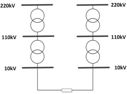
According to the wiring diagram can induce distribution network, 10 kV distri-bution network closed loop operation ways mainly have the following kinds.
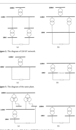
[image:2.595.269.479.554.708.2]Figure 1 is a feeder line contact between 220 kV networks. Figure 2 is the same 220 kV film network, a is a different 110 kV line partition feeder connec-tion; b is the same 110 kV line partition, different main transformer between the feeder. Figure 3 is the same plant, a is the same bus between the different feeder links; b is the bus between the different bus links. Figure 4 is the connection between the 220 kV main transformers 10 kV feed line.
DOI: 10.4236/wjet.2017.54B002 14 World Journal of Engineering and Technology
[image:3.595.212.536.43.599.2]
(a) (b) Figure 2. The diagram of 220 kV network.
(a) (b) Figure 3. The diagram of the same plant.
(a) (b) Figure 4. The diagram of the below of 220 kV main transformer.
2.2. Load Model
[image:3.595.216.366.70.251.2]DOI: 10.4236/wjet.2017.54B002 15 World Journal of Engineering and Technology
Assuming a uniform line of length L, the load S is evenly distributed over the
line. If the load is moved to the line on both sides, computation formula is as follows.
1 2
i j
S =S = S (1)
In the Formula (1), Si and Sj are the load values equivalent to S at both
ends of the line.
At present, the level of distribution automation is limited; most of the distri-bution load cannot be collected by SCADA system. SCADA system can only collect substation 10 kV outlet load. Therefore, the distribution load model is processed by the following method.
In Figure 5, b1 and bn are the outlet switches of the substation. b2, bn-1 is the
line contact switches. Sn1 is the total distribution capacity of lines b1-b2; Sni is the total distribution capacity of lines b2-b3; Snn-1 is the total distribution ca-pacity of lines bn-1-bn.
SCADA system can get the power of the switch, but cannot collect the load of the line. In this paper, the load is distributed by the coefficient method. The cal-culation formula of the load Si is as follows:
0 1
1
( )
i
i n n
i i
Sn
S S S
Sn
−
=
= +
∑
(2)2.3.
The Criterion of Distribution Network Closed Loop
According to the (State Grid Corporation of the power system voltage quality and reactive power management regulations [5]), the voltage difference below 220 kV should not exceed 20% of the rated voltage (including 220 kV).
If the breaker in Figure 6 is operated in a closed loop, the voltage difference on both sides of the breaker must meet the requirements of Equation (3).
1 2 1 2 20% 25 n V V V θ θ − <
− <
(3)
Equation (3) is the criterion for the loop operation.
Figure 5. The load model of distribution network.
Figure 6. The diagram of closed loop.
Station 1
10kV bus b1 b2 bn-1 bn 10kV busStation 2
S1 Si Sn-1 Sn
S0
Sn1 Sni Snn-1
Station 1
10kV bus b1 b2 bn-1 bn 10kV busStation 2
S1 Si Sn-1 Sn
S0
DOI: 10.4236/wjet.2017.54B002 16 World Journal of Engineering and Technology
2.4. The Surge Current Model of Closed Loop
There are two main reasons for the distribution of loops [6] [7]. The first is the voltage difference between the 10 kV buses on both sides of the loop switch. The second is the difference between the closed loop switch on both sides of the sys-tem short circuit impedance.
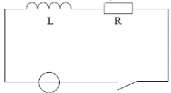
Figure 7 is a simple distribution network system. The normal operation con-tact switch is disconnected and the concon-tact switch is closed when the equipment is overhauled or under load. Because of the existence of contact switch voltage difference on both sides, so the system can produce surge current. Since the sys-tem has three-phase symmetry, it can only study one of the phases, such as L1 single-phase. Figure 8 is an equivalent circuit for calculating the transient surge current. In Figure 8, L and R are the equivalent inductance and resistance of all the electrical components in the loop, and the voltage difference on both sides of the loop is equivalent to the voltage source in the model.
The excitation in the calculation model is the phase voltage of the L1 phase.
(4)
is the voltage difference on both sides of the contact switch.
[image:5.595.236.541.301.703.2](5)
Figure 7. The closed loop of network.
[image:5.595.286.460.608.703.2]DOI: 10.4236/wjet.2017.54B002 17 World Journal of Engineering and Technology
The instantaneous value of the loop current should satisfy the following diffe-rential equation.
maxsin( )
di
E t Ri L
dt
ω α+ = + (6)
α is the initial phase angle of E. It is determined by the phase angle
differ-ence between the voltages on both sides of the initial time. The calculation of the surge current is as follows.
( / )
( ) R L tsin( ) sin( )
i t = −Me−
α ϕ
− +Mω α ϕ
t+ − (7)max
2 2 2
E M
R ω L
=
+ is the amplitude of the loop current component.
( L) arctg
R ω
ϕ= is the phase angle between the periodic component and
ϕ
.The maximum surge current IM is calculated as follows.
1.62( ) 2 m M I I = m
I is the amplitude of the closed loop steady current
3. The Calculation of Power Flow
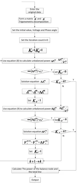
Power flow calculation is one of the most basic and important calculations in power system analysis. Typical computational methods include Gauss-Seidel method, Newton-Raphson method and Van Amidogen’s BX universal fast decoupling me-thod. The fast decoupling method overcomes the problem that the R > x net-work cannot converge. In this paper, the fast decoupling method is used to cal-culate the power flow [8].
Fast decoupling method is the main method of power flow calculation. The basic idea is that the node power is expressed as the polar coordinate formal of the voltage vector, and the active power error is used as the basis for correcting the voltage vector angle, the reactive power error is used as the basis for the cor-rection voltage amplitude. The iterations of active power and reactive power are carried out separately. The characteristics of fast decoupling method are to im-prove the computing speed, lower demand for computer storage capacity.
Fig-ure 9 is the diagram of P-Q power flow.
Active power imbalance equation is
1 ( cos sin ) 0 ( 1, 2, , 1)
n
i is i is i j j ij ij ij ij
P P P P V =V G δ B δ i n
∆ = − = −
∑
+ = = − (8)Reactive power imbalance equation is
1 ( sin cos ) 0 ( 1, 2, , )
n
i is i is i j j ij ij ij ij
Q Q Q Q V =V G δ B δ i m
∆ = − = −
∑
− = = (9)4. The Study of Case
DOI: 10.4236/wjet.2017.54B002 18 World Journal of Engineering and Technology
DOI: 10.4236/wjet.2017.54B002 19 World Journal of Engineering and Technology
overloaded. During the whole operation, the 10 kV bus voltage of the substation within the ring does not allow the limit.
Surge current is transient variable. It does not last more than five cycles, so most of the non-periodic component decays to zero within 0.1 s.
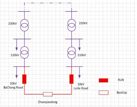
Through the study of the modeling and simulation of power grid connection diagram in Figure 10, get the phase Angle and voltage difference on both sides of the closed loop point value. According to the regulations of the voltage and the phase Angle deviation request, to determine whether the contact switch can be closed operation.
Figure 11 is closed loop impulse current waveform. The waveform shows that the aperiodic component of the surge current decays to zero in the five periodic waves, and the maximum amplitude appears half a cycle after the closed loop op-eration.
[image:8.595.263.485.324.497.2]From Table 1, Table 2, it can be seen that the magnitude and phase angle of the voltage differentials on both sides of the loop are meet the conditions of Formula (3), so that the closed loop operation can be performed at the Zhaoqiaodong.
[image:8.595.208.538.548.599.2]Figure 10. The diagram of typical wiring of Deyang.
Table 1. The information of current of closed loop of Zhaqiaodong.
[image:8.595.208.538.633.732.2]Closed loop point Before After Circulation Lu Road side 271.5927∠0.24 Å 141.2265∠0.2 Å 130.3662∠0.27 Å Bachang Road side 21.1661∠0.35 Å 148.0599∠0.17 Å 126.8940∠180.14 Å
Table 2. The information of voltage of closed loop of Zhaqiaodong.
Lu
Road side Road side Difference Percentage % Reference Conclusion Bachang Voltage
amplitude (kV) 9.9422 9.794 0.1482 1.482 20.00% correspond
Voltage
DOI: 10.4236/wjet.2017.54B002 20 World Journal of Engineering and Technology
Figure 11. The diagram of surge current of closed loop.
5. Conclusion
Using the distribution network load model to do power flow calculations put forward in this article, and calculate the difference between the phase angle and the voltage difference on both sides of the loop. This difference compared with closed loop conditions, and then determines whether can be closed loop opera-tion. The simulation of typical grid, to validate the distribution network load of the simplified model is reasonable.
References
[1] Liu, L., Yu, H.R. and Jin, X. (2008) Analysis of Loop Power Flow’s Transient Process. Mechanical & Electrical Engineering Magazine, 25, 74-76.
[2] Xia, X., Xiong, J. and Hu, L.X. (2004) Analysis and Control of Loop Power Flow in Regional Power Network. Power System Technology, 28, 76-80.
[3] Lv, B.L., Liu, M. and Xu, T.F. (2013) Comparison of Flow Calculation Methods for Quick Decoupling. Jiangxi Electric Power, 37, 67-69 + 89.
[4] http://www.chinaqking.com/yc/2012/254556.html
[5] Rules for the Operation of Power System Operation. State Grid Corporation of China.
[6] Chen, X., Wang, L. and Li, Y. (2005) Analysis of Surge Current Due to Closing Loop in Distribution Grid. Electric Power Automation Equipment, 25, 40-42.
[7] Qiu, G.Y. (1999) Current. Higher Education Press, Beijing.