EVOLUTIONARY TRENDS IN LIGHTWAVE COMMUNICATIONS
Department of Physics Kamla Nehru Institute of Physical and Social Sciences, Sultanpur (UP)
ARTICLE INFO ABSTRACT
The optical fiber as the transmission medium for lightwave communication is now well established. Optical
transmission medium of choice for long distance and high data rate transmission. Networks which operate at the 1300 nm window are now in state of art situation. Advanced fiber
at lowest loss 1550 nm window are reaching to state of art situation for long haul routes. These systems are based on dispersion shifted fibers and erbium
fiber amplifiers (EDFAs) provide large
division multiplexed information channels can be transmitted and simultaneously provided gain by EDFAs. The use of erbium
fibers.
this paper is to trace the evolutionary trends in fiber optic communications seen since the first low loss fiber. Some nonlinear optical effects that are importan
communication systems will also be discussed.
Copyright © 2017, Sunil P. Singh. This is an open access distribution, and reproduction in any medium, provided
INTRODUCTION
In light wave communication light pulses are used to transfer information from one point to another through an optical fiber. The information transmitted is essentially digital information generated by telephone systems, cable television companies, and computer systems. An optical fiber is a dielectric cylindrical waveguide made from low-loss materials, usually silicon dioxide. Light wave communication systems consists of an optical transmitter to convert an electrical signal to an optical signal for transmission through the optical fiber, a cable containing several bundles of optical fibers, optical amplifiers to boost the power of the optical signal, and an optical receiver to reconvert the received optical signal back to the original transmitted electrical signal. The Figure (1) gives a simplified description of a basic fiber optic communication system. than four decades have passed since the announcement of first low-loss fiber. In this announcement, the authors reported fabrication of single-mode fiber by vapour
process, which exhibited a loss of 20 dB/km at He
wave length (Agrawal, 2002). Fiber losses have steadily decreased and become 0.15 dB/km in a state of art fiber, whic is almost theoretical achievable lowest loss in silica fibers. At the same time continuous wave operation of GaAlAs semiconductor laser was demonstrated as a source for optical communication.
*Corresponding author: Sunil P. Singh,
Department of Physics Kamla Nehru Institute of Physical and Social Sciences, Sultanpur (UP)-228118, India.
ISSN: 0975-833X
Vol.
Article History:
Received 10th September, 2017 Received in revised form 07th October, 2017
Accepted 24th November, 2017 Published online 27th December, 2017
Citation: Sunil P. Singh. 2017. “Evolutionary Trends in Lightwave Communications
Key words:
Fiber optics, Communication, Laser, Optical fiber amplifier, Nonlinear effects, Dispersion, Optical fiber, Wavelength division multiplexing, and Optical network.
RESEARCH ARTICLE
EVOLUTIONARY TRENDS IN LIGHTWAVE COMMUNICATIONS
*Sunil P. Singh
Department of Physics Kamla Nehru Institute of Physical and Social Sciences, Sultanpur (UP)
ABSTRACT
The optical fiber as the transmission medium for lightwave communication is now well established. Optical fibers provide enormous and unsurpassed transmission bandwidth, and are now the transmission medium of choice for long distance and high data rate transmission. Networks which operate at the 1300 nm window are now in state of art situation. Advanced fiber
at lowest loss 1550 nm window are reaching to state of art situation for long haul routes. These systems are based on dispersion shifted fibers and erbium-doped fiber amplifiers. The erbium fiber amplifiers (EDFAs) provide large and broad band optical gains. Large number of wavelength division multiplexed information channels can be transmitted and simultaneously provided gain by EDFAs. The use of erbium-doped fiber amplifier increases the power confinement inside optical Therefore in such systems effects of optical nonlinearities may become important. The aim of this paper is to trace the evolutionary trends in fiber optic communications seen since the first low loss fiber. Some nonlinear optical effects that are importan
communication systems will also be discussed.
access article distributed under the Creative Commons Attribution License, the original work is properly cited.
In light wave communication light pulses are used to transfer information from one point to another through an optical fiber. The information transmitted is essentially digital information phone systems, cable television companies, and computer systems. An optical fiber is a dielectric loss materials, usually silicon dioxide. Light wave communication systems consists of electrical signal to an optical signal for transmission through the optical fiber, a cable containing several bundles of optical fibers, optical amplifiers to boost the power of the optical signal, and an optical receiver signal back to the original transmitted electrical signal. The Figure (1) gives a simplified description of a basic fiber optic communication system. More than four decades have passed since the announcement of first the authors reported mode fiber by vapour-phase oxidation process, which exhibited a loss of 20 dB/km at He-Ne laser . Fiber losses have steadily decreased and become 0.15 dB/km in a state of art fiber, which is almost theoretical achievable lowest loss in silica fibers. At the same time continuous wave operation of GaAlAs semiconductor laser was demonstrated as a source for optical
Department of Physics Kamla Nehru Institute of Physical and Social
The development of low-loss fiber and GaAlAs semiconductor lasers paved the way for rapid introduction of optics in communication networks (Ramaswa
the discovery of transistors, we have noticed such a fantastic growth rate of any new technology.
1960s demonstrated the capability of waveguides to transport information encoded in light signals. But it was n
invention of low-loss optical fiber in the early 1970s that optical fiber transmission systems really took off. The silica based optical fiber has three low
1300 and 1550 nm wavelength bands with the lowest loss being about 0.2 dB/km in 1550 nm band
loss profile and operating windows of silica fiber is shown in Figure (2). These fibers enabled transmission of light signals over distances of several tens of kilometers before they needed to be regenerated. The last 45 years of research and development activities in field of fiber optics can be grouped into several distinct generations. In every generation, bit distance product increases initially and begins to saturate as the technology matures (Ramaswami
1992). The evolution of terrestrial and undersea optical fiber transmission systems is shown in Figure (3).
First Generation Systems
The first generation of lightwave systems used light diodes (LEDs) or multilongitudinal mode (MLM) Fabry laser transmitters in the 800 nm wavelength band, silicon photo detectors and multimode step-index fibers.
International Journal of Current Research
Vol. 9, Issue, 12, pp.62297-62304, December, 2017
Evolutionary Trends in Lightwave Communications”, International Journal of Current Research
Available online at http://www.journalcra.com
z
EVOLUTIONARY TRENDS IN LIGHTWAVE COMMUNICATIONS
Department of Physics Kamla Nehru Institute of Physical and Social Sciences, Sultanpur (UP)-228118, India
The optical fiber as the transmission medium for lightwave communication is now well established. fibers provide enormous and unsurpassed transmission bandwidth, and are now the transmission medium of choice for long distance and high data rate transmission. Networks which operate at the 1300 nm window are now in state of art situation. Advanced fiber designs for operation at lowest loss 1550 nm window are reaching to state of art situation for long haul routes. These doped fiber amplifiers. The erbium-doped and broad band optical gains. Large number of wavelength division multiplexed information channels can be transmitted and simultaneously provided gain by doped fiber amplifier increases the power confinement inside optical Therefore in such systems effects of optical nonlinearities may become important. The aim of this paper is to trace the evolutionary trends in fiber optic communications seen since the first low loss fiber. Some nonlinear optical effects that are important for designing of fiber optic
License, which permits unrestricted use,
loss fiber and GaAlAs semiconductor lasers paved the way for rapid introduction of optics in Ramaswami, 1998). Rarely, since the discovery of transistors, we have noticed such a fantastic
growth rate of any new technology. Early experiments in
1960s demonstrated the capability of waveguides to transport information encoded in light signals. But it was not until the loss optical fiber in the early 1970s that optical fiber transmission systems really took off. The silica based optical fiber has three low-loss windows in the 800, 1300 and 1550 nm wavelength bands with the lowest loss about 0.2 dB/km in 1550 nm band (Agrawal, 2002). The loss profile and operating windows of silica fiber is shown in Figure (2). These fibers enabled transmission of light signals over distances of several tens of kilometers before they needed The last 45 years of research and development activities in field of fiber optics can be grouped into several distinct generations. In every generation, bit-rate-distance product increases initially and begins to saturate as the
Ramaswami, 1998; Keiser, 2000; Pal, . The evolution of terrestrial and undersea optical fiber transmission systems is shown in Figure (3).
The first generation of lightwave systems used light-emitting multilongitudinal mode (MLM) Fabry-Perot laser transmitters in the 800 nm wavelength band, silicon photo
index fibers.
INTERNATIONAL JOURNAL OF CURRENT RESEARCH
Figure 1. Basic optical fiber communication system
Figure 2. Loss profile and operating windows of s
(a)
(b)
(c)
(d)
(e)
iber communication system
Loss profile and operating windows of silica fiber
(f)
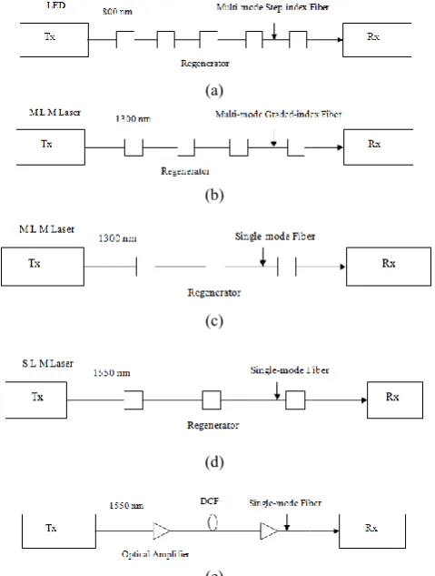
Figure 3. Evolution of optical fiber transmission systems. early system using LEDs over multi
System using multi-mode graded
Second generation system using MLM lasers over single fiber in the 1300 nm band to overcome modal dispersion in multimode fiber. (d) A later system using the 1550 nm band for lower loss and using SLM lasers to overcome chromatic dispersion limits. (e) Fourth generation single
1550 nm using optical amplifiers. (f) Current system using multiple wavelengths at amplifiers
The bit rate of these systems were limited to almost 20 Mb/s and require regenerators every few kilometers to regenerate the signal, which was degraded primarily due to modal dispersion. The spacing between regenerators corresponded to spacings between the exchanges typically encountered within the metropolis throughout the world and thus repeater less metropolitan area networks could be contemplated. This implied immediate decrease in installation and mai
costs associated with conventional coaxial systems due to elimination of repeaters. The choice of operating wavelength 800 nm was quit natural because of ready availability of commercial grade efficient light sources. Some of the initial telephone system field trials in the USA were carried out during 1977-79 by GTE in Los Angles and by AT & T in Chicago (Basch, 1978; Schwartz
demonstrated in Europe and Japan also 1984). Such systems become availabl 1980s.
Second Generation Systems
In 1975, Southampton University Group from England had reported that material dispersion in silica vanishes at a wavelength nearly 1300 nm (
[image:2.595.44.284.464.781.2]shows variation of material, waveguide and total dispersion with respect to wavelength.
Figure 4. Variation of material, waveguide with wavelength
(f)
Evolution of optical fiber transmission systems. (a) An early system using LEDs over multi-mode step-index fiber. (b) mode graded-index fiber in 1300 nm band. (c) Second generation system using MLM lasers over single-mode fiber in the 1300 nm band to overcome modal dispersion in mode fiber. (d) A later system using the 1550 nm band for lower loss and using SLM lasers to overcome chromatic dispersion limits. (e) Fourth generation single-channel system at 1550 nm using optical amplifiers. (f) Current-generation WDM iple wavelengths at 1550 nm and optical
The bit rate of these systems were limited to almost 20 Mb/s and require regenerators every few kilometers to regenerate the signal, which was degraded primarily due to modal dispersion. en regenerators corresponded to spacings between the exchanges typically encountered within the metropolis throughout the world and thus repeater less metropolitan area networks could be contemplated. This implied immediate decrease in installation and maintenance costs associated with conventional coaxial systems due to elimination of repeaters. The choice of operating wavelength 800 nm was quit natural because of ready availability of commercial grade efficient light sources. Some of the initial system field trials in the USA were carried out 79 by GTE in Los Angles and by AT & T in Schwartz, 1978). Similar links were demonstrated in Europe and Japan also (Basch, 1978; Koenig, . Such systems become available commercially in early
In 1975, Southampton University Group from England had reported that material dispersion in silica vanishes at a (Payne, 1975). The Figure (4) variation of material, waveguide and total dispersion
[image:2.595.318.554.597.752.2]The second generation systems deployed in the early 1980s used single-mode fiber as a means of eliminating modal dispersion, along with multilongitudinal mode Fabry-Perot lasers in the 1300 nm wavelength band. This effectively eliminated modal dispersion and enabled a dramatic increase in the bit-rates and distances possible between regenerators. These systems typically had regenerator spacings of about 40 km and operated at bit rates of a few hundred Mb/s. It was later found that the wavelength of zero material dispersion shifts to a longer wavelength when silica is doped with index modifiers
like GeO2 and P2O5. The material dispersion in silica is about
90 ps/nm-km at 800 nm, 0.1 ps/nm-km at 1300 nm and it rises to about 20 ps/nm-km at 1550 nm (Agrawal, 2002; Pal, 1992). The next step in this evolution in late 1980s was to deploy systems in the 1550 nm wavelength window to take advantage of the lower loss in this window relative to the 1300 nm window, so as to have longer spans between regenerators. The second generation of fiber-optic communication systems became available in the late 1980s.
Third Generation Systems
The introduction of third generation lightwave systems operating at 1550 nm was considerably delayed by large fiber dispersion near 1550 nm in single-mode fibers. In mid 1980s, it was realized that a considerable advantage in terms of pushing repeater spacings to longer distances can be achieved if the fiber designs could be so tailored to shift zero dispersion wavelength to coincide with the lowest loss wavelength of 1550 nm. Fiber manufacturers overcome this limitation by creating the dispersion-shifted fibers which have zero dispersion in the 1550 nm wavelength window. Thus, 1550 nm systems attracted much attention for high-capacity long-span terrestrial and undersea transmission links. The most common types of laser diodes available for operation at 1550 nm are Fabry-Perot (FP) and Distributed Feedback (DFB) lasers based on InGaAsP semiconductors. FP lasers are characterized by broader spectral width than DFB lasers. But the cost and chirping effects in DFB lasers compelled to choose FP lasers for optimum use of the 1550 nm wavelength window. Third generation optical fiber systems operating at 2.5 Gb/s over 100 km became available commercially in 1990. The highest bit-rate achieved was about 10 Gb/s by using dispersion-shifted fibers in combination with lasers oscillating in a single longitudinal mode (Agrawal, 2002; Ramaswami, 1998; Keiser, 2000; Pal, 1992). Enhancement in repeater spacing (which was typically 60-70 km) was a main challenge before researchers and lightwave industry in third generation systems. By using homodyne or heterodyne detection scheme (which improves receiver sensitivity) the repeater spacing can be increased. This led to development of coherent lightwave systems during 1980s (Franz, 2000). However, the advent of fiber amplifiers in 1989 postponed the commercial introduction of coherent communication systems.
Fourth Generation Systems
The growing demand for telecommunication services were seen in late 1980s. Optical fibers were used in almost all
segments of telecommunications, terrestrial long-haul
networks, between cities, in-city network between switching offices in metropolitan areas, undersea cables spanning oceans and subscriber loops that serve customer premises. The typical state of art repeaterless transmission distances were about 40-50 km at 560 Mb/s transmission rate. Since maximum
launched optical power was below 100 µW, it was difficult to improve system lengths beyond these specifications and use of electronic repeaters became inevitable. At a repeater, three functions-reshaping, retiming and reclocking are performed. However, these complex functions are expensive and require unit replacement in case of network capacity upgradation in terms of higher bit transmission rates. Since these units are required to convert photons to electrons and back to photons, often at modulation rates approaching the limits of current electronic switching technology, a bottleneck was encountered in late 1980s (Ramaswami, 1998). An optical amplifier was needed to bypass this electronic bottleneck.
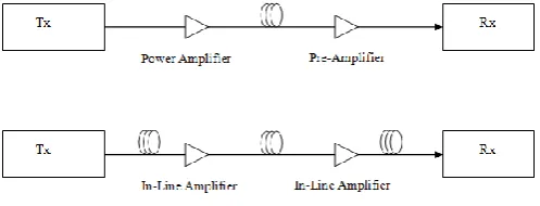
[image:3.595.310.559.390.485.2]The invention of erbium-doped fiber amplifiers (EDFAs) in 1989 gave a major boost to fiber transmission capacity. The concept of optical amplification is as old as laser itself. In 1963, Koester and Snitzer (Koester, 1994) had demonstrated a gain of 40 dB at 1060 nm in flash lamp side pumped one meter long Nd-doped fiber. The motivation at that time was to find optical sources for communication but development of semiconductor lasers pushed fiber lasers to background. Today erbium-doped fiber amplifier looks like an outstanding breakthrough but it is really an old idea. The fourth generation of lightwave systems makes use of optical amplification for increasing the repeater spacing. Significant cost reductions become possible by replacing the regenerators with EDFAs. The Figure (5) shows three different configurations in which an erbium-doped fiber amplifier can be used.
Figure 5. Three different configurations-power amplifier, pre-amplifier, and in-line amplifier in which an EDFA can be used
The EDFAs provide another major benefit: being transparent to bit-rates and modulation formats, it effectively allows the system to be upgraded in bit-rates at a later date by changing only the equipment at the ends of the link. Another major advantage of erbium-doped fiber amplifiers is that they are capable of amplifying signals at many wavelengths simultaneously (10-12). This provided another way of increasing the system capacity by using wavelength-division multiplexing (WDM) technique. In 1991, an experiment demonstrated the possibility of data transmission over 21000 km at 2.5 Gb/s, and over 14300 km at 5 Gb/s, using a
recirculating-loop configuration (Welsh et al., 1996). This idea
led the birth of transatlantic and transpacific cable systems. The 27000 km fiber optic link around the globe became operational in 1998, linking many Asian and European countries. A global network covering 250000 km with capacity of 2.5 Tb/s (64 WDM channels) came into operation by 2003 (Ramaswami, 1998; Keiser, 2000). Chromatic dispersion is still a major factor affecting the design of these systems. In addition, nonlinear effects in fiber, the nonflat gain spectrum of EDFAs and polarization-related effects are now becoming significant impairments preventing further increase in transmission capacity (Agrawal, 1995; Clesca, 1994; Sunil
et al., 2012).
Fifth Generation Systems
The fifth generation systems attempt to extend the wavelength range of WDM systems and to increase the bit rate of each channel within the WDM signal (Nusinsky, 2004; Rosolem, 2006; Potenza, 1996). This led to utilization of dense wavelength-division multiplexing (DWDM) techniques. In 2000, up to 27 WDM channels each operating at 20 Gb/s were transmitted over 9000 km using hybrid amplification scheme
(Agrawal, 2002; Ramaswami,. 1998). The Raman
amplification technique can be exploited for signals in all three wavelength bands (i.e. C, L and S bands). The Raman amplifiers are being deployed in almost every new long-haul and ultralong-haul fiber-optic transmission systems (Islam,
2002; Namiki et al., 2002). The Raman amplifier is one of the
first widely commercialized nonlinear optical devices in telecommunication systems (Rottwitt, 2002; Bromage, 2004; Rkhelenko, 2013). The dry fibers have been developed with very small fiber losses over entire wavelength range (1300-1675 nm). This may lead to lightwave systems with thousands WDM channels. By careful management of fiber dispersion, optical systems with bit rate higher than 100 Gb/s over several thousand kilometers can be achieved. Such systems utilize optical solitons and Raman amplification technique to overcome fiber losses (Mollenauer, 1998; Haus, 1993; Gangwar, 2007). Solitons are pulses that can preserve their shape by counteracting the negative effects of dispersion. The impressive results of fiber optics led to prediction of next-generation telecommunication infrastructure scenario based on all-optical networks including optical frequency division multiplexing (OFDM), information superhighways, coherent receivers, all-photonics switching, fiber-to-the-home (FTTH) with ATM-based digital broadband access offering interactive multimedia services and an ultimate number of interactive high definition TV (HDTV) channels. The cost of involved optoelectronics is major limitation in fulfilling these promises. FTTH represents the best technical solution for higher quality interactive multimedia communication and all of us will have fiber in our home and at our desktop one day.
Nonlinear Effects in Fiber Transmission
In bulk form silica is a poor nonlinear medium. However in form of fiber, power confinement could be quite high due to its small cross-sectional area and very long interaction length. These two factors may lead to large intensities and hence nonlinear effects. The regenerator spacing becomes larger due to introduction of EDFAs. This elevated optical fiber nonlinearities to an important system design issue. Nonlinear effects in optical fibers occur due to (i) change in the refractive index of the medium with optical intensity and, (ii) inelastic-scattering phenomenon. The power dependence of the refractive index is responsible for the Kerr-effect. Depending upon the type of input signal, the Kerr-nonlinearity manifests itself in three different effects such as Self-Phase Modulation (SPM), Cross-Phase Modulation (CPM) and Four-Wave Mixing (FWM). At high power level, the inelastic scattering phenomenon can induce stimulated effects such as Stimulated Brillouin-Scattering (SBS) and Stimulated Raman-Scattering (SRS). The nonlinear scattering effects in optical fibers are due to the inelastic scattering of a photon to a lower energy photon. The energy difference is absorbed by the molecular vibrations or phonons in the medium (Agrawal, 1995). In other words one can state that the energy of a light wave is transferred from one wave to another wave, which is at a higher wavelength (lower energy). The energy difference appears in form of phonons.
The other wave is known as the Stokes wave. Of course, high-energy photon at the so-called anti-Stokes frequency can also be created if phonon of right energy and momentum is available.
Self-Phase Modulation: The higher intensity portions of an
optical pulse encounter a higher refractive index of the fiber compared with the lower intensity portions while it travels through the fiber. In fact time varying signal intensity produces a time varying refractive index in a medium that has an intensity-dependant refractive index. The leading edge will
experience a positive refractive index gradient (dn/dt) and
trailing edge a negative refractive index gradient (-dn/dt). This
[image:4.595.318.545.235.506.2]temporally varying index change results in a temporally varying phase change, as shown in Figure (6).
Figure 6. Phenomenological description of spectral broadening of pulse due to self-phase modulation
The optical phase changes with time in exactly the same way as the optical signal. Since, this nonlinear phase modulation is self- induced the nonlinear phenomenon responsible for it is called as self-phase modulation. Different parts of the pulse undergo different phase shift because of intensity dependence of phase fluctuations. This results in frequency chirping. The rising edge of the pulse finds frequency shift in upper side whereas the trailing edge experiences shift in lower side. Hence primary effect of self-phase modulation is to broaden the spectrum of the pulse, keeping the temporal shape unaltered. The SPM effects are more pronounced in systems with high-transmitted power because the chirping effect is proportional to transmitted signal power (Stolen, 1978; Chraplyvy, 1990; Stolen, 2008). The Figure (7) shows pulse spreading caused by self-phase modulation as function of distance. To avoid self-phase modulation effect, the input power should be kept below 19.6 mW.
Cross-Phase Modulation: Self-phase modulation is the major
Figure 7. Pulse spreading caused by self-phase modulation as a function of distance
The cross- phase modulation is always accompanied by SPM and occurs because the nonlinear refractive index seen by an optical beam depends not only on the intensity of the beam but also on the intensity of the other copropagating beams. In fact cross-phase modulation converts power fluctuations in a particular wavelength channel to phase fluctuations in other copropagating channels. The result of CPM may be asymmetric spectral broadening and distortion of the pulse
shape (Stolen, 2008; Kikuchi et al., 1997; Daikoku et al.,
2006). The cross-phase modulation imposes a power limit of 0.1 mW per channel in a 100 channels system.
Four-Wave Mixing: The origin of four-wave mixing (FWM)
process lies in the nonlinear response of bound electrons of a material to an applied optical field. In fact, the polarization induced in the medium contains not only linear terms but also the nonlinear terms. The magnitude of these terms is governed by the nonlinear susceptibilities of different orders. The FWM process originates from third order nonlinear susceptibility. If
three optical fields with carrier frequencies ω1, ω2 and ω3,
copropagate inside the fiber simultaneously, third order nonlinear susceptibility generates a fourth field with frequency
ω4, which is related to other frequencies by a relation, ω4 =
ω1± ω2± ω3. In quantum-mechanical context, four-wave
mixing occurs when photons from one or more waves are annihilated and new photons are created at different frequencies such that net energy and momentum are conserved during the interaction (Agrawal, 1995).
Four-wave mixing process results in power transfer from one channel to other. This phenomenon results in power depletion of the channel, which degrades the performance of that channel (i.e. BER is increased). In order to achieve original BER, some additional power is required which is termed as power penalty. Since, FWM itself is interchannel crosstalk it induces interference of information from one channel with another channel. This interference again degrades the system performance. To reduce this degradation, channel spacing must be increased. This increases the group velocity mismatch between channels and hence FWM penalty is reduced. Four-wave mixing presents a severe problem in WDM systems
using dispersion-shifted fibers (DSFs) (Singh et al., 2004;
Noshada , 2012). Penalty due to FWM can be reduced if a little chromatic dispersion is present in the fiber. Due to chromatic dispersion, different interacting waves travel with different group velocities. This results in reduced efficiency of four-wave mixing and hence penalty. A non-zero dispersion-shifted
fiber is used for this purpose (Noshada, 2012). The FWM imposes limitations on the maximum transmit power per channel (Ramaswami, 1998). This limitation for system operating over standard single-mode fiber (SMF) and dispersion-shifted fiber (DSF) is shown in Figure (8).
[image:5.595.313.551.122.291.2]Figure 8. Maximum transmitted power per channel versus distance imposed by four-wave mixing (FWM)
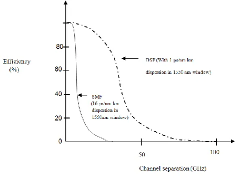
Figure 9. Efficiency of four-wave mixing with respect to channel separation
SPM and CPM are significant mainly for high bit rate systems, but the FWM effect is independent of the bit rate and is critically dependant on the channel spacing and fiber dispersion. The Figure (9) shows efficiency of four-wave mixing with respect to channel spacing for single-mode fiber and dispersion-shifted fiber. Decreasing the channel spacing increases the four-wave mixing effect and so does decreasing the dispersion.
Stimulated Brillouin Scattering: Brillouin scattering is a
nonlinear process that can occur in optical fibers at high intensity. The high intensity produces compression (due to electric field also known as pump field) in core of fiber through the process known as electrostriction. This phenomenon produces density-fluctuations in fiber medium. It increases the material disorder, which in turn modulates the linear refractive index of medium and results in an electrostrictive-nonlinearity. The modulated refractive index behaves as an index grating, which is pump- induced. The scattering of pump light through Bragg diffraction by the
[image:5.595.311.550.347.527.2]pump-induced index grating is called as Brillouin scattering (Agrawal, 1995; Shen, 1965; Buckland, 1996). The disorder is time dependent so the scattered light is shifted (Brillouin shift). Typically for an optical system at 1550 nm, the threshold power for Brillouin scattering is about 1 mW. Because of such a low value of threshold level, the SBS process is a dominant nonlinear process in fibers.
Stimulated Raman Scattering: The Raman scattering effect
is the inelastic scattering of a photon with an optical phonon, which originates from a finite response time of the third order nonlinear polarization of the material (Lan, 1981). When a monochromatic light beam propagates in an optical fiber spontaneous Raman scattering occurs. The scattered photons may lose energy (Stokes shift) or gain energy (anti-Stokes shift). If the pump beam is linearly polarized, the polarization of scattered photon may be the same (parallel scattering) or orthogonal (perpendicular scattering). If photons at other frequencies are already present then the probability of scattering to those frequencies is enhanced. This process is known as stimulated Raman scattering. In stimulated Raman scattering, a coincident photon at the downshifted frequency
will receive a gain (Bromage, 2004; Stolen et al., 1972). This
feature of Raman scattering is exploited in Raman amplifiers for signal amplification (Agrawal, 2002). For a typical optical communication system at 1550 nm, the threshold power for stimulated Raman scattering is about 570 mW. As channel powers in optical communication systems are typically below 10 mW, SRS process is not a limiting factor for single-channel lightwave systems. However it affects the performance of WDM systems considerably (Agrawal, 1995).
Future Trends
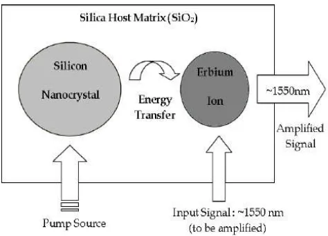
[image:6.595.46.283.531.702.2]Erbium doped fiber amplifier is an important ingredient of optical fiber communication systems. Better technologies have to be developed to increase the performance and capability of EDFAs. For removing main disadvantages there are some proposals. One of the important ideas is using nanotechnology for improving amplification process as shown in Figure (10).
Figure 10. Schematic diagram of Si-Nanocrystal Erbium-doped fiber amplifier
It was shown that by adding silicon nanocrystals to Er-doped
SiO2 the absorption cross-section is strongly enhanced
(Pacifici, 2003; Yu et al., 2006). Also, it was shown that
doping of nanocrystals into fiber causes the excitations of Er-ions, compared to traditional EDFA, through a strong coupling
mechanism. This energy transfer process could enable the fabrication of an optical amplifier operating at 1550 nm that is
optically excited at pump intensities as low as a few mW/cm2.
The addition of Si-nanocrytals into Er-doped optical fiber may decrease fiber length for given gain and therefore reduced nonlinear impairments. Polymer optical fibers offer many benefits as compared to other data communication solutions such as copper cables, wireless communication systems, and glass fibers. Polymer optical fibers provide an easy and less expensive processing of optical signals, and are more flexible for plug interconnections in comparison to glass optical fibers
(Fischer et al., 2011). The use of polymer optical fibers as the
transmission media for aircrafts is presently under research by different research and development groups due to its benefits. Presently, traditional optical networks are not able to adapt the rapid growth of online data services due to the unpredictability of dynamic allocation of bandwidth. Traditional optical networks rely mainly on manual configuration of network connectivity, which is time consuming, and unable to fully adapt the demands of the modern network. Intelligent optical network is a future trend in optical network development, and will have applications in areas like traffic engineering, dynamic resource route allocation, special control protocols for network management, and bandwidth on demand (Wang, 2004; Idachaba, 2014). A dedicated hardware configuration working in the optical domain and use of ultra-fast photonic sections is expected to further improve the capacity and speed
of telecommunication networks (Colin Yao, 2013;
Khodakarami, 20146). As optical networks become more complex in the future, the use of optical laser neural nodes can be an effective solution.
Conclusion
The evolutionary trends in fiber optic systems are discussed. The multichannel transmission at 1550 nm window for high bandwidth and long haul light wave systems reached to state of art situation. Soliton based optical fiber communication systems are very promising. They are more suitable for high capacity trans-oceanic communication. These systems are still to be developed for field applications. By using soliton based optical switches multi GBPS data rate can be achieved for optical computation. Intelligent optical transmission networks, laser neural networks and nanotechnology in optical amplification will further improve the optical communication systems. All optical communication systems working in optical domain are expected in future. Such systems will definitely lead optical communication to a new era.\
Acknowledgement
Author is thankful to Prof. Nar Singh, J. K. Institute of Applied Physics, University of Allahabad for giving permission to use the facilities over there. Author dedicates this paper to year 2015, the International Year of Light and Light-based Technologies as declared by United Nations.
REFERENCES
Agrawal, G. P. 1995. “Nonlinear Fiber Optics” 2nd
Ed.,Acadenic Press.
Agrawal, G. P. 2002. “Fiber-Optic Communication Systems,”
Basch, E. E., Beaudette, R.A. and Carner, H.A. 1978. “Optical transmission for inter office trunks,” IEEE Trans. Commun., Vol. 26, pp. 1007-1014, July.
Bromage, J. 2004. “Raman amplification for fiber
communication systems,” J. Lightwave Technol., Vol. 22, No. 1, pp. 79-93.
Buckland, E. L. & Boyd, R. W. 1996. “Electrostrictive contribution to the intensity-dependent refractive index of optical fiber,” Opt. Lett. 21, pp. 1117-1119.
Chraplyvy, A. R. 1990. “Limitations on lightwave communications imposed by optical fiber nonlinearities,” J. Lightwave Technol., Vol. 8, pp. 1548–1557.
Clesca, B. et al. 1994.“Gain flatness comparison between
erbium-doped fluoride and silica fiber amplifiers with wavelength-multiplexed signals,” IEEE Photon. Technol. Lett., Vol. 6, No. 4, pp. 509- 512.
Colin Yao, 2013. “The future of fiber optic communication”, available at: www.streetdirectory.com.
Daikoku, M., Yoshikane, N., Otani, T. and Tanaka, H. 2006. “Optical 40-Gb/s 3R regenerator with a combination of the
SPM and XPM effects for all-optical networks,” J.
Lightwave Technol., Vol. 24, No. 3, pp. 1142–1148.
Desurvire, E. 1994. “Erbium-Doped Frber Amplifiers,” Wiley, NewYork.
Fischer, U.H.P., Haupt, M. and Janoic, M. 2011. “Optical transmission systems using polymeric fibers”, Available at: http://www.intechopen.com/books.
Franz, J. H. and Jain, V. K. 2000. “Optical Communications: Components and System,” Narosa Publishing House, New Delhi.
Gangwar, R., Singh, S. P. and Singh, N. 2007. “Soliton based optical communication,” Progress In Electromagnetics Research, PIER 74, pp. 157-166.
Giles, C. R., Desusvire, E. 1991. “Modelling erbium-doped fiber amplifiers,” J. Lightwave Technol., Vol. 9, No. 2, pp. 271-283.
Haus, H. A. 1993. “Optical fiber solitons: their properties and uses,” Proc. IEEE, Vol. 81, pp. 970-983.
Idachaba, F., Ike, D.U. and Hope, O. 2014. “Future trends in fiber optics communication,” Proc. World Congress on Engineering (WCE 2014), London, UK, Vol. 1.
Islam, M. N. 2002. “Raman amplifiers for
telecommunications,” IEEE J. Selected Topics in Quantum Electron., Vol. 8, No.3, pp. 548-559.
Keiser, G. 2000. “Optical Fiber Communications,” 3rd Ed.,
Mc-Graw Hill.
Khodakarami, H., Pillai, B. S. G., Sedighi, B. and Shieh, W. 2014. “Flexible optical networks: an energy efficiency perspective”, J. Lightwave Technol., Vol. 32, No. 21, pp. 3958-3969.
Kikuchi, N., Sekine, K. and Saski, S. 1997. “Analysis of XPM effect on WDM transmission performance,” Electron. Lett., Vol. 33, pp. 653–654.
Koenig, D. 1984. “Telegraphs and Telegrams in Revolutionary France,” Scientific Monthly, 431.
Koester, C.J. and Snitzer, E.A. 1964. “Amplification in fiber lasers,” Appl. Optics, Vol. 3, pp. 1182-1187.
Lan, G.L., Banerjee, P. K. and Mitra, S. S. 1981. “Raman scattering in optical fibers,” J. of Raman Spectroscopy, Vol. 11, pp. 416-423.
Mollenauer, L. F. and Smith, K. 1988. “Demonstration of soliton transmission over more than 4000 km in fiber with loss periodically compensated by Raman gain,”Opt. Lett. 13, pp. 675-677.
Namiki, S., Seo, K., Tsukiji, N. and Shikii, S. 2006. “Challenges of Raman amplification,” Proc. IEEE, Vol. 94, No. 5, pp. 1024-1034.
Noshada, M., Rostami, A. 2012. “FWM minimization in
WDM optical communication systems using the
asymmetrical dispersion managed fibers”, International Journal for Light and Electron Optics, Vol. 123, No. 9, pp. 758– 760.
Nusinsky, I. and Hardy, A. A. 2004. “Multichannel amplification in strongly pumped EDFAs,” J. Lightwave Technol., Vol. 22, No. 8, pp. 1946-1952.
Pacifici, D., Franzo, G., Priolo, F., Lacona, F. and Negro, L. D. 2003. “Modeling and perspective of the Si-nanocrystal erbium interaction for optical amplifier,” Phys. Review B, Vol. 67, 45301.
Pal, B. P. 1992.“Fundamentals of Fiber Optics in Telecommunication and Sensor Systems,” Wiley Eastern, New Delhi, 1992.
Payne, D. N. and Gambling, W.A. 1975. “Zero material dispersion in optical fibers,” Electron. Lett., Vol. 11, No. 8, pp. 176-178.
Potenza, M. 1996. “Optical fiber amplifiers for
telecommunication systems,” IEEE Communication Mag., Vol. 34, pp. 96-102, Oct.
Ramaswami, R. and Sivarajan, K. N. 1998.“Optical Networks-A Practical Perspective,” Morgan Kaufmann Pub., San Francisco, CA, USA.
Rkhelenko, I. D. and Kalavally, V. 2013. “Raman amplification in silica-nano crystal waveguide”, J. Lightwave Technol., Vol. 32, Iss. 1, pp. 130-134.
Rosolem, J. B. et. al. 2006. “S-C-L triple-band double-pass Er-doped silica fiber amplifier with an embedded DCF module for CWDM applications,” J. Lightwave Technol., Vol. 24, No. 10, pp. 3691-3697.
Rottwitt, K. and Stentz, A. J. 2002. “Raman Amplification in Lightwave Communication Systems,” Optical Fiber Telecommunications-IVA Component, I. P. Kaminow and T. Li, Ed., Academic Press.
Schwartz, M. I., Reenstra, W.A., Mullis, J.H. and Cook, J.S. 1978. “Chicago lightwave communications project,” Bell system Technology J., Vol. 57, pp. 1881-1888, June-Aug. Shen, Y. R. and Bloembergen, N. 1965. “Theory of stimulated
Brillouin and Raman scattering,” Phys.Rev.A137, pp. 1787-1805.
Singh, S. P., Kar, S. and Jain, V. K. 2004. “Novel strategies for reducing FWM using modified repeated unequally spaced channel allocation,” Fiber and Integrated Optics, Vol. 6, pp. 415–437.
Stolen, R. H. 2008. “The early years of fiber nonlinear optics,” J. Lightwave Technol., Vol. 26, No. 9, pp. 1021-1031. Stolen, R. H. and Lin, C. 1978. “Self-phase modulation in
silica optical fibers,” Physical Review-A, Vol. 17, No. 4, pp. 1448–1453.
Stolen, R. H., Ippen, E. P. and Tynes, A. R. 1972. “Raman oscillation in glass optical waveguide,” Appl. Phys. Lett., 20, pp. 62-64.
Sunil. P. Singh, Abhinay K. Sharma and Nar Singh, “Crosstalk reduction in WDM systems using hybrid amplification technique,” J. Optics Communication, Vol. 285, Iss. 19, pp. 3931-3934, 2012.
Wang, X. and Kitayama, K.2004. "Analysis of beat noise in coherent and incoherent time-spreading OCDMA," J. Lightwave Technol. ,Vol. 22, No. 10, pp. 2226-2235.
Welsh, T., Smith, R., Azami, H. and Chrisner, R. 1996. “The
FLAG cable system,” IEEE Communication Mag. 34(2),
pp. 30-35.
Yamada, M. and Shimizu, M. 2003. “Ultra-wideband amplification technologies for optical fiber amplifiers,” NTT Technical Review, Vol. 1, No. 3, pp.80-84.
Yu. V., Timoshenko, D., Zhigunov, M., Kashkarov, P. K., Shaligina, O. A., Tetrukov, S. A., Zhang, R. J., Fujii, Sh. Hayashi, M. 2006. “Photoluminescence properties of Er doped structure of silicon nanocrystal in silicon dioxide matrix,” Journal of Nanocrystal Solids, 352.