ISSN Online: 2327-5227 ISSN Print: 2327-5219
DOI: 10.4236/jcc.2018.67008 Jul. 31, 2018 84 Journal of Computer and Communications
Determination of Array Gain of Single
Hop to Achieve the Performance of a
2-Hop Wireless Link
Abu Sayed Md. Mostafizur Rahaman
1, Jesmin Akhter
2, Md. Rafsan Jani
1, Md. Imdadul Islam
11Department of Computer Science and Engineering, Jahangirnagar University, Savar, Dhaka, Bangladesh 2Institute of Information Technology, Jahangirnagar University, Savar, Dhaka, Bangladesh
Abstract
In adaptive beamforming system adaptive algorithm of digital filter is applied to update the weighting vector of the antenna elements to get antenna gain along the desired direction and attenuation along the jammer. The objective of the paper is to evaluate the threshold gain of the adaptive beam former along the line of sight (LOS) between the transmitter and the receiver (in-cluding jammer suppression) to make the single hop link comparable with 2-hop link. The single hop and 2-hop communication systems are compared in context of symbol error rate (SER) under fading condition theoretically and verified by simulation. Finally we evaluate the numerical value of thre-shold gain of adaptive beamformer of two antenna elements under Rayleigh and Nakagami-m fading conditions.
Keywords
Array Antenna System, BER, Threshold Array Gain, Side Lobe Canceller, Path Loss
1. Introduction
To combat the fading affect of long wireless link, 2-hop model is widely used where a relay is placed between transmitter and receiver. The concept is applica-ble to enhance the performance of point to point link. The combined SNR of two links becomes approximately parallel combination of two SNRs like equivalent parallel resistor of electrical circuit. Therefore the combined SNR is less than the individual SNR (between transmitter and repeater or repeater and receiver) but the SNR between the transmitter and receiver (without the repeater station) is
How to cite this paper: Rahaman, A.S.Md.M., Akhter, J., Jani, Md.R. and Islam, Md.I. (2018) Determination of Array Gain of Single Hop to Achieve the Perfor-mance of a 2-Hop Wireless Link. Journal of Computer and Communications, 6, 84-98.
https://doi.org/10.4236/jcc.2018.67008 Received: July 1, 2018
Accepted: July 28, 2018 Published: July 31, 2018 Copyright © 2018 by authors and Scientific Research Publishing Inc. This work is licensed under the Creative Commons Attribution International License (CC BY 4.0).
http://creativecommons.org/licenses/by/4.0/
DOI: 10.4236/jcc.2018.67008 85 Journal of Computer and Communications much less than the combined SNR of 2-hop wireless link. This phenomenon at-tracts the researcher to apply the concept of multi-hop in wireless networks to reduce SER and enhance throughput. The performance analysis of two-hop wireless link in context of BER under fading is discussed in [1] [2] [3] [4]. Usually in rural or suburban area the gain of the relay is kept constant called amplify-and-forward (AF) relaying. In a dense urban area the wireless link is found as time selective channel i.e. SNR of receiver varies with time hence the gain of the relay has to be adjusted with feedback signal like adaptive algorithm of digital filter. The concept of AF and DF relay is found in [5][6][7] where the idea of channel state information is included. In [8], authors analyzed perfor-mance of AF relay network where relay is affected by interferences under as-sumption that there is no obstacle between interferences and relay i.e. LOS in-terferences. The paper derived closed form solution of outage probability with the idea of [9][10]. To reduce BER of 3G mobile cellular destined for high speed communication needs to overcome small scale fading (Rayleigh fading). In this context selection of best relay is discussed in [11] with MIMO (multiple input multiple output). Actually MIMO is used in wireless link to take the advantage of space diversity at the expense of system cost. Different combination of MIMO (both the hop is MIMO, MISO in first hop and SIMO in second hop, SIMO in first hop and MISO in second hop etc.) is found in recent literature for 2-hop wireless link [11][12][13].
The main objective of AAS is to combine the radiation pattern of individual antenna element (with proper weighting factor and phase shift) to produce a combined beam of desired directivity and gain. The detail analysis of AAS is found in [14] [15][16]. To make the system dynamic, adaptive beam forming algorithm is used to select the appropriate weighting factor of antenna elements. Several applications of AAS for example: Beam Steering and Switching, Conven-tional Beam Forming, Diversity Combining, Array on Satellites, Dynamic beams, Reduction in Delay Spread and Multipath Fading, Reduction in Co-channel Interference etc. are discussed in [14]. The same author discussed detail about mathematical model and adaptive algorithms of conventional beam former, null-steering beam former, optimal beam forming, broad-band beam forming, frequency-domain beam forming, SMI algorithm, LMS algorithm, RLS algorithm, MVDR estimator etc in [15]. In this paper we make a comparison of 2-hop wireless link under single antenna system with the case of direct wireless link (without relay) of array antenna system (AAS) to reduce complexity of communication system. Two most important features of 5G mobile communi-cation are: “Ultra-Dense Networks (UDN)” and “massive MIMO” hence mul-ti-hop wireless link will make the system very complex. The objective of the pa-per is to acquire the capacity of single hop link equivalent to dual hop link. The adaptive beamformer can only help us to achieve the goal.
DOI: 10.4236/jcc.2018.67008 86 Journal of Computer and Communications concept of AAS, overall SINR (signal to interference and noise ratio) at receiving end and algorithms of adaptive beamforming; Section 4 provides the results based on theoretical analysis of Section 3; and Section 5 concludes the entire analysis.
2. Dual-Hop Wireless Link
First of all we consider the 2-hop wireless link of Figure 1 where the SNR be-tween transmitter and relay is ΓSR and that of relay to destination is ΓRD.
The received signal vector at the relay is expressed as:
R= E SR + SR
y H x n , (1) where E is the transmitted power, HSR is the channel matrix from the source to relay, x is the signal vector of source, and nSR is the noise vector of source to relay link. Above expression is applicable for MIMO system but for single an-tenna system instead of signal vector we consider individual symbol (for exam-ple symbols of 16-QAM) of transmitter and instead of channel matrix we con-sider simply channel gain may be complex number. When the signal is detected at relay, it is processed and transmitted with some delay expressed as: yRD′ hence the received signal vector at the destination is,
D= E RD RD′ + RD
y H y n (2) The noise vector on both the links are uncorrelated and possesses the proper-ties:
(
†)
0 R
SR SR N
n n I N
Ε = and
(
†)
0 D
RD RD N
n n I N
Ε = , where N0 is the variance of the additive white Gaussian noise (AWGN), INR is the identity matrix with NR antennas at the relay station and ND is the number of antennas at the destina-tion.
If the SNR of the links are: Γ =SR E HS SR 2 N0 and
2 0 RD E HR RD N
Γ = ,
then the overall SNR will be [4][11]:
1
SR RD SD
SR RD
Γ Γ Γ =
Γ + Γ + (3)
This overall SNR will be compared with overall SNR of AAS with adaptive beamformer under single hop of same path length.
For single antenna case Equations (1) and (2) is written conventionally like:
R SR SR
y = Ph x n+ (4)
D RD R RD
y = Ph y′ +n (5) where each variable indicates a real or complex number instead of vector.
DOI: 10.4236/jcc.2018.67008 87 Journal of Computer and Communications Once combined SNR γ = Γc SD is evaluated then the SER under awgn is ex-pressed as [8],
( )
(
2)
s c c
P γ =aQ bγ (6)
where γc is a r.v. and the integers a and b depend on type of modulation scheme. Above analysis under fading channel is expressed as,
(
_)
( )
(
_)
0
, d
c
s c av s c c c av c
P γ =∞
∫
P γ fΓ γ γ γ (7)where fΓc
(
γ γc, c av_)
is the pdf of r.v. of small scale fading channel andγ
c av_ is the average value of the r.v. In this paper we consider only Nakagami-m fad-ing channel. For example for Nakagami-m fading case the pdf becomes,(
)
( )
2_
1 _
_
, e c c av
c
m m m c c c av m
c av
m f
m
γ γ
γ γ γ
γ
− −
Γ = Γ (8)
We can use Equations (7) and (8) to evaluate SER under Nakagami-m fading case.
3. Adaptive Beamforming
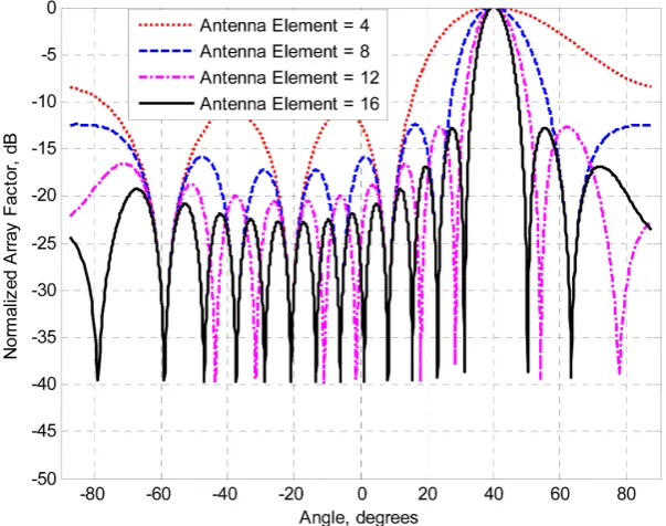
In array antenna system the number of antenna elements is a vital factor to achieve a wide variation of directivity and gain visualized from Figure 2; where a linear array is considered with spacing of antenna elements of half wavelength
i.e. λ/2.
[image:4.595.223.525.464.702.2]Extraction of the original signal from a noisy environment is achieved by Fi-nite Impulse Response (FIR) or InfiFi-nite Impulse Response (IIR) filter but their coefficients remain fixed during entire operation. In adaptive filter, adaptive
DOI: 10.4236/jcc.2018.67008 88 Journal of Computer and Communications algorithms are used to adjust the coefficients of the digital filter so that the dif-ference between the noisy input signal, Xk and the desired signal, d called the error signal ε attains at minimum value. The common algorithms found wide-spread applications are the least mean square (LMS), the recursive least squares (RLS), and the Kalman filter algorithms. In terms of computational complexity and storage requirements, the LMS algorithm is the most efficient but the Kal-man filter is suitable for immunity of any type of noise at the expense of process time. To enhance the gain of the antenna array in the direction of desired signal and to provide attenuation in the direction of interference or multiple jammer we use adaptive algorithm of IIR and FIR filter. An adaptive filter consists of FIR/IIR and adaptive algorithm to adjust the weighting factor of each branch of signal discussed in [17][18], such concept in AAS is called adaptive beamform-ing. The following two sub-sections will provide the basic concept of adaptive beamforming technique where the concept is available in [19][20].
Let us now provide the way of enhancement of gain in desired direction and elimination of jammers using the concept of adaptive beamforming. We will then determine the threshold gain of the beamformer under a single hop wire-less link to be comparable with case of 2-hop link in context of SER. In adaptive beam former two types of omni antennas are used 1) primary antenna 2) refer-ence antenna. Both types of antennas receive signal and interferrefer-ence/jammer. Each reference antenna element is associated with adaptive filter and its weight is adjusted in such a way that it can receive only jammer where the primary an-tenna provides the sum of signal and jammer. Now the jammer part of the pri-mary antenna is correlated with the output of reference antenna hence the error between primary and reference antenna provides the required signal component. The weighting factors of reference antenna elements are updated using adaptive algorithms of [21].
To match with multiple jammers of different direction at the same time, it is necessary to have more than one reference omni as explained in [22][23]. Fig-ure 3 shows the arrangement of such antenna system considering two spatially separated reference omnis.
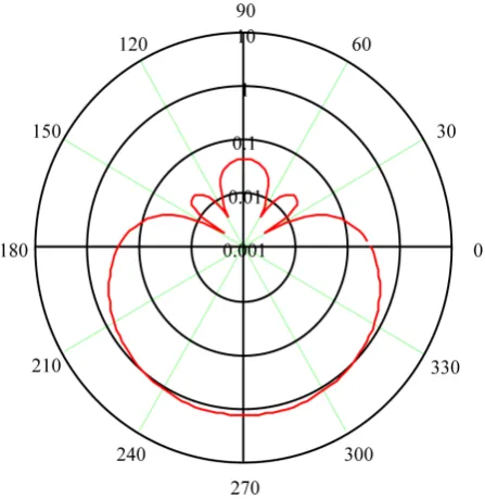
Radiation pattern of two reference adaptive beamforming is shown in Figure 4 taking the weighting factors as: w11= −0.48, w12= −0.871, w21=1.7 and
22 1
w = based on [24]. Here the null forms along 30˚, 150˚, 60˚ and 120˚; where
the main beam is directed along 270˚.
The overall SINR at receiving end is, 0
0 1
r d k
j j j
P G G
I A N
=
⋅
Γ = ≈ Γ ⋅
⋅ +
∑
(9)DOI: 10.4236/jcc.2018.67008 89 Journal of Computer and Communications
Figure 3. Side lobe canceller with two incident signals.
Figure 4. Radiation pattern of two reference antenna system.
In free space path loss model the received signal at a distance d is expressed as:
r t
P K P d= ⋅ ⋅ −α; where α is path-loss exponent. Therefore if the distance is
in-creased to twice of the previous one then the received signal or SNR is dein-creased by a factor of 2−α. The overall SNR of 2-hop wireless link (distance of each is d) is
approximately half of SNR of single hop link of distance d. If the enhancement of overall gain G of the array antenna system is greater than 2−α-1then the
DOI: 10.4236/jcc.2018.67008 90 Journal of Computer and Communications
3.1. Algorithm-1
In this algorithm we use the concept of Wiener filter theory in minimization of mean square error of cost function which actually represents the difference be-tween output of the adaptive filter and desired output. For input signal u(n) and
kth weighting factor Wk the output signal from a linear combiner is given as,
( )
1 *(
)
0 M
k k
y n −W u n k
=
=
∑
− (10)Output power,
( )
2 1 1 *(
) (
)
1 1 *(
)
0 0 0 0
M M M M
k i k i
k i k i
P y n − −W W E u n k u n i − −W W r i k
= = = =
= =
∑ ∑
− − =∑ ∑
− (11)where E u n k u n i
(
−) (
−)
=r i k(
−)
is the autocorrelation function. If the beamformer is subjected to a linear constraint, 1 * 00 e M
j k k
k W g
θ
− −
=
=
∑
; thenthe real valued cost function becomes,
(
)
01 1 1
* * *
0 0 Re 0 e
M M M
j k
k i k
k i k
J − −W W r i k λ −W −θ g
= = =
= − + −
∑ ∑
∑
(12)where g is the complex-valued gain, θ0 desired electrical angle of arrival.
Taking gradient of J and putting the result equal to zero like Wiener filter theorem, we get the optimum weighting vector like,
( )
( )
( )
* 1 0 0 1 0 0 H g R S WS R S
θ
θ θ
− −
= (13)
where
( )
0 20 ( 1)00 1 e j e j e j M
S θ −θ − θ − −θ
= is known as steering vector
and its details are found in [27][28][29].
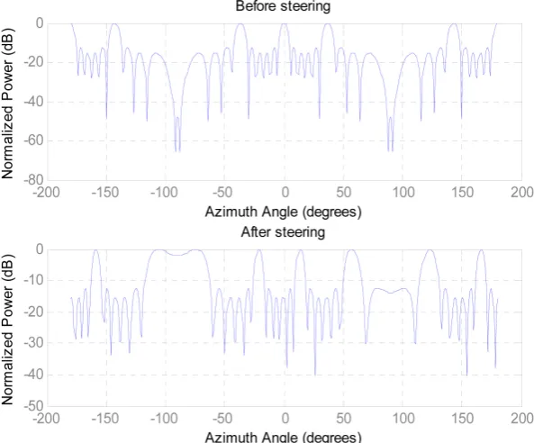
Considering uniform linear array of N = 6 antenna elements the variation of normalized power (dB) against the azimuth angle is shown in Figure 3 taking the AOA of: azimuth 60˚, elevation 15˚ and carrier frequency of fc = 1 GHz. The response is found different after inclusion of steering vector, visualized the Fig-ure 5.
The steering vector corresponding to Figure 5 is,
[
]
T0.9971 0.0760 0.8350 0.5503 0.3234 0.9462
0.3234 0.9462 0.8350 0.5503 0.9971 0.0760
i i i
i i i
= − − − − +
− − + − +
S
3.2. Algorithm-2
DOI: 10.4236/jcc.2018.67008 91 Journal of Computer and Communications
Figure 5. The profile of normalized power against azimuth angle.
Figure 6. Adaptive beamformer with LCMV.
Winner filter theorem is applied to in getting weighting vector for minimum output y(n).
Let us introduce multiple linear constraints by the constraint matrix C and gain vector g like,
H =
C W g (14) where the overall weight vector is, W W C W= q− a a
The desired signal of the beamformer,
( )
H( )
q
d n =W U⋅ n ; where
(
H)
1 q−
=
W C C C g (15)
If Ca is a stop band FIR filter with zero response in desired direction θ0 then the signal with sidelobe is H
( ) ( )
a n =x n
C U and the output signal is
( )
( )
H( )
.q y n =d n −W x n
Applying Winner filter theorem,
(
H)
1 Ha a a a q
−
=
W C RC C RW (16)
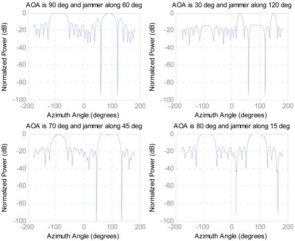
[image:8.595.255.490.354.455.2]DOI: 10.4236/jcc.2018.67008 92 Journal of Computer and Communications Taking the following parameters under LCMV: SNR = 50 dB, carrier fre-quency fc = 1 GHz, the number of antenna elements N = 10, antenna spacing λ/2 and elevation angles 0˚ we get the following response (using simulation of LCMV in Matlab 13) for different AOA and directions of jammer (azimuth an-gle) shown in Figure 7. Such concept is available for both linear and circular ar-ray in [30].
The weighting vectors for above 4 cases are evaluated as:
[
]
1
T
0.0489 0.1267 0.0443 0.1161 0.0540 0.0985 0.0322 0.0688
0.0176 0.1005 0.0264 0.0665 0.0128 0.0669 0.0613 0.1043
0.0407 0.1328 0.0558 0.1188
W i i i i
i i i i
i i = − − + − − + − − − + − − + − − +
[
]
2 T0.0680 0.0776 0.0364 0.0809 0.0568 0.0648 0.0782 0.0738
0.0767 0.0872 0.0847 0.0737 0.0767 0.0672 0.0731 0.0556
0.0619 0.0593 0.0786 0.0830
W i i i i
i i i i
i i = − + − + − − − + − + − − − +
[
]
3 T0.0452 0.0686 0.0665 0.0640 0.0487 0.0840 0.0318 0.0945
0.0142 0.1566 0.0035 0.1070 0.0446 0.0866 0.0445 0.0989
0.0491 0.0701 0.0633 0.0493
W i i i i
i i i i
i i = − − + − − + − − + − − + − − +
[
]
4 T0.0009 0.0962 0.0208 0.0956 0.0021 0.1051 0.0014 0.0879
0.0004 0.1425 0.0111 0.0963 0.0161 0.0788 0.0055 0.1134
0.0096 0.1043 0.0049 0.0833
W i i i i
i i i i
i i
= − − − + − − +
− − − + − − − +
− − +
4. Results
[image:9.595.228.520.454.692.2]In this paper the matric used against the performance of wireless link is SER or
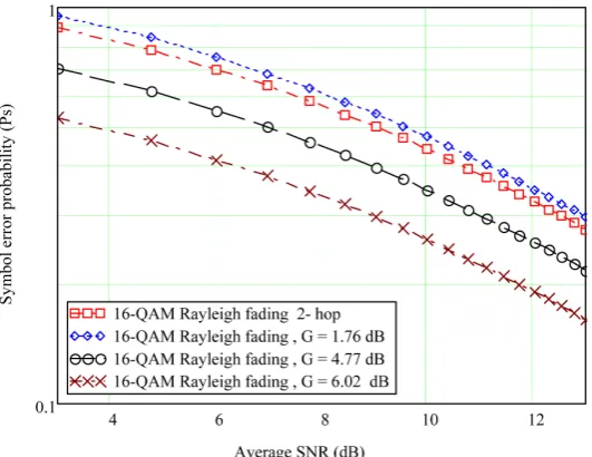
DOI: 10.4236/jcc.2018.67008 93 Journal of Computer and Communications BER for single and 2-hop cases. Figure 8 shows the profile of SER against aver-age SNR for both 2-hop link and single hop link of same path length incorpo-rating AAS of two antenna elements. Here our proposal becomes successful when overall gain (enhancement of desired signal and attenuation of interfe-rences) G is greater than or equal to 3.44 dB for Nakagami-m fading with m = 4. In Figure 8 we found that SER of single hop is better than the case of 2-hop for
[image:10.595.240.507.234.440.2]G = 4.77 and 6.02 dB but worse than it for G = 3.42 dB. In case of Rayleigh fad-ing the threshold gain G becomes 1.86 visualized from Figure 9 where the SER is found better than 2-hop for G = 1.76, 4.77 and 6.02 dB but worse than it for G = 1.76 dB.
Figure 8. The comparison of SER under 2-hop link and single link with AAS for Nakagami-m fading.
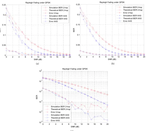
[image:10.595.242.508.486.691.2]DOI: 10.4236/jcc.2018.67008 94 Journal of Computer and Communications Finally we compare the theoretical and simulation results regarding 2-hop and single hop AAS under QPSK modulation scheme. We use Rayleigh and Naka-gami-m fading condition with bit rate of 9.6 Kbps and Doppler shift of 100 Hz. First the simulation is done for 2000 random symbols shown in Figure 10(a)
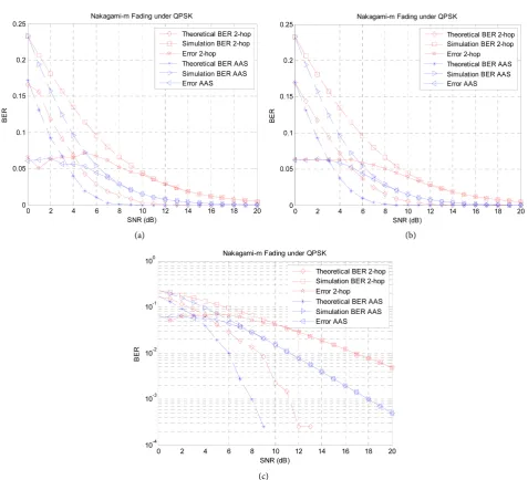
then for 200,000 symbols shown in Figure 10(b). The simulation curves become smothering for more symbols validates the concept Monte Carlo simulation. The similar result is shown in logarithmic scale in Figure 10(c). The difference be-tween simulation and theoretical result is less than 5% hence ensure 95% confi-dence level. All the curves reveal the success of our proposed scheme when we use G = 1.86 under the simulation as well. Similar job is done for Nakagami-m
fading case shown in Figures 11(a)-(c).
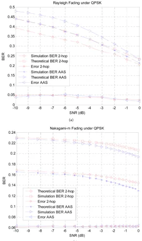
[image:11.595.63.538.277.700.2]The relative performance between Rayleigh and Nakagami-m is found subtle for SNR in the range of 0 dB to 20 dB. To observe the variation we plot BER
DOI: 10.4236/jcc.2018.67008 95 Journal of Computer and Communications
Figure 11. Comparison of 2-hop and AAS with simulation for Nakagami-m fading case.
against SNR in the range of −10 dB to 0 dB shown in Figure 12(a) and Figure 12(b); where the performance under Nakagami-m fading is found better than that of Rayleigh case because of strong link between transmitter and receiver for former case. Finally the performance of AAS is found better than conventional 2-hop wireless link for SNR in the range of 0 dB to 20 dB visualized from Figure 10 and Figure 11. Situation is found reverse for SNR in the range of −10 dB to 0 dB shown in Figure 12(a) and Figure 12(b) taking the same overall array gain. To overcome the above cumbersome situation the array gain has to be changed at low SNR condition even we have to consider the environment of fading.
5. Conclusion
DOI: 10.4236/jcc.2018.67008 96 Journal of Computer and Communications
Figure 12. Comparison of 2-hop link and AAS at low SNR.
DOI: 10.4236/jcc.2018.67008 97 Journal of Computer and Communications
Conflicts of Interest
The authors declare no conflicts of interest regarding the publication of this pa-per.
References
[1] Mohammadreza, B. and Umit A. (2017) BER Analysis of Dual-Hop Relaying Sys-tem with Energy Harvesting in Nakagami-m Fading Channel. 2017 Advances in Wireless and Optical Communications, Riga, Latvia, 96-101.
[2] Bin, L. and Yue, R. (2017) Joint Source and Relay Design for Wireless Powered AF MIMO Relay Systems with Direct Link. 2017 IEEE Globecom Workshops (GC Wkshps), Singapore, 1-6.
[3] Fawaz, S., Caijun, Z., Khalid, A., Hussein, A. and Tharm, R. (2011) Performance Analysis of Fixed-Gain AF Dual-Hop Relaying Systems over Nakagami-m Fading Channels in the Presence of Interference. EURASIP Journal on Wireless Commu-nications and Networking, 2011, 1-10.
[4] Afsana, N., Chowdhuray, A., Imdadul, I. and Amin, M. (2013) Performance Evalua-tion of Two-Hop Wireless Link under Nakagami-m Fading. International Journal of Advanced Computer Science and Applications (IJACSA), 4, 142-146.
[5] Shubha, S., Madhukumar, A. and Swaminathan, R. (2018) Switching-Based Hybrid FSO/RF Transmission for DF Relaying System. 2018 IEEE Wireless Communica-tions and Networking Conference (WCNC), Barcelona,15-18 April 2018, 1-6. [6] Huang, S., Chen, H. and Zhang, Y. (2012) Optimal Power Allocation for Spectrum
Sensing and Data Transmission in Cognitive Relay Networks. IEEE Wireless Communications Letters, 1, 26-29.
https://doi.org/10.1109/WCL.2012.120211.110056
[7] Huogen, Y., Tang, W. and Li, S. (2013) Outage Probability and SER of Ampli-fy-and-Forward Cognitive Relay Networks. IEEE Wireless Communications Letters, 2, 219-222.https://doi.org/10.1109/WCL.2013.012513.120834
[8] Nuwan, F. and Rajatheva, N. (2013) Effects of Line of Sight Interference on Perfor-mance of Amply-and-Forward Relay Network. IEEE Communications Letters, 17, 940-943.https://doi.org/10.1109/LCOMM.2013.040913.130328
[9] Krikidis, I., Thompson, J., Mclaughlin, S. and Goertz, N. (2009) Max-Min Relay Se-lection for Legacy Amply-and-Forward Systems with Interference. IEEE Transac-tions on Wireless CommunicaTransac-tions, 8, 3016-3027.
https://doi.org/10.1109/TWC.2009.080383
[10] Suraweera, H., Garg, H. and Nallanathan, A. (2010) Performance Analysis of Two Hop Amplify-and-Forward Systems with Interference at the Relay. IEEE Commu-nications Letters, 14, 692-694.https://doi.org/10.1109/LCOMM.2010.08.100109 [11] Ahasanun, N., Qinghai, Y. and Kyung-sup, K. (2011) Performance Analysis of
Two-Hop Cooperative MIMO Transmission with Best Relay Selection in Rayleigh Fading Channel. The International Arab Journal of Information Technology, 8, 9-15.
[12] Zhuo, C., Jinhong, Y. and Branka, V. (2005) Analysis of Transmit Antenna Selec-tion/Maximal-Ratio Combining in Rayleigh Fading Channels. IEEE Transactions on Vehicular Technology, 54, 1312-1321.https://doi.org/10.1109/TVT.2005.851319 [13] Nan, Y., Phee, L., Maged, E., Robert, S. and Iain, B. (2013) Transmit Antenna
DOI: 10.4236/jcc.2018.67008 98 Journal of Computer and Communications [14] Godara, L. (1997) Application of Antenna Arrays to Mobile Communication, Part I: Performance Improvement, Feasibility and System Considerations. Proceedings of the IEEE, 85, 1033-1060.
[15] Godara, L. (1997) Application of Antenna Arrays to Mobile Communication, Part II: Beamforming and Direction of Arrival Consideration. Proceedings of the IEEE, 85, 1195-1245. https://doi.org/10.1109/5.622504
[16] Rappaport, T. (1991) Wireless Personal Communications: Trends and Challenges. IEEE Antennas and Propagation Magazine, 33, 19-29.
https://doi.org/10.1109/74.97946
[17] Freweyni, K., Tawatu, A. and Dilip, M. (2013) Smart Antenna Techniques for In-terference Suppression in WCDMA Using LMS Algorithm. International Journal of Computing Science and Communication Technologies, 6, 916-922.
[18] Rana, L., Anum, A., Anis, R., Shahid, A. and Shahzad, A. (2011) Adaptive Beam-forming Algorithms for Anti-Jamming. International Journal of Signal Processing, Image Processing and Pattern Recognition, 4, 95-105.
[19] Feng, S. and Jinyang, S. (2015) A Robust Adaptive Beamformer Based on Semidefi-nite Programming with Quadratic Constraints. International Journal of Hybrid In-formation Technology, 8, 345-354.https://doi.org/10.14257/ijhit.2015.8.2.32 [20] Somnath, P., Abhisek, P., Nisha, N., Sujeet, K., Vikky, J. and Monoj, K. (2015)
Pow-er PattPow-ern Synthesis of Smart Antenna Array Using DiffPow-erent Adaptive Algorithms. International Journal of Advanced Research, 3, 1459-1466.
[21] Emmanuel, C. and Barrie, W. (2004) Digital Signal Processing: A Practical Ap-proach. 2nd Edition, Pearson Education, London.
[22] Widrow, B. and Samuel, D. (2005) Adaptive Signal Processing. Pearson Education, London.
[23] Haque, S., Ariful, M., Imdadul, I. and Amin, M. (2007) Radiation Pattern and Beamwidth Control of Linear and Rectangular Array Antenna System. Proceedings of the East West University Journal, 1, 119-128.
[24] Jahan, J., Imdadul, I. and Mostafizur, R. (2015) Adaptive Beamforming and Cancel-lation of Jammer Using Linear Array Antenna System. International Journal of En-gineering Sciences & Research Technology, 4, 648-657.
[25] Chiu, C., Chen, C.-H., Liao, S.-H. and Chen, K.-C. (2012) Bit Error Rate Reduction by Smart UWB Antenna Array in Indoor Wireless Communication. Journal of Ap-plied Science and Engineering,15, 139-148.
[26] Rim, H. (2013) BER Performance of Antenna Array-Based Receiver Using Mul-ti-User Detection in a Multipath Channel. International Journal of Wireless & Mo-bile Networks, 5, 94-102.
[27] Feng, S., Fengfeng, C. and Jinyang, S. (2015) Robust Adaptive Beamforming Based on Steering Vector Estimation and Covariance Matrix Reconstruction. Communi-cations Letters, 19, 1636-1639.
[28] Simon, H. (2013) Adaptive Filter Theory. 5th Edition, Prentice Hall, Upper Saddle River.
[29] Xiaojun, M., Wenxing, L., Yingsong, L., Yaxiu, S. and Zhuqun, Z. (2015) Robust Adaptive Beamforming against Signal Steering Vector Mismatch and Jammer Mo-tion. International Journal of Antennas and Propagation, 2015, Article ID: 780296. [30] Ahmed, M., Osama, M., Ghandour, F. and Hesham, F. (2015) Performance
En-hancement for Adaptive Beam-Forming Application Based Hybrid PSOGSA Algo-rithm. Journal of Electromagnetic Analysis and Applications, 7, 126-133.