© 2019, IRJET | Impact Factor value: 7.211 | ISO 9001:2008 Certified Journal
| Page 7584
Design, Analysis & Weight Reduction of Shell of Refrigerator
Compressor
Mr. Nadim Sajid Tamboli
1, Prof. A. S. Darur
21
M. Tech. (CAD-CAM-CAE) Department of Mechanical Engineering, KITCOEK, Kolhapur, Maharashtra, India.
2
Professor, Department of Mechanical Engineering, KITCOEK, Kolhapur, Maharashtra, India
---***---Abstract - The refrigerator is a device used for cooling purpose. It is one of the home appliances using mechanical vapour compression cycle in its process. Performance of the systems become the main issue and many researches are still ongoing to evaluate and improve the efficiency of any
used system.Refrigerator consist of various important part
such as, compressor, condenser and evaporator. These all components play main role in efficiency of refrigerator. If such components are having the heavy system then it may decrease the overall efficiency of refrigerator as they consume the more amount of power. Hence in this project we are working on the shell and piston of compressor in refrigerator. As we known that the compressor used in refrigerator is a reciprocating type. Connecting rod is the intermediate link between the piston and the crank shaft. And is responsible to transmit the push and pull from the piston pin to crank pin, thus converting the reciprocating motion of the piston to rotary motion of the crank. The loads acting on this piston and crank shaft are cyclic in nature. Further in this project we will use the modelling and analysis software and ensure the weight reduction and optimisation of system. The modelling software is CATIA and analysis software is ANSYS.
Key Words: Optimisation, Pressure vessel,
Compressor, Efficiency, Piston
1. INTRODUCTION
The refrigerator is used for cooling purpose. The domestic refrigerator contains the sealed compressor. This compressor is sealed because to avoid the noise. It also consists of crank shaft, connecting rod, piston, etc. In this project the optimization of piston and compressor shell will be done. This will decrease the overall weight of the system and also increase the efficiency of the system. Due to the low weight of system like Shell, piston and crank shaft the power consumption of system will be decrease and it will conclude on the increase in the efficiency of the system. This project is unique and very less work is being done on refrigerator compressor.
1.1 Technical Specifications of compressor shell used for study
Thus, Specification of the compressor shell are tabulated below:
Sr.
No. Parameter Values
1 Diameters
ID
OD
140 mm
148 mm
2 Length of Pressure vessel 190 mm
3 Internal Pressure 247 Psi
4 Thickness 4 mm
Material Specifications of MS
5 Tensile Strength, Yield 590 Mpa
[image:1.595.306.563.205.464.2]6 Force 8 kg
Table 1.1 – Specifications of existing shell
Fig. 1.1 – Photographic view of existing shell
2. LITERATURE REVIEW
[image:1.595.357.519.475.693.2]© 2019, IRJET | Impact Factor value: 7.211 | ISO 9001:2008 Certified Journal
| Page 7585
investigate and analyse the stress distribution of piston at actual engine condition. This research work suggests a new type of SiC reinforced ZrB2 composite material that can sustain at higher temperature (1680 K) and pressure (18 MPa).
[2] Jatender Datta, Dr. Sahib Sartaj Singh et al The paper shows the behavior of piston made of Carbon Graphite and Aluminum Alloy 2618 applied heat power value of 200 Watt. The result of Temperature distribution and resultant temperature gradient was found and the main motive is to find the comparison between both of materials of piston.
[3] K Ramesh Babu, G Guru Mahesh and G Harinath Gowd et al In this paper the authors have studied the variation of Isotherms and heat flux with respect to radius, height of piston, liner, cylinder head and thermal analysis. First thermal analysis was done and analyzed the temperature distribution over the convectional engine and copper coated convectional engine. In the second stage structural analysis was carried out using the thermal loads obtained in the first stage. Three different types of materials were taken for analysis.
[4] Dilip Kumar Sonar, Madhura Chattopadhyay et al The authors had studied a piston which is designed using CATIA V5R20 software. Complete design is imported to ANSYS 14.5 software then analysis is performed. Aluminium alloy has been selected for structural and thermal analysis of piston. Results are shown and a comparison is made to find the most suited design.
3. PROBLEM DEFINITION AND METHODOLOGY
A. Problem Definition
We have to reduce the overall weight of the system. The load bearing components like piston and crank shaft are used in refrigerations and are also heavy in assembly. The Shell of the compressor is also heavy. This heavy component decreases the overall efficiency. Due to the heavy weight components the power consumption of system increases and thus it is not good as it increases the running cost of the system. The material requirement also increases as the component is heavy. Hence to overcome all this problem this system should be redesign for optimisation.
B. Objectives
1. To study the current system in detail with its specification and all required considerations.
2. To design & optimize the existing material for compressor shell and piston.
3. To optimize system according to one of the following: a) Changing dimensions of system and keeping material same as it is.
b) Keeping same dimensions and changing material of components.
c) Changing both material as well as dimensions of component.
4. Modelling of new design with help of CATIA software. 5. To analyse the optimized components to study the
stress on the system.
6. To compare existing & optimized piston & shell of compressor.
C. Methodology
The following are important steps for completion of objectives -
1. Check design of various existing components in compressor.
2. Creating geometric model and finite element model of existing components of compressor using CATIA software.
3. Analysis of shell of compressor and piston by using ANSYS software.
4. Simulations for Model Analysis.
5. Optimization of compressor assembly for weight reduction.
6. Comparison between existing and optimized design.
4. DESIGN & ANALYSIS OF EXISTING COMPRESSOR SHELL
In compressor the shell carries the whole system in it. It consists the motor, cylinder, piston and other required components. The motor, piston cylinder arrangement is mounted on a spring and bolt arrangement. The weight of this system is nearly 8 Kg.
After considering the factor of safety as 2.5 the load on pressure vessel will be
8 × 2.5 = 20 Kg
Thus converting 20 Kg in Force, we get, 20 × 9.81 = 196.2 N
Material - MS
For given material we have to select standard properties of that material, such as
Syt= 590 Mpa ρ= 7860 kg/m3
Considering uniformly distributed load & FOS as 2.5 We have to calculate actual FOS for pressure vessel. Allowable Stress (σall) = Syt / Fs
= 590/2.5 = 236 Mpa.
Thus, the load acting on the shell is at its bottom plate, and other outer surface is used only for preventing the noise of the Compressor. Thus, this load acting on the system after considering factor of safety is 20 Kg, after converting it into the Force we get the Force of 197 N. Thus, the shell will be designed according to this force.
© 2019, IRJET | Impact Factor value: 7.211 | ISO 9001:2008 Certified Journal
| Page 7586
Mmax = (P/4 × ∏) × (1 + µ) ln (r/R)
= (197/ 4 × ∏) × (1+0.3) ln (74/20.5) = 26.16 N-mm
σ = (6M) / t 2
= (6 × 26.16) / 4 2
= 9.81 Mpa
Thus, of we compare this stress with allowable then it is very less. Thus, the Optimization can be achieved in the system.
Deflection on the Shell is given as follows δ = 0.217 × F × r2 / E × t3
= 0.217 × 197 × 744 / 2.1 × 105 × 43
= 0.017 mm
[image:3.595.310.560.258.382.2]The there is scope for geometric optimization if we Compare the Stress.
Fig. 4.1 – Geometric model of shell
Fig. 4.2 – Meshing of shell
[image:3.595.67.258.281.433.2]Fig. 4.3 – Boundary conditions for shell
[image:3.595.68.255.283.610.2]Fig. 4.4 – Stress analysis of shell
Fig. 4.5 Deformation analysis of shell
5. DESIGN & ANALYSIS OF OPTIMIZED SHELL
In compressor the shell carries the whole system in it. It consists the motor, cylinder, piston and other required components. The motor, cylinder piston arrangement is mounted on a spring and bolt arrangement. Weight of this system is nearly 8 Kg. After considering the factor of safety as 2.5 the load on pressure vessel will be
8 × 2.5 = 20 Kg
[image:3.595.305.562.408.536.2]© 2019, IRJET | Impact Factor value: 7.211 | ISO 9001:2008 Certified Journal
| Page 7587
Case 1) Changing dimensions of system and keeping material same as it is:
In this case the dimensions of the system are changed by iterative method and material is kept same as that of existing system.
Consider factor of safety as 2.5, Material - MS
For given material we have to select standard properties of that material, such as
E= 2.10×10⁵ Mpa
Syt= 590 Mpa ρ= 7860 kg/m3
Considering uniformly distributed load & FOS as 2.5 We have to calculate actual FOS for shell.
Allowable Stress (σall) = Syt / Fs = 590/2.5 = 236 Mpa.
Thus, the load acting on the shell is at its bottom plate, and other outer surface is used only for preventing the noise of the Compressor. Thus, this load acting on the system after considering factor of safety is 20 Kg, after converting it into the Force we get the Force of 197 N. Thus, the shell will be designed according to this force.
Sample iteration
Outer Diameter = 148 mm Inner Diameter = 140 mm Thickness 4 mm
Considering the force is exerted in the circular plate at bottom of compressor, we get the stress as follows Mmax = (P/4 × ∏) × (1 + µ) ln (r/R)
= (197/ 4 × ∏) × (1+0.3) ln (74/20.5) = 26.16 N-mm
σ = (6M) / t 2
= (6 × 26.16) / 4 2
= 9.81 Mpa
Thus, of we compare this stress with allowable then it is very less. Thus, the Optimization can be achieved in the system.
Deflection on the Shell is given as follows, δ = 0.217 × F × r2 / E × t3
= 0.217 × 197 × 744 / 2.1 × 105 × 43
= 0.017 mm
Same like this, 12 such iterations are carried on. The following table shows the iterations
Thick Inner Outer Stress Final Weight Difference
4 140 148 9.8 4.74 0.00
3.5 141 148 12.8 4.17 0.57
3 142 148 17.4 3.59 1.15
2.5 143 148 25.0 3.01 1.73
2 144 148 39.1 2.42 2.32
1 146 148 156.3 1.22 3.52
4 137 145 9.6 4.60 0.14
3.5 138 145 12.6 4.05 0.69
3 139 145 17.1 3.49 1.25
2.5 140 145 24.6 2.92 1.82
2 141 145 38.5 2.35 2.39
[image:4.595.305.562.70.194.2]1 143 145 153.8 1.19 3.55
Table 5.1 - Iteration Table for changing dimensions & keeping same material
Case 2) Keeping same dimensions and changing material of components:
In this case the dimensions of existing systems are kept as it is and material and its properties are changed. While selecting these three materials the availability, cost and required strengths are checked. The three materials used in this system are as follows:
1. A 36 hot rolled
2. Stainless steel 304
3. Aluminium alloys
Iteration (1):
Material – A 36 (Hot rolled)
For given material we have to select standard properties of that material, such as
E= 2×10⁵ Mpa
Syt= 400 Mpa ρ= 7800 kg/m3
Considering uniformly distributed load & FOS as 2.5 We have to calculate actual FOS for optimised roller. Allowable Stress (σall) = Syt / Fs
= 590/2.5 = 236 Mpa.
Considering the force is exerted in the circular plate at bottom of compressor, we get the stress as follows Mmax = (P/4 × ∏) × (1 + µ) ln (r/R)
= (197/ 4 × ∏) × (1+0.3) ln (74/20.5) = 26.16 N-mm
σ = (6M) / t 2
= (6 × 26.16) / 4 2
= 9.81 Mpa
Thus, of we compare this stress with allowable then it is very less. Thus, the Optimization can be achieved in the system.
Deflection on the Shell is given as follows, δ = 0.217 × F × r2 / E × t3
= 0.217 × 197 × 744 / 2.1 × 105 × 43
= 0.017 mm Iteration (2):
Material – Stainless Steel 304
© 2019, IRJET | Impact Factor value: 7.211 | ISO 9001:2008 Certified Journal
| Page 7588
E= 2×10⁵ Mpa Syt= 505 Mpa ρ= 8030 kg/m3
Considering uniformly distributed load & FOS as 2.5 We have to calculate actual FOS for optimised roller. Allowable Stress (σall) = Syt / Fs
= 505/2.5 = 202 Mpa.
Considering the force is exerted in the circular plate at bottom of compressor, we get the stress as follows Mmax = (P/4 × ∏) × (1 + µ) ln (r/R)
= (197/ 4 × ∏) × (1+0.3) ln (74/20.5) = 26.16 N-mm
σ = (6M) / t 2
= (6 × 26.16) / 4 2
= 9.81 Mpa
Thus, of we compare this stress with allowable then it is very less. Thus, the Optimization can be achieved in the system.
Deflection on the Shell is given as follows, δ = 0.217 × F × r2 / E × t3
= 0.217 × 197 × 744 / 2.1 × 105 × 43
= 0.017 mm
Mass of the pressure vessel: Density = Mass/ Volume
Volume = ∏ × h ( r12 – r22) + 4/3 *∏ × (r13 – r23)
= 0.00060350 m3
Mass= 0.00060350 × 8030
= 4.8 Kg
Iteration (3):
Material: Aluminium alloys
Density 2800 kg/m3
Tensile strength, Ultimate 900 Mpa
Tensile Strength, Yield 600 Mpa
Considering uniformly distributed load & FOS as 2.5 We have to calculate actual FOS for optimised roller. Allowable Stress (σall) = Syt / Fs
= 600/2.5 = 240 Mpa.
Thus, Stress on pressure vessel
Considering the force is exerted in the circular plate at bottom of compressor, we get the stress as follows Mmax = (P/4 × ∏) × (1 + µ) ln (r/R)
= (197/ 4 × ∏) × (1+0.3) ln (74/20.5) = 26.16 N-mm
σ = (6M) / t 2
= (6 × 26.16) / 4 2
= 9.81 Mpa
Thus, of we compare this stress with allowable then it is very less. Thus, the Optimization can be achieved in the system.
Deflection on the Shell is given as follows, δ = 0.217 × F × r2 / E × t3
= 0.217 × 197 × 744 / 2.1 × 105 × 43
= 0.017 mm
Mass of the pressure vessel:
Density = Mass/ Volume
Volume = ∏ × h ( r12 – r22) + 4/3 *∏ × (r13 – r23)
= 0.00060350 m3
Mass= 0.00060350 × 2800
= 1.69 Kg
Case 3) Changing both material as well as dimensions of component:
In this case the dimensions as well as material and its properties are changed. While selecting these three materials the availability, cost and required strengths are checked. The three materials used in this system are as follows:
1. A 36 hot rolled
2. Stainless steel 304
3. Aluminium alloys
Iteration (1):
Material – A 36 (Hot rolled)
For given material we have to select standard properties of that material, such as
E= 2×10⁵ Mpa
Syt= 400 Mpa ρ= 7800 kg/m3
Considering uniformly distributed load & FOS as 2.5 We have to calculate actual FOS for optimised roller. Allowable Stress (σall) = Syt / Fs
= 590/2.5 = 236 Mpa.
Thus, Stress on shell
Considering the force is exerted in the circular plate at bottom of compressor, we get the stress as follows Mmax = (P/4 × ∏) × (1 + µ) ln (r/R)
= (197/ 4 × ∏) × (1+0.3) ln (74/20.5) = 26.16 N-mm
σ = (6M) / t 2
= (6 × 26.16) / 4 2
© 2019, IRJET | Impact Factor value: 7.211 | ISO 9001:2008 Certified Journal
| Page 7589
Thus, of we compare this stress with allowable then it is very less. Thus, the Optimization can be achieved in the system.
Deflection on the Shell is given as follows, δ = 0.217 × F × r2 / E × t3
= 0.217 × 197 × 744 / 2.1 × 105 × 43
= 0.017 mm
Mass of the pressure vessel: Density = Mass/ Volume
Volume = ∏ × h ( r12 – r22) + 4/3 *∏ × (r13 – r23)
= 0.00060350 m3
Mass= 0.00060350 × 8030
= 4.7 Kg
Same like above iteration following 12 iterations was carried out, and tabulated below.
Thick Inner Outer Stress Final Weight Difference
4 140 148 9.8 4.71 0.03
3.5 141 148 12.8 4.14 0.60
3 142 148 17.4 3.57 1.17
2.5 143 148 25.0 2.99 1.75
2 144 148 39.1 2.40 2.34
1 146 148 156.3 1.21 3.53
4 137 145 9.6 4.57 0.17
3.5 138 145 12.6 4.02 0.72
3 139 145 17.1 3.46 1.28
2.5 140 145 24.6 2.90 1.84
2 141 145 38.5 2.33 2.41
1 143 145 153.8 1.18 3.56
Table 5.2 - Iteration table for changing both dimensions as well as material
Iteration (2):
Material – Stainless Steel 304
For given material we have to select standard properties of that material, such as
E= 2×10⁵ Mpa Syt= 505 Mpa ρ= 8030 kg/m3
Considering uniformly distributed load & FOS as 2.5 We have to calculate actual FOS for optimised roller. Allowable Stress (σall) = Syt / Fs
= 505/2.5 = 202 Mpa.
Thus, Stress on pressure vessel
Considering the force is exerted in the circular plate at bottom of compressor, we get the stress as follows
Mmax = (P/4 × ∏) × (1 + µ) ln (r/R)
= (197/ 4 × ∏) × (1+0.3) ln (74/20.5) = 26.16 N-mm
σ = (6M) / t 2
= (6 × 26.16) / 4 2
= 9.81 Mpa
Thus, of we compare this stress with allowable then it is very less. Thus, the Optimization can be achieved in the system.
Deflection on the Shell is given as follows, δ = 0.217 × F × r2 / E × t3
= 0.217 × 197 × 744 / 2.1 × 105 × 43
= 0.017 mm
Mass of the pressure vessel:
Density = Mass/ Volume
Volume = ∏ × h ( r12 – r22) + 4/3 *∏ × (r13 – r23)
= 0.00060350 m3
Mass= 0.00060350 × 8030
= 4.8 Kg
Same like above iteration following 10 iterations was carried out, and tabulated below.
Thick Inner Outer Stress Weight Final Difference
4 140 148 9.8 4.85 -0.11
3.5 141 148 12.8 4.26 0.48
3 142 148 17.4 3.67 1.07
2.5 143 148 25.0 3.07 1.67
2 144 148 39.1 2.47 2.27
1 146 148 156.3 1.25 3.49
4 137 145 9.6 4.70 0.04
3.5 138 145 12.6 4.14 0.60
3 139 145 17.1 3.56 1.18
2.5 140 145 24.6 2.98 1.76
2 141 145 38.5 2.40 2.34
1 143 145 153.8 1.21 3.53
© 2019, IRJET | Impact Factor value: 7.211 | ISO 9001:2008 Certified Journal
| Page 7590
Iteration (3):
Material: Aluminium alloys
Density 2800 kg/m3
Tensile strength, Ultimate 900 MPa
Tensile Strength, Yield 600 MPa
Melting Point 1370‐1430°C
Considering uniformly distributed load & FOS as 2.5 We have to calculate actual FOS for optimised roller. Allowable Stress (σall) = Syt / Fs
= 600/2.5 = 240 Mpa.
Thus, Stress on pressure vessel considering the force is exerted in the circular plate at bottom of compressor, we get the stress as follows
Mmax = (P/4 × ∏) × (1 + µ) ln (r/R)
= (197/ 4 × ∏) × (1+0.3) ln (74/20.5) = 26.16 N-mm
σ = (6M) / t 2
= (6 × 26.16) / 4 2
= 9.81 Mpa
Thus, of we compare this stress with allowable then it is very less. Thus, the Optimization can be achieved in the system.
Deflection on the Shell is given as follows, δ = 0.217 × F × r2 / E × t3
= 0.217 × 197 × 744 / 2.1 × 105 × 43
= 0.017 mm
Mass of the pressure vessel:
Density = Mass/ Volume
Volume = ∏ × h ( r12 – r22) + 4/3 *∏ × (r13 – r23)
= 0.00060350 m3
Hence, Mass = 1.7 Kg
Same like above iteration following 12 iterations was carried out, and tabulated below:
Thick Inner Outer Stress Weight Final Difference
4 140 148 9.8 1.69 3.05
3.5 141 148 12.8 1.49 3.25
3 142 148 17.4 1.28 3.46
2.5 143 148 25.0 1.07 3.67
2 144 148 39.1 0.86 3.88
1 146 148 156.3 0.44 4.30
4 137 145 9.6 1.64 3.10
3.5 138 145 12.6 1.44 3.30
3 139 145 17.1 1.24 3.50
2.5 140 145 24.6 1.04 3.70
2 141 145 38.5 0.84 3.90
[image:7.595.103.554.298.792.2]1 143 145 153.8 0.42 4.32
Table 5.4 - Iteration table for changing both dimensions as well as material
In above study we are more weight reductions. But if we think about the cost of the aluminum alloys then it is more than the steels.
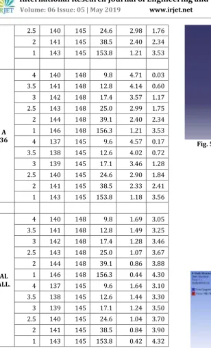
All Iterations According to the all three cases are tabulated below:
Thick Inner Outer Stress Final Weight Diff.
MS
4 140 148 9.8 4.74 0.00
3.5 141 148 12.8 4.17 0.57 3 142 148 17.4 3.59 1.15 2.5 143 148 25.0 3.01 1.73 2 144 148 39.1 2.42 2.32 1 146 148 156.3 1.22 3.52
4 137 145 9.6 4.60 0.14
3.5 138 145 12.6 4.05 0.69 3 139 145 17.1 3.49 1.25 2.5 140 145 24.6 2.92 1.82 2 141 145 38.5 2.35 2.39 1 143 145 153.8 1.19 3.55
MS 4 140 148 9.8 4.74 0.00
SS
304 4 140 148 9.8 4.85 0.11
-A
36 4 140 148 9.8 4.71 0.03
AL
ALL. 4 140 148 9.8 1.69 3.05
SS 304
4 140 148 9.8 4.85 0.11
-3.5 141 148 12.8 4.26 0.48 3 142 148 17.4 3.67 1.07 2.5 143 148 25.0 3.07 1.67 2 144 148 39.1 2.47 2.27 1 146 148 156.3 1.25 3.49
4 137 145 9.6 4.70 0.04
© 2019, IRJET | Impact Factor value: 7.211 | ISO 9001:2008 Certified Journal
| Page 7591
2.5 140 145 24.6 2.98 1.76 2 141 145 38.5 2.40 2.34 1 143 145 153.8 1.21 3.53
A 36
4 140 148 9.8 4.71 0.03
3.5 141 148 12.8 4.14 0.60 3 142 148 17.4 3.57 1.17 2.5 143 148 25.0 2.99 1.75 2 144 148 39.1 2.40 2.34 1 146 148 156.3 1.21 3.53
4 137 145 9.6 4.57 0.17
3.5 138 145 12.6 4.02 0.72 3 139 145 17.1 3.46 1.28 2.5 140 145 24.6 2.90 1.84 2 141 145 38.5 2.33 2.41 1 143 145 153.8 1.18 3.56
AL ALL.
4 140 148 9.8 1.69 3.05
3.5 141 148 12.8 1.49 3.25 3 142 148 17.4 1.28 3.46 2.5 143 148 25.0 1.07 3.67 2 144 148 39.1 0.86 3.88 1 146 148 156.3 0.44 4.30
4 137 145 9.6 1.64 3.10
[image:8.595.43.352.57.567.2]3.5 138 145 12.6 1.44 3.30 3 139 145 17.1 1.24 3.50 2.5 140 145 24.6 1.04 3.70 2 141 145 38.5 0.84 3.90 1 143 145 153.8 0.42 4.32
Table 5.5 - Iteration table according to all three cases
After studying all above iterations, the following shell was selected. It is as follows:
Thickness = 1 mm
[image:8.595.363.504.283.427.2]Outer Diameter = 148 mm Inner diameter = 146 mm Material = Mild steel
Fig. 5.1 – Geometric model of optimized shell
[image:8.595.322.545.452.580.2]Fig. 5.2 – Meshing of optimized shell
Fig. 5.3 – Boundary conditions for optimized shell
[image:8.595.322.546.612.739.2]© 2019, IRJET | Impact Factor value: 7.211 | ISO 9001:2008 Certified Journal
| Page 7592
Fig. 5.5 – Deformation analysis of optimized shell
6. RESULT AND DISCUSSIONS
After studying all above iterations, the following shell was selected. It is as follows:
Thickness = 1 mm
Outer Diameter = 148 mm Inner diameter = 146 mm Material = Mild steel
Total weight reduction of 3.52 Kg was obtained. It means total optimisation of 74.89 % is achieved.
Comparison of Stress on basis of Theoretical and analytical results:
Dimensions Design calculations
Results
Ansys Results
Thickness = 1 mm Outer Diameter = 148 mm Inner diameter = 146 mm
Stress Deflection Stress Deflection 156.3
Mpa 1.11 mm 156.35 Mpa 1.55 mm
Table 6.1 - Theoretical & analytical comparison of shell
7. CONCLUSION
Optimization was achieved on Shell of compressor. Some of components of system like motor assembly and vents are kept as it is due to its proper design. Design calculations, analysis model, and optimized system are compared on stress basis. The weight reduction achieved on shell does not affect the load carrying capacity of system. 3.53 Kg weight reduction is achieved by optimize design than existing design. 74.41 % of material was saved on optimized system than existing system which further save cost of system.
8. FUTURE SCOPE
The use of composite materials can be done for more weight reduction. This weight reduction can also bring a lightest compressor.
The skotch yoke mechanism is used to get rotary motion from the piston, this system can be optimised.
Use of heat treatments can also increase the surface strength and thus again thickness can be reduced.
Vibration analysis of whole system can be increase working capacity of system
9. REFERENCES
[1] Ashwani Kumar, Shaik Imran Behmad, Pravin P Patil, Thermo-Mechanical and Vibration Analysis of the I.C. Engine Piston made of SiC reinforced ZrB2 composite using Finite Element Method (ANSYS), IOSR Journal of Mechanical and Civil Engineering (IOSR-JMCE) e-ISSN: 2278-1684, p-ISSN: 2320-334X PP 19-23 www.iosrjournals.org International Conference on Advances in Engineering & Technology – 2014
[2] Jatender Datta*, Dr. Sahib Sartaj Singh, Heat Power Analysis on different materials of piston using finite element thermal analysis, International journal on recent researchers in science, engineering and technology, volume 5 isssue 10.
[3] K Ramesh Babu, G Guru Mahesh and G Harinath Gowd, Modeling and Thermal Analysis of Si Engine Piston Using Fem, ISSN 2278 – 0149 Vol. 3, No. 1, January 2014
[4] Dilip Kumar Sonar, Madhura Chattopadhyay, Theoretical Analysis of Stress and Design of Piston Head using CATIA & ANSYS, International Journal of Engineering Science Invention ISSN (Online): 2319 – 6734, ISSN: 2319 – 6726, Volume 4 Issue 6, June 2015 [5] T Arun Kumar Reddy, M Sachidhanand , Comparision
of two Different Materials for Connecting Rod using Ansys, IJIRST –International Journal for Innovative Research in Science & Technology| Volume 1 | Issue 11 | April 2015
[6] Leela Krishna Vegi, Venu Gopal Vegi, Design and Analysis of Connecting Rod Using Forged steel, International Journal of Scientific & Engineering Research, Volume 4, Issue 6, June-2013
[7] Vikrant K. Dhone, A.S. Rao, Vinaay Patil, “Comparative study of AISI4340 and Al7068 Connecting rod”, International Journal on Recent technologies in Mechanical and Electrical Engineering (IJRMEE), Vol-2, (2015), issue 7, ISSN- 2349-7947, page no. 1-4.
[8] Abhinav Gautam, K Priya Ajit “Static stress Analysis of Connecting Rod Using Finite Element Approach”, IOSR Journal of Mechanical and Civil Engineering, vol. 10, (2013), issue 1, ISSN-2320-334X, page no. 47-51. [9] A. Prem Kumar “Design and analysis of connecting rod