Interactive Animation: A new approach to simulate parametric studies
Darwin Sebayang and Ignatius Agung Wibowo Kolej Universiti Teknologi Tun Hussein Onn (KUiTTHO)
Abstract
Animation is the one of novel methods in using of electronic learning to explain engineering concepts, however many animations are only able to explain the working concept of a system and therefore do not provide an access to get into the variable of the system. This paper therefore presents example of interactive animations which can simulate virtual parametric study of single degree of freedom of spring-mass and projectile trajectory. These techniques will assist students to perform virtual parametric study and be a tool to derive mathematical relations.
1. Introduction
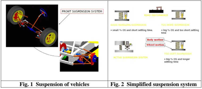
Fig. 1 Suspension of vehicles Fig. 2 Simplified suspension system
This paper presents therefore interactive animations that are not only visualize the engineering subjects but become a virtual laboratory to perform a parametric study in order to predict the behavior of the system. The interactive animation related to the suspension system of a vehicle is taken for an example. The primary objective of this interactive animation is to study the behavior of a system subjected to given excitations. The behavior of the system is characterized by the motion caused by the excitation and is commonly referred to as the system response. The motion is generally described by displacement, and less frequently by velocity or acceleration. A very important subject in a vibration study is the response of a system to external excitations.
2. The Techniques to Develop the Interactive Animation
Techniques to develop an interactive animation of free response of single-degree of freedom linear system will be discussed. It could be said that in general, the suspension of a vehicle can have many degrees of freedom. The simplest mathematical model of the suspension of a vehicle is a spring-mass-damper system. The vehicle of mass m is connected to its axle through a spring of stiffness k in parallel with a viscous damper of damping coefficient c [6], [7]. The procedure for obtaining the response of a system to an initial excitation including the influence of the spring and the damper is done by deriving the differential equation of that system.
The differential equation of a damped single degree of freedom is:
0 kx x c x
m&&+ & + =
The general solution to the above equation is:
t s t
s
e C e C t
x 1 2
2 1
)
( = +
where C1 and C2 are arbitrary constant to be determined from initial condition of the
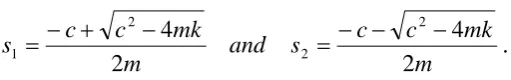
m mk c c s and m mk c c s 2 4 2 4 2 2 2 1 − − − = − + − = .
An interactive animation is developed based on that solution to create the virtual parametric study of single degree of freedom. The animation was created using Macromedia Flash MX 2004 Professional and was made interactive by programming using action script. Although there are other programming languages which were able to produce this kind of interactive animation, such as C++ and Visual Basic, however, Macromedia Flash MX 2004 Professional was chosen as the development software because it has complete package such as drawing editor, timeline animation, and action script which is an object oriented programming language. Moreover, the result is compact in size and easy to publish.
At first, all necessary objects like a mass, spring, display, etc. were drawn using drawing editor. Layers were used to organize the components of the drawing. Afterward, codes, based on the formulas which were derived before, were embedded into the objects and sometimes the layers to animate the objects. Lastly, interactivity is added by creating programmed buttons, sliders, and draggable objects.
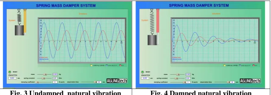
[image:3.595.91.347.69.109.2]3. Interactive Animation to Simulate Parametric Studies
Fig. 3 Undamped natural vibration Fig. 4 Damped natural vibration
4. Another Example of an Interactive Animation for Parametric Studies
[image:4.595.193.419.544.716.2]Another example of the interactive animation is the projectile motion as a function of the departure angle and initial speed. Visualization of the projectile position versus time indicates the trajectory of the projectile. A projectile is any body that is given an initial velocity and then follows a path determined entirely by the effects of gravitational acceleration and air resistance. A batted baseball, thrown football, package dropped from an airplane and bullet shot from a rifle are all projectiles. The path followed by a projectile is called its trajectory. The analysis of this common type of motion is started with an idealized model, representing the projectile as a single particle with an acceleration (due to gravity) that is constant in both magnitude and direction [8]. The effects of air resistance are neglected as well as the curvature and rotation of the earth. Like all models, this one has limitation; the curvature of the earth has to be considered in the flight of long range missile, and air resistance of crucial importance to a sky diver. Nevertheless, a lot of things can be learned from the analysis of this simple model. The key to analyze the projectile motion is that the x- and y-coordinates are treated separately. The x-component of the acceleration is zero, and the y-component is constant and equals to g. (Remember that by definition, g is always positive, irrespective with our choice of coordinated direction). So the projectile motion can be analyzed as a combination of the horizontal motion with constant velocity and vertical motion with constant acceleration.
Fig. 5 shows the interactive animation of the projectile motion. Students can change the initial speed or departure angle. Different input data will give a different trajectory. In this way, the students can easy understand the influence of the related parameter. The animation can also help lecturers to derive the mathematical equation related to the problem.
5. Conclusions
The animation has become a new technique to explain the engineering concept and can be used as a virtual laboratory for parametric studies. The visualization of the concept can enhance the exploration new ideas. The virtual instrumentation will be developed in the future in order that students can learn and simulate much more experimentations.
References
[1] Michelle L. Grifftit et. al., “The Success of Multimedia Courseware in the Manufacturing Engineering Education Partnership (MEEP) Program”, TRP/MET Conference, April 7-8,1997
[2] Malgorzata S.Zywan et. al, “Effective Integration of Multimedia Courseware in Engineering Education at Rysen Polytechnic University”, Global J. of Engineering Education, Vol. 4 No. 1, 2000
[3] Noronha, M. et. al., “Multimedia - based Environment in Structural Engineering Education”
[4] Wilson. Liang, “Using Multimedia in Teaching Dynamics”, in Proceeding of the 2002 Conference for Industry and Education Collaboration, 2001
[5] Sebayang . Darwin, “E-Module of Fluid Power”, KUiTTHO, 2003
[6] Graham Kelly, Fundamental of Mechanicals Vibration, Mc Graw Hill, 2000
[7] Sebayang. Darwin, W. Seto, Getaran Mekanis (Mechanical Vibration), Penerbit Erlangga, 1985.