warwick.ac.uk/lib-publications
A Thesis Submitted for the Degree of PhD at the University of Warwick
Permanent WRAP URL:
http://wrap.warwick.ac.uk/106724
Copyright and reuse:
This thesis is made available online and is protected by original copyright.
Please scroll down to view the document itself.
Please refer to the repository record for this item for information to help you to cite it.
Our policy information is available from the repository home page.
TITLE
BPCHLIMH 1» C0HTIHP008 COMPOSITE BEAMSAUTHOR
Chun Keung Roger FanINSTITUTION
and DATE
Univeraity of Warwick l<RAOAttention is drawn to the fact that the copyright of
this thesis rests with its author.
This copy of the thesis has been supplied on condition
that anyone who consults it is understood to recognise
that its copyright jests with its author and that no
information derived /rbm it may be published w itho ut
the author's prior written consent.
T H E BRITISH LIBRARY
D O C U M E N T S U f f l Y C E N T R I — TÌ TÏ Tl Vi ri T •
cm»
Boston Spa. Wetherfcy West Yorkshire
by
Chun Kaung Rogar ran BSc, MSc, DIC
A thasia for tha degree of
Doctor of Philosophy,
submitted to tha University of Warwick
Department of Engineering,
University of Warwick, England
li
Declaration
The work described in this dissertation was carried
out by the candidate between September 1986 and December
1989 in the Department of Engineering at the University
of Warwick under the supervision of Professor R. P.
Johnson. Unless otherwise where reference is made
to the work of others, this dissertation describes
the original work of the author. It has not been
submitted for a degree at any other University.
C. K . R. Pan
University of Warwick
Coventry,
Su— ary
Two aspects of tha buckling behaviour of continuous composite beams of steel and concrete are considered. The first part relates to the study of moment redistribution in braced slender beams ( Class 3 draft Eurocode 4)
due to local buckling in the hogging moment regions. The
second part describes the experimental work to investigate the ultimate load behaviour of unbraced compact beams (Classes 1 and 2 draft Eurocode 4) in the hogging moment regions.
For a braced continuous slender composite beam, local buckling at an internal support allows a redistribution of bending moment from the hogging regions to the sagging
regions, in addition to material nonlinearity. This
effect was studied by a computer simulation on two-span
beams. The program takes into account not only the effect
of local buckling, but also material nonlinearity and
residual stresses, on moment redistribution. The ultimate
loads designed to the less conservative method for Class 3 beans in the draft Eurocode 4 were used as a datum in the
parametric study. The simulation then gave an independent
assessment of the appropriateness and safety of these
loads at the ultimate limit state. It is shown that the
design method is slightly conservative. Residual stresses
have very little effect on the ultimate carrying capacity. Furthermore, in design to the draft Eurocode 4, unpropped construction is more restrictive than propped construction, and hence the results are also more conservative.
Lateral buckling of continuous unbraced composite beams in the hogging moment regions can only occur in a dlstortional mode, and is most unlikely to happen in practical building or bridge structures using hot-rolled steel sections of
span up to about 30m. Various design methods based on
numerical studies now exist to predict the ultimate strength of continuous composite beams affected by distortional
lateral buckling, but few experimental results
are available to validate their theoretical assumptions
and accuracy. Tests at realistic scale on two T-beams
and two inverted U-frames at the Class 2-3 Interface, in
accordance with the draft Eurocode 4, are reported. Their
results are compared with predictions by five design methods, four of which are satisfactory for the beams tested except
BS5400iPart 3. Due to premature fracture of reinforcing
fabric in one of the U-frame tests, it is recommended not to Include their contribution in moment resistance, when the composite cross-section is plastic and a design requires a large amount of rotation capacity in the hogging moment
regions. Based on limited test results, a tsntative method
Contents
iv
Acknowledgements i
Declaration u
Summary U |
Contents ¿v
List of Tables x i
List of Figures xiii
List of Plates xx
Notation xxii
CHAPTER 1 INTRODUCTION 1
1.1 Preamble 1
1.2 Objectives of the project 5
1.2.1 Redistribution of moment 5
1.2.2 Experimental work on distortional
lateral buckling 7
CHAPTER 2 PREVIOUS RESEARCH AND THEORETICAL 10
MODELS
2.1 Introduction 10
2.2 Local buckling 12
2.3 Classification of cross-sections 16
2.4 Moment redistribution 19
2.5 Design of class 3 continuous composite 22
beams
2.6 Theoretical studies on distortional 24
lateral buckling
2.6.1 Plain steel beams 26
2.6.2 Composite beams 30
2.6.2.1 Codified methods in U.K. 31
2.6.2.2 Distortional buckling 38
analysis as a bifurcation problem
2.6.2.3 Non-linear large deflection 44 analysis
2.6.2.4 Strut on elastic foundation 46
2.6.2.5 Energy method with web 53
distortion
2.7 Experimental work on distortional lateral 58
buckling
Figures 2.1 - 2.13 62
CHAPTER 3 NUMERICAL ANALYSIS OF MOMENT 74
REDISTRIBUTION IN CLASS 3 CONTINUOUS COMPOSITE BEAMS
3.1 Introduction 74
3.2 Material properties 75
3.3 Elasto-plastic moment-curvature 76
characteristics
3.4 Mathematical model for a two-span 79
continuous beam
3.4.1 Pre-local-buckling model 79
3.4.2 Post-local-buckling model 83
3.5 Flexural stiffnesses and load arrangements 87
3.6 Method of analysis 90
3.6.1 Moment-curvature relationships 90
3.6.2 Details of the computer program 91
3.6.3 Accelerated iteration scheme 95
3.7 Convergence test and program validation 97
Figures 3.1 - 3.4 99
CHAPTER 4 RESULTS OF PARAMETRIC STUDY ON 103
MOMENT REDISTRIBUTION
4.1 Introduction 103
4.2 Choice of members for study 105
4.2.1 Cross-sections 105
Vi
Pag*
4.2.3 Loadings and factors 107
4.2.4 Propsrtiss of materials and Ym factors 108
4.3 Numerical results 109
4.3.1 Comparison between cantilevers 109
and tvo-span beams
4.3.2 Tvo-span beams 109
4.4 Analysis and discussion 110
4.4.1 Load factors and Xf 110
4.4.2 Effect of unpropped construction 110
4.4.3 Residual stresses 111
4.4.4 Span ratio 112
4.4.5 Sensitivity of Xf to the slope of 113
the falling branch
4.4.6 Combined bending and shear 113
4.5 Comments on the design method of draft 115
Eurocode 4
4.6 Conclusions 117
Tables 4.1 - 4.4 119
Figure 4.1 122
CHAPTER 5 TESTS TO INVESTIGATE DIST0RTI0NAL 123
LATERAL BUCKLING - T-BEAMS
5.1 Introduction 123
5.2 Choice of specimens 125
5.3 Details of test specimens 127
5.3.1 Beam 32 127
5.3.2 Beam U1 127
5.4 Construction of test specimens 129
5.5 Testing rigs 130
5.6 Instrumentation 132
5.6.1 Beam 32 132
Page
5.7 Auxiliary tasta 135
5.7.1 Calibrations 135
5.7.2 Matarial properties 135
5.7.3 Cross-aectional dimensions and 136
imperfections
5.7.4 Residual stress measurements 137
5.7.5 Instrumentation check 137
5.8 Test procedures 138
5.8.1 Beam S2 138
5.8.2 Beam U1 138
Table 5.1 140
Figures 5.1 - 5.12 141
Plates 5.1 - 5.7 152
CHAPTER 6 TEST RESULTS OF T-BEAMS AND 156
DISCUSSION
6.1 Introduction 156
6.2 Material properties 157
6.3 Cross-sectional dimensions and 158
imperfections
6.4 Residual stresses 159
6.5 Compactness and beam resistance 160
6.6 Teat resulta 161
6.7 Behaviour of beams during test 163
6.8 Accuracy of results 165
6.9 Discussion of test results 166
6.10 Conclusions 171
Tables 6.1 - 6.10 173
Flgurss 6.1 -6. 29 178
vili
CHAPTER 7 TESTS TO INVESTIGATE DISTORTIONAL 208
LATERAL BUCKLING - INVERTED U-BEAMS
7.1 Introduction 208
7.2 Choice of specimen 210
7.3 Details of test specimens 211
7.3.1 Specimen U2 211
7.3.2 Specimen U3 211
7.4 Construction of test specimens 213
7.5 Testing rigs 215
7.6 Instrumentation 218
7.6.1 Specimen U2 218
7.6.2 Specimen U3 219
7.7 Auxiliary tests 220
7.7.1 Material properties 220
7.7.2 Cross-sectional dimensions and 221
imperfections
7.7.3 Instrumentation check 221
7.8 Test procedures 223
7.8.1 Specimen U2 223
7.8.2 Specimen 03 224
Plgurea 7.1 - 7.21 228
Plates 7.1 - 7.6 249
CHAPTER 8 RESULTS OP INVERTED U-BEAM TESTS 255
8.1 Introduction 255
8.2 Material properties 256
8.3 Cross-sectional dimensions and initial 257
Imperfections
8.4 Residual stresses 258
8.5 Compactness and beam resistance 259
Tables 8.1 - 8.9
Figures 8.1 - 8.43
Plates 8.1 - 8.8
CHAPTER 9 ANALYSIS AND DISCUSSION OF THE
INVERTED U-BEAM TESTS
9.1 Introduction
9.2 Accuracy of results
9.2.2 Accuracy of calculations on the plastic moment of resistance
9.3 Strain softening behaviour
9.3.1 Moment-rotation characteristic
9.3.2 Load-displacement relationship
9.3.3 Transverse rotations of flanges
9.3.4 Strain measurements
9.4 Discussion
9.5 Figures
Conclusions 9.1 - 9.2
CHAPTER 10 DESIGN RECOMMENDATIONS FOR
DISTORTIONAL LATERAL BUCKLING
10.1 Introduction
10.2 Comparisons between the test results and
predictions from various design methods
10.3 Flexural rigidity of the slab
10.4 Flexibility of the web
10.5 Modified lateral slenderness
10.6 Other design considerations
10.7 Tentative design method
Tables 10.1 1 0 . 2
x
367 Pag«
Figures 10.1 - 10.4 369
REFERENCES 373
APPENDICES 392
APPENDIX A Publication
'Strength of continuous composite beams d««ign«d to Eurocod« 4'
393
APPENDIX B Tvo-span beam d««lgn examples 406
APPENDIX C Calculations for classification
of cross-section for th« test specimens, S 2 , Ul, U2 and U3
410
APPENDIX D Proposed design method for lateral-
torslonal buckling of composite beams in the second draft of Eurocode 4
ot r.bi..
Tabi*
CHAPTER 4
Page
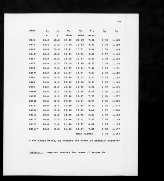
4.1 Computed results for beams of series SB 119
4.2 Computed results for beams of series TB 120
4.3 Results for unpropped construction 121
4.4 Comparison of load levels between propped
and unpropped construction
121
CHAPTER 5
5.1 U1 strain gauge type and classification 140
CHAPTER 6
6.1 Properties of concrete for beam S2 173
6.2 Tensile test results for specimen U1 173
6.3 Tensile test results for high-yield
A193 fabric
173
6.4 Properties of concrete for beams U1 and U2 174
6.5 Cross-sectional dimensions of specimens
02 and U1
174
6.6 Residual stress measurements for specimen U1 175
6.7 Classification of cross-section for
specimens S2 and U1
175
6.0 176
6.0 S2 test results 176
6.10 U1 tsst rssults 177
CHAPTER 0
0.1 Structural steel properties of specimen
U2 and U3
267
0.2 Material properties of 8mm high-yield bars 207
0.3 Compressive strength of ready-alx concrete
for U3 specimen
xii
Table Page
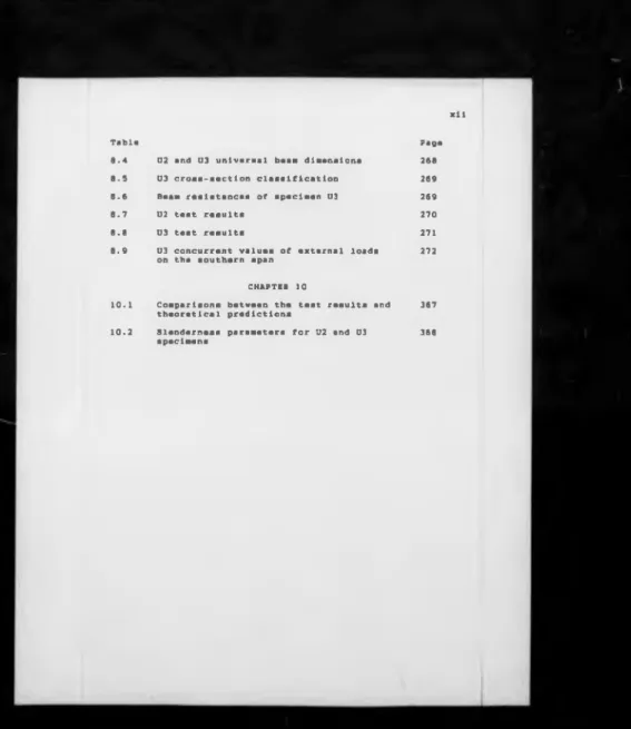
8.4 U2 and U3 universal beam dimenaiona 268
8.5 U3 cross-section classification 269
8.6 Beam reslatancea of apecimen U3 269
8.7 U2 teat results 270
8.8 03 test results 271
8.9 U3
on
concurrent values of external loads the southern span
272
CHAPTER 10
10.1 Comparisons between the test results and
theoretical predictions
367
10.2 Slenderness parameters for U2 and U3
specimens
368
Figure
Lt.t or riaare.
Page
CHAPTER 2
2.1 Strain diatrlbutiona for composite and 62
plain ateel sections in hogging bending
2.2 Moment-rotation curves for profiles with 63
different croae-aectional classes
2.3 Instability of continuous composite beams 64
in the hogging moment region
2.4 U-frame action proposed by BS5400tPart 3 65
2.5 Beam buckling behaviour (adopted from 66
Reference 116)
2.6 Typical composite cross-eection 67
2.7 Computer model used by Weston (Ref. 77) 68
2.6 Comparison of predictione between the 69
design methods propoeed by Bradford and Johnaon (Ref. 5) and Weston (Ref. 77)
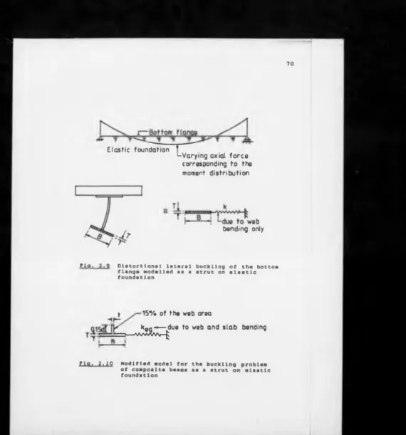
2.9 Dietortlonal lateral buckling of the bottom 70
flange modelled as a strut on elastic foundation
2.10 Modified model for the buckling problem 70
of composite beams as a strut on elastic foundation
2.11 Analytical model used in the draft lurocode 71
4 for dlstortlonal lateral buckling of composite beams
2.12 Experimental results of composite double 72
cantilever tests showing dlstortional lateral buckling plotted against web flexibility
2.13 Experimental results of composite double 73
cantilever tests showing dlstortlonal lateral buckling plotted against bottom strut slsndsrnsss
3.1
CHAPTER 3
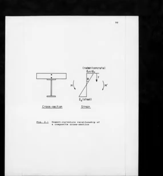
Moment-curvaturs relationship of a 99
composlts cross-section
xiv
rigur. Pag#
3.3 Flow chart for th« computer analysis 101
3.4 Study of convergane« (specimen SB42) 102
CHAPTER 4
4.1 Interaction diagram for combined bending
and shear of Class 3 beams (E C 4 ) designed in accordance with BS5400: Part 3
122
CHAPTER 5
3.1 Continuous composite beam modelled as an
unsymmetrleal double cantilever 141
3.2 Elevation and cross-section of beam S2 141
3.3 Elevation and cross-section of beam 01
and testing arrangement
142
3.4 Central support details of beam S2 143
3.3 End reaction details of beam S2 144
3.6 Internal support details of beam U1 143
3.7 End reaction details of beam U1 146
3.8 Instrumentation positions for beam S2 147
3.9 Instrumentation positions for beam U1 148
3.10 Strain gauge positions for beam 01 149
3.11 Positions of coupon samples 130
3.12 131
CHAPTER 6
6.1 Lateral displacements of the bottom
of beam 82
flange 178
6.2 Lateral displacements of the bottom
of beam U1 flange 179
6.3 Residual stress pattern of beam U1 180
6.4 Moment-rotation curves of beam S2 161
6.3 Relationship between the lateral
displacement measurement and rotation of the bottom flange for beams 82 and U1
6.6 Lateral displacement of the bottom flange of beam S2 at monitoring point 3 in Fig. 5.8
183
6.7 Lateral displacement of the bottom flange
of beam S2 at monitoring point 5 in Fig. 5.8 184
6.8 Support moment versus bottom flange
transverse rotations for beam S2 (south side! 185 1
6.9 Support moment versus bottom flange
transverse rotations for beam S2 (north side] 186 1
6.10 Support moment versus concrete flange
transverse rotations for beam S2
187
6.11 Moment-rotation curve of beam U1 188
6.12 Lateral displacements of bottom flange
of beam U1 at position LI
189
6.13 Lateral displacements of bottom flange
of beam U1 at position SI
190
6.14 Support moment versus flange transverse
rotations for beam U1 (short span)
191
6.13 Support moment versus flange transverse
rotations for beam U1 (long span)
192
6.16 Support moment versus bottom flange
transverse rotations for beam U1 (long span) 193
6.17 Compressive strains of the bottom flange
along the beam for beam U1
194
6.18 In-plane bending strains of the bottom
flange along the beam for beam U1
195
6.19 Out-of-plane bending strains of the web
for beam U1
196
6.20 Strains of rosette LR1 for beam U1 197
6.21 Principal strains and direction of
rosette LR1 for beam U1
198
6.22 Strains of rosette LR4 for beam U1 199
6.23 Principal strains and direction of
rosette LR4 for beam U1
200
6.24 Strains of rosette SRI for beam U1 201
6.23 Principal strains and direction of
xvi
Figure Page
2.26 Strains of rosette SR3 for beam U1 203
2.27 Principal strains and direction of 204
rosette SRI for beam U1
6.28 Strains of rosette SR4 for beam U1 205
6.29 Principal strains and direction of 206
rosette SR4 for beam U1
CHAPTER 7
7.1 Geometry of the inverted U-frame specimen 228
U2
7.2 Cross-section of specimen U2 229
7.3 Geometry of the inverted U-frame specimen 230
U3
7.4 Cross-section of specimen U3 231
7.5 Slab reinforcement details of specimen U3 232
7.6 Central support details of specimen U2 233
7.7 Bearing details at the northern end of 234
specimen U2
7.8 Bearing details at the northern end of 235
specimen U3
7.9 Bearing details at the southern end of 236
specimen U3
7.10 Loading system for the simulation of 237
uniformly distributed loads in test U3
7.11 End view of the line loading in test U3 238
7.12 Location of strain gauges for beam U2A 239
7.13 Location of strain gauges for beam U2B 240
7.14 Monitoring points for transverse rotations 241
of the flanges for specimen U2
7.15 Monitoring points for lateral displacements 242
of the bottom flanges for specimen U2
7.16 Positions of instrumentation for specimen U2 243
7.17 Location of strain gauges for beam U3A 244
Figure Page
7.19 Monitoring pointa for transverse rotations
of the flanges for specimen U3
246
7.20 Monitoring points for lateral displacements
of the flanges for specimen U3
247
7.21 Loading arrangement of test U3 248
CHAPTER 8
8.1 Initial lateral imperfections of the bottom
flanges for specimen U2
273
8.2 Initial lateral imperfectiona for specimen
U3
274
8.3 Moment-rotation curvea for beams U2A and U2B 275
8.4 Moment-rotation curves for beams U3A and U3B 276
8.5 Support moment versus vertical aupport
movement for beama U2A and U2B
277
8.6 Sign convention for U2 teat 278
8.7 Sign convention for U3 teat 279
8.8 Lateral diaplacementa of bottom flange
along beam U2A
280
8.9 Lateral diaplacementa of bottom flange
along beam U2B
281
8.10 Beam U2A bottom flange lateral diaplacementa 282
8.11 Beam U2B bottom flange lateral diaplacementa 283
8.12 Transvarae rotatlona of bottom flange
along beam U2A
284
8.13 Tranaverae rotationa of bottom flange
along beam U2B
285
8.14 Beam U2A concrete flange transverae
rotatlona
286
8.15 Beam U2A bottom flange transverae rotationa 287
8.16 Beam U2B concrete flange tranaverae
rotationa
288
8.17 Beam U2B bottom flange tranaverae rotations 289
8.18 Compreaalve stralna of bottom flange 290
along beam U2A
Figure Page
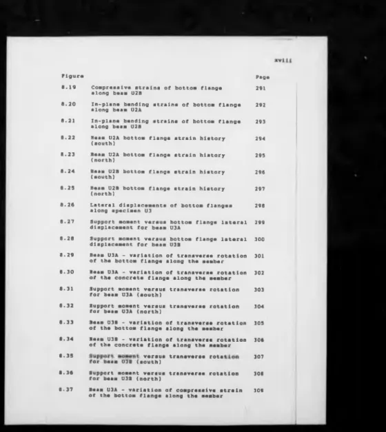
8.19 Compressive strains of bottom flange
along beam U2B
291
8.20 In-plane bending strains of bottom flange
along beam U2A 292
8.21 In-plane bending strains of bottom flange
along beam U2B
293
8.22 Beam U2A bottom flange strain history
(south) 294
8.23 Beam U2A bottom flange strain history
(north)
295
8.24 Beam U2B bottom flange strain history
(south)
296
8.23 Beam U2B bottom flange strain history
(north) 297
8.26 Lateral displacements of bottom flanges
along specimen U3
298
8.27 Support moment versus bottom flange lateral
displacement for beam U3A
299
8.28 Support moment versus bottom flange lateral
displacement for beam U3B
300
8.29 Beam U3A - variation of transverse rotation
of the bottom flange along the member
301
8.30 Beam U3A - variation of transverse rotation
of the concrete flange along the member 302
8.31 Support moment versus transverse rotation
for beam U3A (south)
303
8.32 Support moment versus transverse rotation
for beam U3A (north)
304
8.33 Beam U3B - variation of transverse rotation
of the bottom flange along the member
303
8.34 Beam U3B - variation of transverse rotation
of the concrete flange along the member 306
8.33
for beam U3B (south)
307
8.36 Support moment versus transverse rotation
for beam U3B (north)
308
8.37 Beam U3A - variation of compressive strain
of the bottom flange along the member
Figure Page
8.38 Beam U3A - variation of in-plane bending
strain of the bottom flange along the member 310
8.39 Beam U3B - variation of compressive strain
of the bottom flange along the member
311
8.40 Beam U3B - variation of in-plane bending
strain of the bottom flange along the member 312
8.41 Beam U3A - variation of out-of-plane
bending strain of the web along the member 313
8.42 Beam U3B - variation of out-of-plane
bending strain of the web along the member 314
8.43 Lateral movement of concrete slab for
specimen U3
315
CHAPTER 9
9.1 Idealization of the positions of reaction
on U3 slab for the line loading
344b
9.2 Strain distribution across a composite
cross-section
344b
CHAPTER 10
10.1 Transformed cross-section of reinforced
concrete slab
369
10.2 Experimental results versus web flexibility 370
10.3 Experimental results versus bottom flange
strut slenderness
371
10.4 Cracked composite cross-section in hogging
bending
Lift Of Platef Plate
CHAPTER 5
Page
5.1 Test rig for beam S2 152
5.2 End bearing for beam S2 152
5.3 Test rig for beam U1 153
5.4 Double jack system and vertical channel
guide in test U1
154
5.5 Central support details for beam U1 154
5.6 Adjustable edge lateral restraint for
beam U1
155
5.7 Instrumentation for the measurement of
lateral displacement for beam U1
155
CHAPTER 6
6.1 Failure of specimen U1 207
CHAPTER 7
7.1 Diagonal bracings at the supports for
specimen U2
249
7.2 Test rig for specimen U2 250
7.3 Vertical guide rails to prevont lateral
jack movement for specimen U2
251
7.4 Test rig for specimen U3 252
7.5 End vie w of test rig for specimen U3 253
7.6 Line loading set-up for specimen U3 254
CHAPTER 8
8.1 Crack pattern in concrata slab for 316
spaciman U2
8.2 Wavelength and amplituda of tha local buckla 317
for baam U2A
8.3 Local buckling in baam U2A 317
Plate Page
8.5 Interaction of local and lateral buckling
in beam U2B
318
8.6 Local buckling in beam U3A 319
8.7 Local buckling in beam U3B 319
8.8 Crack pattern in concrete slab for
xxii j
Notation
B, b breadth of steel section
1 b °
outstand of flange In compression or breadth of steel section
1 D > ». overall depth of steel section
t, tw , w, TW thickness of web of steel section
1 d clear depth of steel web between flanges
t thickness of flange of steel section
(Chapters 3 and 4 only)
*c compressive strain of bottom fibre
♦ hogging and sagging curvatures
N * , H hogging and sagging moments at an internal
support and midspan
V ' V plastic and first yield hogging moments of
resistance for a composite cross-section 1
V "y plastic and first yield sagging moments of
resistance for a composite cross-section
1 R rotation capacity *
«P available and plastic rotations in hogging |
moment region (Fig. 2.2) |
X ductility parameter for composite beams |
*LT lateral torsional buckling slenderness |
parameter (BS5400: Part 3) |
«li
6, A lateral deflection of unrestrained bottom 1
flange or linear displacement |
L length of a member or span of a beam 1
,or
elastic critical buckling load 1E. E. Young's modulus for structural steel 1
G shear modulus for structural steel 1
J St.Venant torsion constant for steel !
*• effective length
*p plastic section modulus of steel or
composite section
*XC' *xt elastic section moduli of steel or
composite section with respect to compressive and tensile fibres
Xcr critical load factor
®cr' fcr elastic critical buckling stress
P modified buckling slenderness parameter
for composite beams
fy yield stress of reinforcement or
structural steel
Pi* Pd local and distortional buckling
slenderness parameters
Pf' Pw flange and web slenderness ratios for
a composite beam
°y yield stress of structural steel
ry radius of gyration of bottom flange
about minor axis of steel section
yt maximum tensile fibre distance from
elastic neutral axis
k web flexural stiffness, N/mm
(K) elastic stiffness matrix
(0) stability matrix
V Poisson's ratio for steel
ad, a'd depths of web in compression using elastic
and plastic theories
H. H0 applied a n d critical compressive forces
to bottom flange due to bending moment for a continuous beam
Z second moment of area for steel section
pi dimensionless modulus for web flexural
stiffness
& dimensionless slenderness for buckling
xxiv
ZY sacond moment of are* for steel section
about minor axis
^cr critical buckling length
«or elastic critical buckling moment for a
composite beam
n, C4 slenderness correction factors for shape
of bending moment diagram
vt slenderness correction factor for
torsional effect, web distortion and position of shear centre, etc
*LT lateral torsional buckling slenderness
factor (draft Eurocode 4)
lo. Lol. Lo2 distance between an internal support and
point of contraflexure for a continuous beam, or length of a cantilever
rcp radius of gyration of portion of web and
bottom flange in compression below plastic neutral axis about minor axis of steel section
*r' *rt total area of slab longitudinal
reinforcement
bc , hc breadth and depth of concrete slab
zou characteristic cube strength of concrete
I0 , Iu cracked and uncracked second moments of
area for composite cross-section
peak hogging moment in cantilever test
V maximum applied shear force
VP1- VP shear capacity • o ydw/V3
»1« *2 design loads for a two-span beam
tl. I2 span lengths of a two-span beam
Ym- * partial safety factor for a material
Y f Yr partial load factors
•• total rotation at the end of a cantilever
f
-J
*
V irreversible rotation of a quasi
cantilever in a continuous beam when M'-My'
®bc' irreversible rotation of a cantilever when
M'-My'
elastic rotation
•i-•r
irreversible rotation
strains corresponding to curvature +
residual strains
». longitudinal stresses across steel section
». cross-sectional area of steel section
a rt longitudinal stress in reinforcement
X load factor
buckling and failure load factors
m ratio of cracked to uncracked flexural
stiffness for a composite cross-section
modular ratio
« tolerance limit for convergence
9. q characteristic dead and imposed loads
fu ultimate stress for steel or reinforcement
>r secant modulus of elasticity at 0.1%
strain for reinforcement or fabric
thickness of top flange of steel section
tb f, TB thickness of bottom flange of steel
section
• experimental beam rotation for a double
cantilever
•o> ®. transverse rotations of concrete and
bottom steel flange
«O- H> compressive and bending strains
WT, MB breadths of top and bottom flanges of
XXVi.
Ac- A ,
♦
At. a b
A,
A.
c0- A,
lateral diaplacemente of concrata and bottom steel flanges In U-frame tests
diameter of reinforcing bars or fabric (Chapter 9)
areas of top and bottom reinforcement per metre strip of concrete slab
distance between top slab and centroid of reinforcement (Fig. 10.1)
second moment of area of concrete or composite slab per metre strip
distance between two adjacent steel sections in an inverted U-frame
distance between shear centres of flanges
elastic critical buckling moment for steel section
1.1 Praambl*
In recent years composite construction has become a
popular fast-track method of construction in U.S.A. and
Western Europe. For the past five years over 50% of the
new commercial steel buildings in these areas are either
composite or semi-composite. This rapid growth is a
result of continuous innovations in the design and
construction of composite structures, and also encourages
further research and development. Two new codes of
practice for design in composite construction, Eurocode
and BS5950 : Part 3.1 # both in draft form, are
now available for public comments.
Composite beams are vital components in a composite steel
structure, and have been a subject of research since the
1950's. The composite beams considered here are made up
of unstiffened steel Z-sections, welded stud shear
connectors, and insitu concrete slabs above, with or
without metal decking. In current practice composite
beams are usually designed as simply-supported, but at
longer spans, their deflections due to service loads
would probably govern the design rather than the
strength, that might lead to the use of deeper steel
/
2
design does not make use of the strength of the beam
economically and increases the material cost, but also
there will be a reduction in the effective floor zone.
An alternative approach to improve the economy and to
limit excessive deflections is to design composite beams
as continuous.
This project forms part of a long-term study into the
ultimate behaviour of continuous composite beams in the
region of an intermediate support. Many problems have
been tackled previously including the effect of local
buckling, ultimate moment of resistance, ultimate shear
capacity, partial shear connections, design of semi-rigid
joints in composite frames, redistribution of moments,
cracking, and more recently distortional lateral buckling
of the b o t t o m flange. In hogging moment regions.
buckling is one of the structural problems facing
designers as far as the stability of the beam is
concerned. If it has a slender cross-section and is
braced laterally, part of the web and the bottom flange
under compression are prone to local buckling O ) , that
might reduce its hogging moment of resistance and
rotation capacity. For beams with long unbraced hogging
regions, the steel bottom flange may be susceptible to
distortional lateral buckling (4*5,6)' often associated
and interacting with local buckling adjacent to an
intermediate support, causing a decline in its bending
according to bot h draft Eurocode 4 and BS5950 : Part 3.1,
depending on the flange and web slenderness ratios of the
steel section. The classification system is explained
briefly in Chapter 2 and this project adopted the
terminology and rules given by draft Eurocode 4 closely
in terms of classification of cross-sections. The work
reported here consists of studies of two aspects of the
ultimate behaviour of continuous composite beams affected
by buckling in the hogging regions: (i) a parametric
study to investigate the amount of moment redistribution
for braced beams with Class 3 (slender) cross-section
that occurs due to local buckling; and (ii) an
experimental study to investigate the effect of local
buckling and distortional lateral buckling as well as
their interaction, and their influence on the ultimate
moment of resistance, for unbraced beams with Class 2
(compact) cross-section. The scope of the project applies
to the design of both building structures and medium span
viaducts, but excludes long span (over 30 m) highway
bridges.
In this thesis, the first chapter describes the
objectives of the project. The next chapter gives a
review of literature and previous work related to moment
4
composite beams, a n d also presents the current design
procedures regarding the latter. This is followed by the
report of the numerical work on moment redistribution for
Class 3 continuous composite beams. The first part
(Chapter 3) describes the computer program used in the
study and the second part (Chapter 4) presents the
results of the parametric study and conclusions. The
experimental work on distortional lateral buckling is
reported in three parts. The first (Chapters 5 and 6)
describes the tests on two double cantilevers (T beam)
labelled as T1 and Ul, and the second (Chapters 7,8 and
9) describes the tests on two inverted-U frames acting as
double cantilevers labelled as U2 and U3. Results and
discussions are given in Chapters 6 and 9 for each series
respectively. In Chapter 10, all the experimental
results are then discussed and compared with theoretical
predictions from various design methods described in
Chapter 2. Finally conclusions and tentative design
recommendations for distortional lateral buckling are
also given in Chapter 10.
The Système Internationale (S.I.) units are used for
measurement throughout this thesis. In all the figures
linear dimensions are in mm unless otherwise stated.
1.2 Objectivas of the project
1.2.1 Redistribution o f moment
In bracsd continuous composite beams, redistribution of
bending moment occurs from the hogging regions to the
sagging regions as a result of concrete cracking,
material yielding and local buckling. This makes a
significant departure between the true distribution of
moments and that expected from elastic analysis. By
satisfying the compatibility requirements imposed by the
boundary conditions, the amount of redistribution can be
determined by a numerical simulation using realistic
inelastic moment-curvature relationships and
characteristic moment-rotation curves of the hogging
regions due to local buckling. Previous research had
been carried out on beams with Class 1 or 2 cross-section
to justify the use of the simple plastic collapse design
method, and to identify the limitations of its
application. The research described here is concerned
with the design of uniform continuous composite beams
with Class 3 cross-section, and the amount of moment
redistribution permitted within which a beam can still
resist the design load p rior to failure.
In design to draft Eurocode 4 (ECi)^1), there are two
analysis of Class 3 continuous beams. Apparently one
method is less conservative than the other, and it allows
up to 20 per cent redistribution of hogging moments
determined by elastic cracked analysis, in the belief
that local buckling can provide sufficient increase in
rotation capacity in the hogging regions, without causing
a rapid decline of the hogging moment of resistance, to
shed at least this amount of bending moment to the mid
spans before collapse occurs. The objective of the work
was to identify the margin of safety of this less
conservative method by a computer study, using realistic
material properties and the limited test data on the
post-local-buckling behaviour of cantilevers with Class 3
cross-section, over a wide range of beams with practical
dimensions. In the parametric study, it was assumed that
complete shear connection was provided, and that the
bottom flange of the beams was braced against lateral-
For continuous composite beams the steel bottom flange
will normally be In compression over a length between the
two points of contraflexure adjacent to an internal
support. If the beam is unbraced, the bottom flange in
the hogging regions may be vulnerable to lateral-
torsional buckling, sometimes initiated by local buckling
adjacent to an internal support, depending very much on
the geometrical proportions of the web and the bottom
flange. This instability impairs the ultimate load
carrying capacity of the beam, and so sometimes bracings
are required in order to achieve an economic design
solution. BS5400: Fart 3< 8 > and draft BS5950 t Part
3 . 1 ^ ) give the requirements for bracing provision to
bridge girders and building beams respectively.
However, for beams with stocky cross-section (Class 1 or
2), such as hot-rolled universal beam sections used in
buildings and viaducts, it is widely believed that the
provision of lateral bracings is inconvenient, costly and
unnecessary. For a multi-beam floor system, the
torsional stiffness of the reinforced oonorete slab is
much stiffer than that of the steel section, and it seems
logical to assume that, depending on the flexural
8
the bottom flange the lateral a n d torsional restraints
provided to the top flange by the slab. Unfortunately
there is not sufficient experimental evidence to
substantiate this view. The composite beams of greatest
research interest have been those with Class 2 webs and
flanges in accordance with EC 4.
The scope of the present work is therefore limited to
composite beams with unstiffened w e b within the Class 2
limit. Although instability of the bottom flange could
undermine the ultimate strength of continuous composite
beams, little research had been done to tackle the
problem, both theoretically and experimentally. Until
recently a number of design methods, which use different
conceptual models and are mainly based on numerical
methods, have been proposed, and they are discussed in
detail in Chapter 2. The relevant conceptual model is
the continuous inverted-U frame, with at least two
parallel beams attached to the common slab by shear
studs, which may be either of reinforced concrete or a
composite slab with profiled steel decking. Tests have
been done on specimens of realistic scale to study the
buckling behaviour of composite beams in the hogging
moment region. The objectives of these tests were to
provide guidance regarding assumptions and modelling for
theoretical work, and also data on the ultimate hogging
Sine« a generally accepted mathod of assessing tha
susceptibility of tha hogging ragion to diatortional
lataral buckling is not yet availabla. Tha tast rasults
hava been uaad to provide apot checks on their
P r*dicti°ns and appropriateness of various methods
described in Chapter 2. Tha buckling phenomenon in
composite beams is rather complex, because it is
dependent upon many parameters, such as the geometrical
and material properties of the steel I-section, the
transverse bending stiffness of the concrete slab
atta°bed to the steel top flange, the amount of shear
connection, the type and position of the applied loads,
and the boundary conditions. The experimental work also
sought to identify the most significant design parameters
and the appropriate slenderness limits for unstiffened
and unbraced continuous composite beams within Class 2 in
accordance with EC 4, which are not affected by
distortional lateral buckling as far as the plastic
10
CHAPTER 2
PREVIOUS RESEARCH AMD THEORETICAL MODELS
2.1 Introduction
Thor« are two main areas of research in this project, and
so this chapter is divided into two parts, one devoted to
each piece of work. The first part gives a review of
research on local buckling in composite beams, and
explains its effect on redistribution of moments. Then
follows a discussion of the current design philosophy for
Class 3 continuous composite beams in accordance with the
draft Eurocode 4 . The background for the present
research is then given.
The second part of this chapter is concerned with an
experimental study of distortional lateral buckling of
continuous unbraced composite beams using hot-rolled
sections in the hogging moment region. To begin with, a
review of literature related to this instability problem
is given. Many design recommendations addressed to this
practical problem have recently been proposed by
different research workers, and a few of the more
appropriate of these, are discussed in greater detail.
The existing British codified methods for the design of
beams susceptible to lateral-torsional instability, in
are also given and commants ara mad a on thalr
appropriatanass. Vary littla experimental work on U-
frame action in composite steal and concreta beams has
bean reported, thus calibration of the predictions from
various design methods against experimental results
cannot be achieved. This deficiency has led to the
present experimental investigation aimed at understanding
the distortional lateral buckling behaviour of composite
2.2 Local buckling
Assuming lateral-torsional buckling is not a controlling
factor, tha ultimata carrying capacity of a beam is
closaly ralatad to tha critical comprassiva strass which
inatigatas local buckling at critical cross-sections.
Whan an I-beam has a vary thin wab and flangas, it will
buckla locally at strassas wall balow tha yiald point of
tha matarial. On tha contrary, whan tha wab a n d flangas
ara stocky, tha local buckling strass is wall above tha
yiald point and tha buckla will ba plastic. Tha
transition between these two extremities is not yet well
defined due to tha fact that local buckling occurs in tha
inelastic range (matarial partially yielded), which is
reflected by tha scatter of experimental results (®) .
Variations in residual stresses of tha test specimens
also increase tha scatter. Local buckling of thin-walled
steal sections has bean researched extensively over tha
past forty years because of its prominent influence on
tha strength of beams and columns, and there is a wall
established basic literature (10,11,12)# For composite
steel and concrete beams, local buckling does not occur
in the steel top flange attached to the concrete slab,
when the beam is subjected to sagging bending. This
problem arises only when a composite beam is designed as
continuous, so part of the web and bottom flange are
subjected to compression in the hogging moment regions
occurs close to an Internal support. Local buckling
behaviour Is very similar In bare steel beams a n d In
composite beams, but generally the composite beam Is more
vulnerable to local buckling If the same size of steel
section is used in both cases as shown in Fig. 2.1. This
is because the neutral axis in the composite cross-
section is shifted towards the slab due to the tensioning
of longitudinal slab reinforcement, and as a result the
compressive strains in the web and bottom flange are
proportionally higher.
Van Dalen (13) tested seventeen composite double
cantilevers in negative bending and produced evidence of
severe local buckling in composite beams using hot-rolled
steel sections. Then a systematic research on local
buckling in composite beams was conducted by Climenhaga
d * ) and his main objective was to classify composite
cross-sections which are suitable for the use of plastic
design as adopted in steel structures. He concluded that
the web slenderness limit for composite beams should be
more restrictive than that for steel beams to allow the
use of plastic design because of the effect of local
buckling.
Hamada and Longworth *15) also carried out a study on
buckling of composite beams in negative bending. They
concluded that the ultimate moment capacity of composite
14
buckling unless the compression flange is stiffened by a
cover plate, and the bending resistance decreases
significantly with increase in the flange width-thickness
ratio. Bradford presented a finite strip method of
analysis for the inelastic local buckling of composite
beams in negative bending, which includes non-linear
material behaviour and residual stresses. Other research
(17,18) was m Q re related to the carrying capacity of
continuous composite beams affected by local buckling
rather than buckling behaviour alone.
If a continuous composite beam is designed plastically,
its ultimate strength depends on whether sufficient
rotation capacity in the hogging regions is available to
enable the formation of a collapse mechanism. Rotation
capacity is defined as the ability to deform and to
rotate at critical cross-sections while maintaining the
predicted moment of resistance, which is not necessarily
the plastic moment of resistance. However for the
application of plastic hinge theory, large rotation
capacity is required to redistribute bending moments in
the hogging regions to the sagging regions, that cannot
be achieved without the presence of plastic deformations.
These deformations are concentrated in a short segment of
beam containing the critical cross-sections, which is
often visualised as a plastic hinge. Local buckling
affects not only the ultimate moment of resistance but
concentrated on plastic rotations in composite beams and
2.3 Classification of cross-sections
From prsvious discussions, ths resistances of cross-
sections and their ability to deform are therefore
closely related to the slenderness of the web and flange
in compression. Codes of practice in many countries give
limitations on these slendernesses and classify beams with
various cross-sections into groups for the purpose of
assessing the bending resistance as well as choosing the
most appropriate method of structural analysis. Zn the
early 1970's, the introduction of limit state design
philosophy into codes of practice for design of
structures began to take place in Europe and North
America, which encouraged the development of plastic
design especially in buildings. In U.K., classification
of cross-sections in steel structures first appeared in
BS5400 t Part 3 . Cross-sections are defined as
either compact or non-compact by meeting several
slenderness provisions. From definition, compact
sections are restricted to those which can develop the
full plastic moment before, and maintain it after, the
onset of local buckling. The more recent codes of
practice <1/2,24,25) have taken one step further than
BS5400 in the classification of cross-sections, by
dividing them into four classes, depending on the level of
susceptibility to local buckling. Eurocode 4 is more
relevant to the present work and the definitions for each
follows:-Class 1 - plastic cross-sactlons ara thosa which can
davalop a plastic hinge with sufficient rotation capacity
to allow full redistribution of banding moments in the
structure.
Class 2 - compact cross-sections are thosa which can
davalop the plastic moment capacity of the section
although local buckling and/or crushing of concrete
limits rotation at constant bending moment.
Class 3 - semi-compact cross-sections are those in which
the stress in the extreme compression fibres of the
structural steel should be limited to yield because local
buckling would prevent development of the plastic moment
capacity of the section.
Class 4 - slender cross-sections are those liable to
local buckling of the structural steel by compressive
stresses less than the yield stress.
From Eurocode 4 the four classes of cross-section are
defined by the limiting width-thickness ratios for steel
flanges and webs given in Table 4.2 of draft Eurocode 4,
and the background is given in the commentary on the
draft Eurocode 4 . Implications of this
classification system for the design of composite
buildings have been discussed by Johnson t27 * and by Brett
et al <*•'*»>.
The relation between the classification and the rotation
capacity is shown diagrammatically in Fig. 2.2. In the
case of a Class 1 or 2 beam, rotation capacity Is defined
by
8
.
r --- . i (2.1)
Op
as illustrated in Fig. 2.2.
Kemp (3°) has given detailed discussions on the rotation
capacity requirements in the design of continuous
composite beams in relation to their classification for
local buckling. He made comparisons between these
requirements and the available rotation capacities
observed in tests on plain steel sections, and concluded
that there is no strong evidence to support a difference
in classification of local buckling for Classes 1 and 2
Like steel beams, composite beams also show ductile
behaviour because the steel section is made of elastic-
plastic material. When a continuous composite beam is
loaded, a redistribution of moments occurs in relation to
the distribution of moments calculated from elastic
analysis. This is due to the fact that moment-curvature
relationships in both the hogging and sagging moment
regions are no longer linear at high loads. As expected,
the amount of moment redistribution is closely related to
the ductility (rotation capacity) in both hogging and
sagging regions. The main causes of limitation in
rotation capacity are local buckling of the steel section
in a hogging region and crushing of the concrete in a
sagging region. To enable plastic design, large amount
of rotation capacity in the hogging region is often
required, as the plastic moment of resistance at the
support can be less than 50% of that at midspan.
Most of the early research works were related to the
application of plastic design to composite beams.
Barnard et al (31,32,33) and Yam at al *34) have
conducted research to study the ultimate behaviour in the
sagging region, and verified the validity of using simple
plastic theory for the design of simply supported
composite beams by computer tests. Barnard (33> also
presented a method for estimating the curvature of a
The moment-rotation characteristic affected by local
buckling in the hogging region was a subject of research
by Climenhaga both theoretically and experimentally.
In his tests, the hogging region of a continuous beam was
modelled as a double cantilever. From the tests he
identified four types of cross-section behaviour, and
proposed a set of slenderness rules for unstiffened I-
sections suitable for the application of plastic design.
A more comprehensive background on the research of
ultimate strength of continuous composite beams before
1974 has been given by Hope-Gill ^5) . He also used the
research results on moment-rotation or moment-curvature
characteristics from Barnard ^3) an<j climenhaga for
sagging and hogging regions respectively, to conduct a
computer study to determine the conditions under which
continuous composite beams will reach their plastic
design loads. This work was complimented by tests on
three three-span continuous composite beams ^ 7 *, and
published by Johnson and Hope-Gill <7 ) . Hope-Gill
subsequently extended his work on redistribution of
moments to cover composite beams of slender cross-section
which cannot be designed plastically.
A detailed cross-sectional analysis of composite beams in
relation to the moment-curvature characteristics in
sagging bending was presented by Rotter and Ansourian
of the limiting neutral axis dapth to tha convantional
nautral axis dapth at ultimata strangth. From tast and
numarical results, Ansourian (20,21) concludad that for
continuous composite beams having a compact steel section
the available rotation capacity in the hogging regions is
usually adequate to shed moments to the sagging regions,
and with a minimum value of X equal to 1.4, simple
plastic design using full plastic moment values may be
confidently used under conditions of severe rotation
requirement in tha sagging regions, for tha worst
2.5 Design of class 3 continuous composite beams
In currsnt practice class 3 beams are not allowed to have
a design moment of resistance higher than the first yield
moment. My', to avoid premature local buckling in the
hogging region. The ultimate strength of a uniform
continuous beam is dependent on how much support moments
can be redistributed to the mid-span before collapse
rather than the attainment of maximum moment of
resistance at the support. When the cross-sections at
the support are Class 3, there is limited post-local
buckling rotation capacity in the hogging region; whilst
the cross-sections at mid-span are Class 1 or 2, there is
always surplus in bending strength in comparison to the
elastic moment distribution. These two conditions allow
moment redistribution to take place.
In order to achieve better economy in the design of Class
3 continuous beams, the draft Eurocode 4 d ) has proposed
a quasi-elastic method allowing up to 20% redistribution
of support moments to midspans in addition to the
conventional elastic analysis. This new method given in
Clause 4.4.3.2 of the draft EC 4 is based on the
assumption that the post-local buckling rotation capacity
in the hogging region can be relied on to shed at least
this amount of bending moment before collapse occurs, in
the belief that the hogging moment of resistance of the
cross-sections at the support does not fall so sharply
to remain elastic (which is rarely a constraint in
uniform Class 3 composite beams), as any inelastic
sagging curvature would increase the demand on the
limited rotation capacity available near the internal
suppo r t s .
A design example for a two-span uniform Class 3 composite
b e a m (Appendix B) shows that the less conservative method
of the two given in the draft EC4 allows the beam to
carry loads 40% more than that determined by the
traditional elastic analysis without redistribution.
Apparently the new method, which allows substantial
moment redistribution, was thought to be too liberal . A
numerical analysis, reported here, has been carried out
to check on the safety of this method, and to validate
its application, using the post-local buckling moment-
rotation characteristic in the hogging region observed
from double cantilever tests and realistic moment-
curvature relationships including non-linear material
response for the hogging and sagging regions. The
ultimate carrying capacity of a beam is determined
numerically by satisfying the kinematic condition, which
requires a continuity of moment and rotation along the
beam. This work has been published ^ 7 ) and a copy is
enclosed in Appendix A. The development of the computer
p rogram and the parametric study were carried out by the
2.6 Theoretical studies on distortional lateral buckling
At the internal support of a continuous beam instability
may determine its carrying capacity; local buckling may
occur in the hogging regions depending on the web and
flange slenderness ratios of the steel cross-section, and
if the b e a m is unbraced, overall buckling of the bottom
flange m a y take place depending not only on the
slenderness ratios of the cross-section, but also the
shape of the bending moment distribution along the beam.
Local buckling has been discussed in section 2.2, and the
common practice to take into account its effect in design
is to impose strict geometrical limits. The overall
lateral buckling of the bottom flange for continuous
unstiffened (except at the support) and unbraced
composite beams is now discussed.
Lateral buckling of the bottom flange between laterally
restrained supports is a complex problem, which can
either occur alone, or interact with local buckling as a
coupled m ode of overall buckling. For composite beams
using hot-rolled sections and of practical dimensions,
some degree of interaction between local and lateral
buckling usually exists at collapse. In contrast to
plain steel beams, the top steel flange is connected to a
concrete slab by means of shear connectors, and so the
composite top flange is effectively restrained against
any possible lateral displacement. The bottom flange is
web, but the level of restraint is dependent largely on
the flexural stiffness of the web. Lateral buckling of
the bottom flange is only possible when the web distorts
out of its plane associated with excessive lateral
displacements of the bottom flange as shown in Fig. 2.3.
The parameters most likely to influence this type of
buckling are the web and the bottom flange slenderness
ratios, the ratio of length of the hogging region to the
flange width, t h e moment distribution along the beam, and
the torsional stiffness of the bottom flange.
There exists a well established research literature on
the elastic lateral-torsional buckling of steel beams
(38,39,40,41)' which are laterally unrestrained between
the end supports, but very little on composite beams.
Yet web distortion is seldom considered in the previous
studies. Since composite beams are closely akin to plain
steel beams, previous research on the latter is first
discussed, and is then extended to composite beams, with
emphasis on the theoretical treatments of various design
methods available. The fundamental analytical techniques
in solving buckling problems between the two are indeed
26
2.6.1. Plain i t M l baana
Beams in tha m a d i u m range may buckle after the spread of
some plasticity in the section, therefore inelastic
overall buckling has also been studied extensively
(42,43,44,45,46). Ther, L , 1#„ c.,.»roh (47,46,49,50)
on the lateral-torsional buckling of continuous steel
beams probably because the interaction between adjacent
segments during lateral buckling and the corresponding
effect on the buckling load are rather difficult to
Predict. Lateral buckling of I-beams restrained on the
top flange by purlins or profiled sheeting has also been
studied (51# 52,53) # but again th# analysis does not
include web distortion that may occur in practice. Since
lateral bracings can enhance the buckling strength of I-
beams, some research (54,55) has been conducted to
provide design guidances.
Before the last decade,there was relatively little research
on distortional lateral buckling of steel I-beams
(lateral-torsional buckling coupled with web distortion),
although it is a practical problem for the design of
unstiffened and unbraced plate girders. Web distortion
is more significant in plate girders with slender
unstiffened webs (Class 3 or 4) than in hot-rolled I-
sections with comparatively stocky webs (Class 1 or 2) .
This effect wo u l d reduce the effective torsional
resistance of the beam against lateral-torsional