2017, Volume 4, e3712 ISSN Online: 2333-9721 ISSN Print: 2333-9705
New Transmission Scheme Based on
Space-Time Code for Massive MIMO
Xinji Tian, Wenjie Jia, Haotian Zhang
School of Physics and Electronic Information Engineering, Henan Polytechnic University, Jiaozuo, China
Abstract
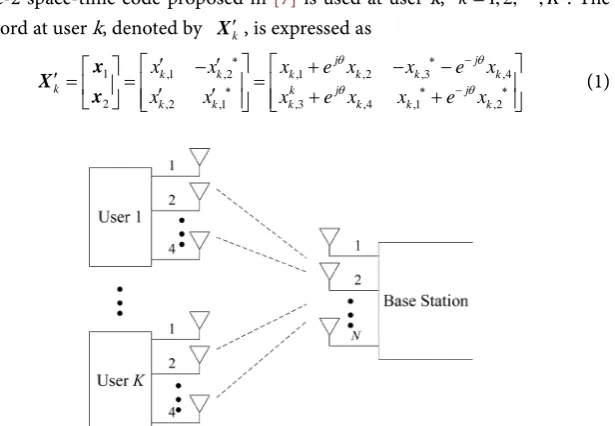
New transmission scheme based on space-time code is proposed for massive MIMO system, which consists of K users and a base station. Each user is equipped with four antennas and two of them are selected to send space-time codeword with Alamouti coded by using the method of generalized spatial modulation. The base station estimates the index of transmit antennas used by each user at first, and then uses an iterative method to separate each space- time codeword and decode modulated signals of each code-word. Compared with the existing scheme for the same scene, the proposed scheme reduces the complexity of decoding, while keeping the same transmission rate. Simulation results demonstrate that the proposed scheme outperforms the existing scheme in the same scene when the base station is equipped with large amount of antennas.
Subject Areas
Information and Communication Theory and Algorithms
Keywords
Massive MIMO Systems, Space-Time Code, Decoding Complexity, Generalized Spatial Modulation
1. Introduction
Transmission rate and spectrum efficiency are particularly important for multi- cell communication. Massive MIMO technology have the ability to improve spectrum efficiency, cut down transmission power, reduce intra cell interference and inter-cell interference of the system without increasing spectrum resources [1]. So, it becomes one of the breakthrough technologies in the future [2].
In massive MIMO system, the base station is equipped with hundreds of an-tennas. K users transmit modulated signals simultaneously, or transmit the sig-How to cite this paper: Tian, X.J., Jia, W.J.
and Zhang, H.T. (2017) New Transmission Scheme Based on Space-Time Code for Massive MIMO. Open Access Library Jour- nal, 4: e3712.
https://doi.org/10.4236/oalib.1103712
Received: June 6, 2017 Accepted: June 26, 2017 Published: June 29, 2017
Copyright © 2017 by authors and Open Access Library Inc.
This work is licensed under the Creative Commons Attribution International License (CC BY 4.0).
http://creativecommons.org/licenses/by/4.0/
nals after precoding at the same time in a single cell uplink system [3]. If all of the users are equipped with nt antennas, there will be nt modulation sym-bols sent by each user per time slot [4][5]. Generalized spatial modulation is studied in [6], in which not only transmit antennas send symbols, but also dif-ferent antenna combinations are mapped into several bits. Thus, the transmis-sion efficiency is improved. However, the decoding complexity of Maximum Li-kelihood (ML) decoding, Message Passing (MP) decoding and Channel Har-dening Exploiting Message Passing (CHEMP) in [6] is too high.
In order to reduce the decoding complexity, the transmission based on space- time coding is proposed in single-cell massive MIMO uplink system. All of the users are equipped with 4 antennas and generalized spatial modulation is used at each user. According to the information sequence, two of the antennas are se-lected to transmit the space-time code which has Alamouti structure. Firstly, the serial number of the transmit antenna used at each user are estimated at the base station. Then, each space-time codeword is separated using the orthogonality of Alamouti code. Finally, modulation symbols in each codeword are detected. The ML decoding complexity of the proposed scheme is proportional to the square of the modulation order. The simulation results show that the reliability of the pro-posed scheme is better than [6].
2. System Model
The system model of the proposed scheme is shown in Figure 1, which contains
K users and a base station. All users are equipped with 4 antennas and the base station is equipped with N N
(
≥4K)
antennas. Generalized spatial modulation proposed in [6] is adopted. Each user selects two antennas to transmit signals according to the information sequence. When the information sequences are 00, 01, 10 and 11, the corresponding antenna combinations are (1, 2), (1, 3), (1, 4) and (2, 3), respectively.Rate-2 space-time code proposed in [7] is used at user k, k=1, 2,,K. The codeword at user k, denoted by Xk′, is expressed as
1 ,1 ,2 ,1 ,2 ,3 ,4
2 ,2 ,1 ,3 ,4 ,1 ,2
j j
k k k k k k
k k j j
k k k k k k
x x x e x x e x
x x x e x x e x
θ θ
θ θ
∗ ∗ −
∗ ∗ − ∗
′ − ′ + − −
′ = = ′ ′ = + +
x X
[image:2.595.233.541.503.716.2]x (1)
where, xk,λ represents the modulation symbols, λ=1, 2, 3, 4, j= −1,
( )
*
⋅
represents conjugate. The value of θ makes the elements of Xk′ nonzero. Assume that
(
µ ν
k, k)
are the antenna numbers selected by user k,{
1, 2, 3, 4}
k k
µ ν
≠ ∈ , µ νk < k. Then the antenna µk at user k sends x1, the antenna νk sends x2 and the other antennas send[
0 0]
. Use Xk to represent the codeword send by user k. The dimension of Xk is4 2
×
. The elements of Xk in the row of µk and νk are x1 and x2 respectively, and the elements in other rows are zero.The received signals at the base station, denoted by
Y
, can be expressed as1 1 2 2
1 1 2 2
1,1 1,4 1,1 1,4 1,1 1,4 1,1 1,2 1,1 1,2
1 1 2 2
,1 ,4 ,1 ,4 ,1 ,4 ,1 ,2 ,1 ,2
K K
K K
K K
N N N N N N K K N N
h h h h h h n n
h h h h h h n n
= + + + +
= +
N H
Y H X H X H X N
x x
x x
(2)
where, dimension of
Y
andN
are both N×2.N
represents the complex Gauss noise matrix with zero mean and variance of σ2.k
H , with dimension
4
N× , represents the channel fading coefficient from user k to the base station.
The dimension of xk,1 and xk,2 are both
4 1
×
. The µk-th and νk-th ele-ments of xk,1 are xk′,1 and xk′,2, respectively. The µk-th element and νk-th element of xk,2 are xk′,1 and xk′,2, respectively. The other elements of xk,1 and xk,2 are zeros.3. Detection
The detection at the base station can be divided into two steps. Firstly, the serial number of the transmit antennas at each user is estimated at the base station ac-cording to the received signals and the channel state information (CSI). Then, each codeword is separated and each element of the codeword is estimated using iterative method at the base station.
Use y1′ to represent the first column of
Y
. Let g=pinv( )
H y1′, which( )
pinv ⋅ represents pseudo inverse. g is a vector with a dimension of
4
K
×
1
. Use gk to represent the vector with a dimension of4 1
×
, which consists of the(
)
4 k− +1 1-th element to 4k-th emelent of g, k=1, 2,,K. According to the estimation method of transmitting antennas’ number in (2) and [8], the serial number of the transmit antennas for user k obtained at the base station can be
expressed as
(
)
(
)
,
0, 0 arg max k k k
k k k k
k k g g
g g
µ ν µ ν
µ ν
µ ν
′ ′∈ ′ ′
′≠′
= +
g (3)
where,
µ
k0≠ν
k0∈{
1, 2, 3, 4}
, gµ′k and gν′k represents the µ′-th and ν′-thelement of gk. ⋅ represents norm.
After the serial number of transmit antenna is estimated, the zero elements in (2) can be removed. Then, (2) can be equivalently expressed as
1′ ′1 2′ ′2 K′ ′K
= + + + +
where, Xk′ represents a
2 2
×
matrix after removing the zero elements in Xk, which is expressed as (1), k=1, 2,,K . Hk′ represents a N×2 matrix,which consists of µk-th column and νk-th column of Hk. Since Xk′ has Alamouti structure, (4) can be expressed as
1 1 2 1
1 1 1 1
2 2
1 2
K
K
N N N K
N N = + y n
H H H s
y n
H H H s
y n
(5)
where ,1 ,2
,2 ,1
k k
i i
k
i k k
i i
h h
h ∗ h ∗
=
−
H ,, i ni,1 ni,2 T
∗
=
n , yi j, represents the element of
Y
in row i and column j,, j=1, 2.( )
⋅T represents the transpose.According to the method of separating Alamouti codewords in [9] and [10], (5) can be decomposed into Λ = N K sub-equations, which ⋅ represents round down operation. Each sub-equation can be expressed as
( ) ( ) ( ) ( )
1 1
1
1 2
1 1 1 1 1 1
1 2
1 2
1 1 1 1 1 1 1 1
1 2
K
K
K K K K K K
K
K K K K
K
K K K K
Λ Λ
Λ− + Λ− + Λ− + Λ− +
Λ Λ Λ Λ
= + = y n H y H
y H H H s n
y H H H s n
y H H H
y H H H
( 1) 1
1 K K K Λ Λ− + Λ + n n s s n (6) Let
( )
( )
(
)
(
)
(
)
( ){
}
{
}
,, 2 ,
1 1
, , 1
2 2 1 , 1 1 1 , 1
1, , 1 , 1, , |
H j
H H
j j
K l K l H
j K l
K l K l l l l l l l
l K j K l l
− + − + − + − + − + = − − = − − ∈ − ∈ − F
G I F
H H
I
H
(7)
where,
( )
H⋅ represents conjugate transpose, I2 represents a unit matrix with a dimension of
2 2
×
. From (4)-(8) in [10], codewords can be separated gradually by(
K−1)
times iteration. The matrix, vector and element with subscript
belong to the
-th sub-equation after decomposition, =1,,Λ.From (25) in [10], we can find that, the
-th sub-formula from (6) can be expressed as (8) after(
K−1)
times iterative,( )
1
1 1
1 ,1 ,2 1
1
ˆ ˆ ˆ ˆ ˆ
K
H H H H H
K − + = + = +
H
H
G y G s G n G h h s G n
H
where,
(
)
(
)
( )( )
(
)
( )( )
( )
2 ,1 ,1 ,2 1,1 ,2 ,1
,3
1
, , ,1
1 1 2 1 ˆ K K l K l l K K K l ϕ ϕ − − = − − + − = =
∑
I A F AF A F
A G
A A F
, ( )
( )
, n kϕ A
represents a function replace all of F,ψ
( )
l in A,k to F,ψ +n(
l−n)
,{
1, , 1}
n∈ K− ,
ψ
∈{
1,,K−1}
. ( )( )
2 2 nϕ I =I , A,k is a matrix with di-mension
2 2
×
, h,1 and h,2 represent the 1-th column and 2-th column of( )
(
1 1 1)
(
( )1 1 2)
( )
1H
H H H
K
K K
− + − +
H H H respectively.
Let ˆ ,1 ,2
H
H = G h h , and multiply both sides of (8) by HH to get 1
ˆ ˆ
H H = H + H H
H G y H H s H G n
(9) Since the matrix with Alamouti structure is closed for addition, multiplication, and conjugate transpose operations, H has Alamouti structure, which result in =
(
1,1 ˆ ˆ1 1 1,1 ,1 ˆ ˆ ,1)
2H H H H H
Λ Λ Λ Λ
+ +
H H h G G h h G G h I . Use r1 to represent the first element of H ˆ H
H G y, then (10) can be obtained by (6)-(9).
(
)
(
)
1 1,1 1 1 1,1 ,1 ,1 1,1
1,1 1 1 1 ,1
ˆ ˆ ˆ ˆ ˆ ˆ ˆ ˆ
H H H H
H H H H
r Λ Λ Λ Λ x
Λ Λ Λ Λ
′
= + +
+ + +
h G G h h G G h
h G G n h G G n
(10)
The base station can get x1,1′ from r1 directly. The detection of the other modulation symbols is similar. Since Xk′ has Alamouti structure and each co-deword consists of two modulation symbols, the complexity of ML decoding is proportional to the square of the modulation order.
4. Bit Error Rate Analysis
Let Pe1 and Pe2 represents the error probability of estimating the number of transmit antennas and the symbol error rate (SER) of the second step. Then the SER of the system can be expressed as
(
1)(
2)
1 1 1
e e e
P = − −P −P (11) We deduce Pe2 firstly. Assume the mathematical expectation of the modula-tion signal is P1. The signal-noise ratio (SNR) during the process of decoding
1,1
x′ , denoted by ρ, can be obtained from (10).
(
)
2(
)
21,1 1 1 1,1 ,1 ,1
1 2
1,1 1 1 1 1 1,1 ,1 ,1
ˆ ˆ ˆ ˆ
ˆ ˆ ˆ ˆ ˆ ˆ ˆ ˆ
H H H H
H H H H H H
P
ρ
σ
Λ Λ Λ Λ
Λ Λ Λ Λ Λ Λ
+ + =
+ +
h G G h h G G h
h G G G G h h G G G G h
(12)
According to the estimation method of SER in [10] and [11], the probability of estimating x1,1′ as xˆ1,1′ , denoted by Pe2, can be expressed as
(
)
1,1 1,122 1,1 1,1
1
2 2
2
1,1 1,1 1,1 1,1 2
2 1,1 1,1 1,1 1,1
ˆ ˆ
2
ˆ ˆ
1 1 1 1
ˆ ˆ
exp
2 4 2 4 2 4
e
x x
P P x x Q
x x x x
x x x x
where,
( )
⋅ represents mathematical expectation. The value of x1,1′ −xˆ1,1′ de-pends on the modulation mode.In what follows, we derive Pe1. According to the consistent bound method proposed by (12) in [12] and [13], Pe1 satisfies the following equation
( )
(
)
( )
(
)
1 0 0
ˆ
4 4 0 0
ˆ
1 1 1
ˆ ˆ , ˆ ˆ , 4 e M q
P N P
N P M ξ ξ ξ ξ ξ ξ ξ = = = ≤ → → ≤
∑
∑∑∑
x x x x (14)where, M represents the modulation order, ξ represents the serial number of transmit antennas,
ξ
ˆ is the number of antennas estimated by the base station.0
x is the first column of X1. xˆ0 is the decoding results obtained by decoding the first column of X1. N
( )
ξ ξ
,ˆ represents the number of error bits betweenξ and
ξ
ˆ.It is known from (18) in [12] and (5) in [14],
(
)
( )
1(
( )
)
0 0 0 1 ˆ 1 N N N
P f f β
β β α α β − = − + → = −
∑
x x (15)
where,
( )
1 12 1
f α α
α = − + , 4 2 2 1 1
4 ξ xξ xξ
α
σ =
=
∑
− , xξ represent theξ
-thelement of x0,
ξ
∈{
1, 2,3, 4}
. Substitute (15) into (14) to get( )
( )
1(
( )
)
4 4
0 1
ˆ 1 1 1
1 ˆ , 1 4 N N M e q N
N f f
P M β β ξ ξ β
ξ ξ α α
β − = = = = − + −
≤
∑∑∑
∑
(16)Take (13) and (16) into (11) to get the SER of the system, as shown in (17).
( )
( )
(
( )
)
(
)
1 4 4 0 2 1,1 1,1 ˆ1 1 1
1 ˆ
, 1
ˆ
1 1 1
4 N N M e q N
N f f
P x x
M
β
β
ξ ξ
β
ξ ξ α α
β ρ − = − = = = − + − ′ ′ ≤ − − − −
∑
∑∑∑
(17)5. Simulation Results and Analysis
This chapter simulates the reliability of the proposed scheme and the reliability of [6]. Assume the channel follows the Rayleigh distribution and the noise is Gaussian white noise. There are 16 users using 4QAM modulation without channel coding.
The error probability Pe1 of estimating the transmit antenna number when the base station is equipped with 64 antennas is shown is Figure 2. Simulation results show that when the SNR is 22dB, the error probability is about 3
Therefore, the error probability of the estimate of transmit antenna number is not plot in Figure 2 when N = 128.
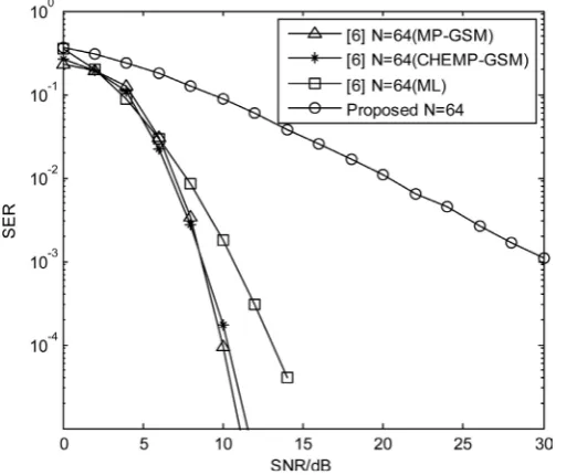
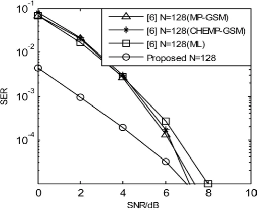
The SER curves of the proposed scheme and the scheme in [6] with 64 anten-nas and 128 antenanten-nas is shown in Figure 3 and Figure 4 respectively. Simulation results show that when N = 64, the reliability of the proposed scheme is lower than [6],when N = 128, the reliability of the proposed scheme is better than [6]. That is because when N = 64 the Pe1 of the proposed scheme is higher, but when N = 128 the Pe1 of the proposed scheme is zero. From Figure 4, the gain of the proposed scheme is about 2.5 dB at the SER of 3
[image:7.595.246.500.247.475.2]10− compared with the MP-GSM scheme, the gain is about 2.7 dB compared with the CHEMP-GSM scheme, and the gain is about 2.9 dB compared with the ML scheme.
Figure 2. The error probability of estimating the transmit antenna with N = 64.
[image:7.595.248.514.505.720.2]Figure 4. SER curves with N = 128.
6. Conclusion
Compared with the existing scheme, each user adopts rate-2 space-time code. The transmission efficiency is the same as the existing scheme. The proposed scheme uses the orthogonal characteristics of the equivalent channel matrix cor-responding to the Alamouti codeword to gradually separate each codeword, and then decodes each symbol of the codewords. The decoding complexity is greatly reduced. However, the reliability of the proposed scheme is greatly dependent on the estimated of the transmission antenna. How to reduce the dependency of the reliability of the system on the estimated transmit antenna number requires fur-ther study.
References
[1] Ye, Q., Bursalioglu, O.Y., Papadopoulos, H.C., et al. (2015) User Association and Interference Management in Massive MIMO HetNets. arXiv preprint ar-Xiv:1509.07594,.
[2] Larsson, E., Edfors, O., Tufvesson, F., et al. (2014) Massive MIMO for Next Genera-tion Wireless Systems. Communications Magazine, IEEE, 52, 186-195.
https://doi.org/10.1109/MCOM.2014.6736761
[3] Zia, M.S. and Hassan, S.A. (2015) Outage Analysis of Multi-User Massive MIMO Systems Subject to Composite Fading. Vehicular Technology Conference (VTC Spring), 2015 IEEE 81st. IEEE, 1-5.
[4] Hassan, S.A. (2015) On Achievable Rates in Massive MIMO-Based Hexagonal Cel-lular System with Pilot Contamination. Vehicular Technology Conference (VTC Spring), 2015 IEEE 81st. IEEE, 1-5.
[5] Narasimhan, T.L. and Chockalingam, A. (2014) CHEMP Receiver for Large-Scale Multiuser MIMO Systems Using Spatial Modulation. Signal Processing Conference
(EUSIPCO), 2014 Proceedings of the 22nd European. IEEE, 86-90.
Wireless Communications, 14, 3764-3779.
https://doi.org/10.1109/TWC.2015.2411651
[7] Tian, X.J. and Li, X.J. (2015) Improved Interference Cancellation Method over Y Channel. Journal of University of Science and Technology of China, 11, 943-948. [8] Mesleh, R., Haas, H., Ahn, C.W., et al. (2006) Spatial Modulation—A New Low
Complexity Spectral Efficiency Enhancing Technique. ChinaCom’06. First Interna-tional Conference on Communications and Networking in China, 1-5.
[9] Kim, J., No, J. and Shin, D. (2014) Two-Way Relaying Schemes with Alamouti Code. 2014 International Conference on Information and Communication Tech-nology Convergence (ICTC), 638-639.
[10] Kim, J., Jin, D.S., Jin, X., et al. (2015) Interference Alignment-and-Cancellation Scheme Based on Alamouti Code for the Three-User Multi-Input–Multi-Output Interference Channel. IET Communications, 9, 1278-1288.
https://doi.org/10.1049/iet-com.2014.1084
[11] Bhatnagar, M.R. and Hjørungnes, A. (2010) Improved Interference Cancellation Scheme for Two-User Detection of Alamouti Code. IEEE Transactions on Signal Processing, 58, 4459-4465. https://doi.org/10.1109/TSP.2010.2048211
[12] Naidoo, N.R., Xu, H.J. and Quazi, T.A.M. (2011) Spatial Modulation: Optimal De-tector Asymptotic Performance and Multiple-Stage Detection. IET Communica-tions, 5, 1368-1376. https://doi.org/10.1049/iet-com.2010.0667
[13] Proakis, J.G. (2009) Digital Communications. 5th Edition, McGraw-Hill, Singapore. [14] Serafimovski, N., Sinanovic, S., Younis, A., et al. (2011) 2-User Multiple Access
Spa-tial Modulation. IEEE GLOBECOM Workshops (GC Wkshps), 343-347.
Submit or recommend next manuscript to OALib Journal and we will pro-vide best service for you:
Publication frequency: Monthly
9 subject areas of science, technology and medicine
Fair and rigorous peer-review system Fast publication process
Article promotion in various social networking sites (LinkedIn, Facebook, Twitter,
etc.)
Maximum dissemination of your research work
Submit Your Paper Online: Click Here to Submit